Table of Contents
Advertisement
Advertisement
Table of Contents
Troubleshooting

Summary of Contents for Harmonic ELECTRA VS
- Page 1 LECTRA Convergent Video System Version 05.10 User Manual Rev. A...
- Page 2 Copyright © 2017 Harmonic Inc. All rights reserved..
-
Page 3: Table Of Contents
Mounting the Front Panel on 6RU Device....... 46 Powering Up ................50 6RU and 10RU Device Specifics ........... 50 Performing the Initial Settings ..........50 Preparing the Connection ............. 50 Electra VS - Version 05.10 User Manual - Rev. A... - Page 4 Configuring the Interface of the First Node (Master Node) 61 Accessing the Web Interface for the First Time ....63 Adding the Second Masterisable Node in Electra VS ..65 Asking a License for Electra VS ..........67 Declaring a License for Electra VS ........67 Adding Non Masterisable Node(s) to Electra VS ....
- Page 5 Setup/IP ................168 Network interface profiles ..........168 LANs................. 169 Routes ................170 DNS .................. 171 System Private LAN ............171 IGMP ................172 Setup/Network Storage............173 Setup/Hot Folder..............173 Electra VS - Version 05.10 User Manual - Rev. A...
- Page 6 Logs Array................208 Filters and Sorting Options..........208 Advanced ................210 Statmux Tab ................211 Statmux Editing ..............212 Simulation Tab ................. 213 Purpose ................213 Operating Instructions ............213 Electra VS - Version 05.10 User Manual - Rev. A...
- Page 7 PS Video Extractor ............267 PS Audio Extractor............268 YUV File Input..............269 Decoding ................270 Audio Decoder..............270 Dolby® E Decoder............270 Video Decoder ..............272 Preprocessing ..............275 Electra VS - Version 05.10 User Manual - Rev. A...
- Page 8 Layout of the IPTV TSoIP input Sample Workflow ... 388 Layout of the Mosaic - 6 HD Inputs Sample Workflow..389 Layout of the WebTV - HLS WebDAV Sample Workflow. 390 Electra VS - Version 05.10 User Manual - Rev. A...
- Page 9 For 1RU Devices: Accessing the BIOS......421 Requesting a New License File........... 427 Declaring a New License File..........427 Adding a 1RU Diskless Node to Electra VS ....... 427 Replacing a Hot Swappable Part..........429 Electra VS - Version 05.10...
- Page 10 Frequently Asked Questions ..........453 Why cannot I instantiate my job whereas there is space on the Electra VS? ......453 I do not see my workflow in the list when I want to create a job. Why?.......... 453 I cannot create a workflow.
- Page 11 IP Address of the Device..........475 Performing the IP Configuration from the HP Interface..477 Accessing the Interconnect Bays’ Management Console 477 Configuring the Interconnect Bays........479 Saving your Configuration..........479 More Information..............480 Electra VS - Version 05.10 User Manual - Rev. A...
- Page 12 Electra VS 10RU..............482 Electra VS 10RU (AC 200-240V single phase)....482 Electra VS 10RU (AC NA Triple Phase @ 208VAC) ..486 Electra VS 10RU (AC INTL Triple Phase @ 230VAC)..490 Electra VS 10RU (AC JPN Triple Phase @ 200VAC)..494 Electra VS 10RU (DC 48V) ..........
- Page 13 How to Use a Configuration File........576 Description of Configuration Files ......... 577 Multicast Management ............579 Heterogeneous System Configuration ........579 Interface Bitrates ..............580 Bitrate Allocation on 10RU Interfaces ........ 580 Electra VS - Version 05.10 User Manual - Rev. A...
- Page 14 588 Conversions according to default strategies and output display aspect ratio ................590 Specific output AFD according to source or output display aspect ratio ..................591 Glossary ............593 Electra VS - Version 05.10 User Manual - Rev. A...
-
Page 15: Preface
The Electra VS User Manual contains background information about the Electra VS Convergent Video System, and describes operating procedures. This manual can be used while learning about Electra VS, and for enhancing your basic knowledge of the product. The Electra VS Quick Start Guide contains information about installing and configuring the equipment. - Page 16 SNMP community string and the access rights. You will also find MIB description, how to register the SNMP Manager on the Electra VS Graphical User Interface etc. It also describes the MIB used to configure and monitor the equipment.
- Page 17 Preface — About this Manual Appendix G ’ESAM’ provides information on how Electra VS is implementing the API Signal Confirmation and Conditioning for CableLabs® ESAM (Event Signaling and Management). Appendix H ’Aspect Ratio Conversions’ provides the default conversion performed and the AFD value set according to the input AFD and aspect ratio.
- Page 18 Notes provide supplementary information. They are highlighted for emphasis, as in this example, and are placed immediately after the relevant text. Electra VS - Version 05.01 User Manual - Rev. A...
- Page 19 Example: “The MIB is at the following location: C:\MIB” . Important Notice Harmonic reserves the right to make corrections, modifications, enhancements, improvements and other changes to its products or services at any time and to discontinue any product or service without notice.
- Page 20 Dolby Laboratories. MPEG-2 / MPEG-4 AAC audio encoding technology is authorized Fraunhofer license (http://www.iis.fraunhofer.de/amm/). All other tradenames referenced are service marks, trademarks, or registered trademarks of their respective companies. Electra VS - Version 05.01 User Manual - Rev. A...
-
Page 21: Chapter 1 Overview
Chapter 1 Overview Introduction This chapter gives a general description of the Electra VS and its main features. In this Chapter ’Purpose’ ..................page 22 ’Main Features’ ................page 24 ’Hardware Delivery’ ..............page 25 ’Software Only Delivery’ ............page 29 ’Virtualization Delivery’ ..............page 30 Electra VS - Version 05.10... -
Page 22: Purpose
The Electra VS can be delivered in different ways: Hardware delivery: In this way the Electra VS software is delivered installed on an HP server (1RU/6RU/10RU platform) Software only delivery: In this way the Electra VS software is delivered with Operating System must installed HP/Dell/Cisco/Fujitsu server not provided. - Page 23 Chapter 1 ’Overview’ — Purpose Figure 1-1. Electra VS applications Electra VS 1RU Electra VS 10RU Electra VS - Version 05.10 User Manual - Rev. A...
-
Page 24: Main Features
1RU HP server. Interface with Placement Opportunity Information System (POIS) compliant with CableLabs® ESAM (Event Signaling Management) for ad-insertion. Black out management and slate insertion on WebTV applications. Electra VS - Version 05.10 User Manual - Rev. A... -
Page 25: Hardware Delivery
Hardware Delivery Chassis Overview The hardware delivery of the Electra VS product is proposed on two HP chassis: 1RUx19” or 10RUx19” . The Electra VS software can also be deployed on hardware used by VS7000 product but no more available with Electra VS. ... -
Page 26: Rear Panel
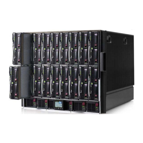
Figure 1-3. Electra VS 6RU server front panel 10RU Front Panel Figure 1-4. Electra VS 10RU server front panel Rear Panel 1RU Rear Panel Figure 1-5. Electra VS G7 1RU server rear panel slot 1 slot 2 slot 0 Electra VS - Version 05.10... - Page 27 Chapter 1 ’Overview’ — Hardware Delivery Figure 1-6. Electra VS G8 1RU server rear panel slot 2 slot 1 slot 0 Figure 1-7. Electra VS G9 1RU server rear panel slot 1 slot 2 slot 0 6RU Rear Panel Figure 1-8. Electra VS 6RU server rear panel Electra VS - Version 05.10...
- Page 28 Chapter 1 ’Overview’ — Hardware Delivery 10RU Rear Panel Figure 1-9. Electra VS 10RU server rear panel Electra VS - Version 05.10 User Manual - Rev. A...
-
Page 29: Software Only Delivery
Electra VS is a software-based solution leveraging Harmonic’s dedicated Video Operating System: VOS Flex. It operates on off-the-shelf IT servers. For operators owning their servers, Electra VS is available as Electra VS Software Edition. More informations on requirements and examples of platforms are available in Appendix A ’Technical... -
Page 30: Virtualization Delivery
Video Operating System: VOS Flex. It operates on off-the-shelf IT servers. For operators owning virtualization infrastructure, Electra VS is available as Electra VS Virtualized Edition. Virtualization Technologies Electra VS Virtualized edition can be delivered as a virtual machine. Today, it supports the following virtualization technology: - VMWare technology More... -
Page 31: Installation And Startup
Introduction This chapter provides the procedures required for Electra VS installation and initial configuration in the different cases of delivery. It also contains a list of HP documents to which you can refer for more information on the blade centers. -
Page 32: Hardware Delivery
Chapter 2 ’Installation and Startup’ — Hardware Delivery Hardware Delivery Chassis Overview The hardware delivery of the Electra VS product is proposed on three HP chassis: 1RUx19” , 6RUx19” , or 10RUx19” . Physical characteristics are as follows: Hot swappable power supplies ... -
Page 33: Front Panel
Chapter 2 ’Installation and Startup’ — Hardware Delivery Front Panel Figure 2-1. Electra VS 10RU server front panel Figure 2-2. Electra VS 6RU server front panel Figure 2-3. Electra VS 1RU server front panel Electra VS - Version 05.10 User Manual - Rev. A... - Page 34 The 1RU front panel is equipped with a Slide-out System Insight Display (SID) panel which shows the equipment status. Figure 2-4. Slide-out System Insight Display on the Electra VS 1RU server front panel This SID features LEDs that help you to diagnose a server failure.
-
Page 35: Rear Panel
Chapter 2 ’Installation and Startup’ — Hardware Delivery Rear Panel Figure 2-5. Electra VS 10RU server rear panel Figure 2-6. Electra VS 6RU server rear panel Figure 2-7. Electra VS G7 1RU server rear panel slot 1 slot 2 slot 0 Electra VS - Version 05.10... - Page 36 Chapter 2 ’Installation and Startup’ — Hardware Delivery Figure 2-8. Electra VS G8 1RU server rear panel slot 2 slot 1 slot 0 Figure 2-9. Electra VS G9 1RU server rear panel slot 1 slot 2 slot 0 Depending on the server, the content of the slots may vary: ...
- Page 37 Depends on IN1 IN2 IN3 IN4 board model Optional additional network SD SDI octo board: SD SDI octo board: IN13 IN14 IN15 IN16 connectors (8 to 5) IN10 IN11 IN12 Electra VS - Version 05.10 User Manual - Rev. A...
-
Page 38: Hp Documentation
HP provides a number of documents for their blade centers. These documents are available on the HP Web site, but you can also find them on the DVD-ROM delivered with the Electra VS: HP BladeSystem c7000 Enclosure - Setup and Installation Guide ... - Page 39 HP Proliant DL360 G7 Quick Specs HP Proliant BL460c G8 Quick Specs HP Proliant DL360p G8 Quick Specs HP Proliant DL360 G9 Quick Specs HP Proliant DL460c G9 Quick Specs Electra VS - Version 05.10 User Manual - Rev. A...
-
Page 40: Unpacking
Front panel DVD-ROM Mounting in Rack (Recommendations) Rack mounting is not mandatory for Electra VS but the ventilation and safety requirements given in this section must be observed in all cases. Ventilation Please refer to the recommendations provided by HP . -
Page 41: Power Supply And Protective Ground
If in doubt, contact a qualified electrician. Electra VS End Plug the power cord(s) into the mains inlet. Electra VS - Version 05.10 User Manual - Rev. A... -
Page 42: Installing The Device (Steps)
Figure 2-13. Mounting the front panel – Engaging the right side of the front panel Press the left side of the front panel to fix it. Figure 2-14. Mounting the front panel – Press the left side on the front panel Electra VS - Version 05.10 User Manual - Rev. A... -
Page 43: 10Ru And 6Ru Devices
To install the front panel, the left or right hinge must be removed depending on whether left- or right-opening is required. This operation is explained below. Procedure to Install a Left-Opening Front Panel (Hinges on Left) Figure 2-15. Front panel with left-opening Electra VS - Version 05.10 User Manual - Rev. A... - Page 44 Figure 2-18. Inserting the front panel into the bottom left hinge Electra VS - Version 05.10 User Manual - Rev. A...
- Page 45 Procedure to Install a Right-Opening Front Panel (Hinges on Right) Figure 2-20. Front panel with right-opening Remove the top right hinge as shown in Figure 2-23 (this time with the right hinge). Electra VS - Version 05.10 User Manual - Rev. A...
-
Page 46: Mounting The Front Panel On 6Ru Device
2 screws at the top and bottom of the left hinge To install the front panel, the left or right hinge must be removed depending on whether left- or right-opening is required. This operation is explained below. Electra VS - Version 05.10 User Manual - Rev. A... - Page 47 Position the left hinge so that the top screw inserts into the hole in the top part of the front panel. Figure 2-24. Inserting the left hinge in the top part of the front panel (top) Electra VS - Version 05.10 User Manual - Rev. A...
- Page 48 Procedure to Install a Right-Opening Front Panel (Hinges on Right) Figure 2-27. Front panel with right-opening Remove the right hinge as shown in Figure 2-23 (this time with the right hinge). Electra VS - Version 05.10 User Manual - Rev. A...
- Page 49 Figure 2-25 (this time with the right hinge). Re-mount the right hinge and front panel together on the chassis as shown in Figure 2-26 (this time with the right hinge). Electra VS - Version 05.10 User Manual - Rev. A...
-
Page 50: Powering Up
Chapter 2 ’Installation and Startup’ — Hardware Delivery Powering Up Check that Electra VS is not yet connected to a LAN. Factory-set IP addresses may cause disturbance (address conflict) on the LAN when Electra VS is switched on. Connect the power cord(s). -
Page 51: Accessing The Web Interface For The First Time
IGMP Querier. The switch must act as such. The IP source of the IGMP querier shall exist in the system private LAN. If the Electra VS includes at least one 10RU HP blade center and others hardware platforms, to ensure a proper multicast management in the System Private LAN, it must contain an IGMP Querier. -
Page 52: Performing The Ip Configuration
Once you have made the IP configuration from the GUI: Disconnect the supervision PC from the GigE switch. Depending on the composition of the Electra VS: If the Electra VS contains several 10RU blade centers or a mix of 1RU and 10RU devices: Electra VS - Version 05.10... -
Page 53: Establishing The Definitive Connection
Web browser. Type in the address bar the supervision IP address that you configured earlier and press Enter. Use the following account information: Login: admin Password: admin Electra VS - Version 05.10 User Manual - Rev. A... -
Page 54: Setting The Date And Time
Saving Time. Figure 2-29. Date and time settings Click Apply. Selecting the Supervision Protocol If you want to secure the protocol used to communicate with the Electra Select the Setup tab. Electra VS - Version 05.10 User Manual - Rev. A... - Page 55 processing component. Our Electra VS in HTTPS is secured by a certificate, therefore the explorer will warn you that the security certificate was issued for a different website's address. You can check that it is effectively issued for www.harmonicinc.com.
-
Page 56: Starting The Operation
Chapter 2 ’Installation and Startup’ — Hardware Delivery Starting the Operation Refer to Chapter ’Web User Graphical Interface’, section ’Operating Instructions (Tutorial)’ on page 87. Electra VS - Version 05.10 User Manual - Rev. A... -
Page 57: Software Only Delivery
Prepare your network environment and the network addressing plan. Preparing the System Private LAN The first physical interfaces of the Electra VS platforms will be connected to a single GigE switch. The GigE switch shall be use for the Electra VS System Private LAN: ... -
Page 58: Creating The Bootable Usb Flash Drive
Write the image on the USB Flash drive. Preparing the Hardware Platform Select the node that will be one of the two masters of the Electra VS. If you have two disks Install hardware RAID 1 if you want to use a hardware RAID. ... - Page 59 Chapter 2 ’Installation and Startup’ — Software Only Delivery Plug the USB Flash drive in the master server. Power up the server. Select Install Electra VS on local host: RUN VS7000 (for evaluation using NodeBench tool) Install VS7000 on Local host Partition disks Selection of the partitioning method.
- Page 60 Chapter 2 ’Installation and Startup’ — Software Only Delivery Finish the partitioning - Select Finish partitioning and write changes to disk. - Press Enter. Select Yes and press Enter. The installation of the Electra VS starts. Electra VS - Version 05.10 User Manual - Rev. A...
-
Page 61: Configuring The Interface Of The First Node (Master Node)
The management address will be set to 198.18.69.244 in LAN 3064. ifConfig: display the configuration of the interfaces present in the node. Eth0 is preconfigured and eth1 is in our exemple configured to support the management network. Electra VS - Version 05.10 User Manual - Rev. A... - Page 62 Connect the management interface (eth1 / INTF_2) of the master node to a remote PC or the management system. You can now connect to the Electra VS Web interface using the remote PC.. If you reboot the master node before importing the license file, the network configuration will be lost.
-
Page 63: Accessing The Web Interface For The First Time
and check the interface configuration typing IfConfig command (see step Configure the interface of the master node). Connect to the Electra VS Use the following account information: Login: admin Electra VS - Version 05.10 User Manual - Rev. A... - Page 64 Read and accept the End User License Agreement (EULA). The End User License Agreement shall be accepted only the first time the Web interface is opened or after an upgrade if the agreement condition have been updated. Electra VS - Version 05.10 User Manual - Rev. A...
-
Page 65: Adding The Second Masterisable Node In Electra Vs
(check its status in the bottom-right corner of the windows). Adding the Second Masterisable Node in Electra VS Install the version from the USB Flash drive on a second node with disk (Refer to steep 1 to 6 in the section ’Installing the Version on the... - Page 66 Select it and click Next. A Network interface profile compatible with the hardware is automatically associated with the node. Check if the number of physical interfaces detected is correct. Electra VS - Version 05.10 User Manual - Rev. A...
-
Page 67: Asking A License For Electra Vs
The second node is added to the Electra VS: Asking a License for Electra VS Ask a license file for the Electra VS in order to declare the two masterisable nodes. The license file shall contain all the licenses you purchased. -
Page 68: Adding Non Masterisable Node(S) To Electra Vs
Refer to section ’Setup/IP’ on page 168. Adding Non Masterisable Node(s) to Electra VS Refer to Chapter 4 ’Servicing’, section ’Adding Non Masterisable Node(s) to Electra VS’... -
Page 69: Virtualization Delivery
Virtualization Delivery Hardware Recommendation For operators already owning their VMware virtualization infrastructure, Electra VS is available as Electra VS Virtualized Edition. It is delivered as a virtual machine (loadable in ESXi). More information on requirements and examples of platforms are available in the Electra VS-Checklist documentation delivered in the DVD-ROM with the product. - Page 70 Electra VS Management LAN) will be eth1 at Electra VS OS layer, and NIC2 in Electra VS GUI. During the deployment of the Electra VS VM, the networks of the VM will be associated to the ones configured in the ESXi, so use explicit names such as: VM Network CC, VM Network System Private, VM Network Data In, VM Network Data Out, VM Network Internal Data.
- Page 71 Chapter 2 ’Installation and Startup’ — Virtualization Delivery System private VMPG is mandatory, even if you have only one node. But in this case, there is no need to associate this VMPG to a physical interface. Electra VS - Version 05.10 User Manual - Rev. A...
-
Page 72: Installing The Ova On The First Node (Master Node)
VM and the ones of the ESXi. When the deployment is finished check the configuration as follows: Right-click the virtual machine name (for example Electra VS_1) > Edit Settings..Electra VS - Version 05.10 User Manual - Rev. A... - Page 73 Configure the Number of cores per socket to correspond to the real number of core per processor (without hyperthreading). The following picture indicates the configuration for a server with two XEON E5-2690V3 processors. Electra VS - Version 05.10 User Manual - Rev. A...
- Page 74 Check the Network adapter mapping. At Virtual machine level, we have associated one physical interface to one VMPG. For example, Network adapter 2 (Management VS) will be eth1 in Electra VS OS layer and NIC2 in Electra VS GUI. Click the Options tab.
-
Page 75: Configuring The Interface Of The First Node (Master Node)
Connect in Guest mode (User = THVNguest Pwd = THVNpwd0). Note that by default us keyboard is loaded. Execute the following commands: loadkeys [fr|us]: load the keyboard translation table if required. Electra VS - Version 05.10 User Manual - Rev. A... -
Page 76: Accessing The Web Interface For The First Time
’Accessing the Web Interface for the First Time’ page 63. Adding the Second Node in Electra VS (Masterisable Node) Add the second node as the first node. Follow all the steps in the section ’Installing the First Node (Master Node)’... -
Page 77: Finalizing Network Configuration
Master node virtual IP address to connect to the Web Interface. Finalize the network setup configuring the input and output network. Starting the Operation Refer to Chapter ’Web User Graphical Interface’, section ’Operating Instructions (Tutorial)’ on page 87. Electra VS - Version 05.10 User Manual - Rev. A... - Page 78 Chapter 2 ’Installation and Startup’ — Virtualization Delivery Electra VS - Version 05.10 User Manual - Rev. A...
-
Page 79: Web User Graphical Interface
Web Graphical User Interface to configure the equipment. In this Chapter ’Workflows and Jobs Concept’..........page 80 ’Operating Instructions (Tutorial)’..........page 87 ’GUI Description’ .................page 165 ’Workflow Library’ ...............page 229 ’Recommended Settings’ ............page 392 Electra VS - Version 05.10 User Manual - Rev. A... -
Page 80: Workflows And Jobs Concept
Chapter 3 ’Web User Graphical Interface’ — Workflows and Jobs Concept Workflows and Jobs Concept The configuration of the Electra VS Convergent Video System is based on Workflows (a set of video processing tasks going from content acquisition to encoding and streaming) and Jobs (implementation of a given Workflow on a specific signal). -
Page 81: Workflow Management
Chapter 3 ’Web User Graphical Interface’ — Workflows and Jobs Concept Workflow Management Electra VS Convergent Video System offers the possibility to create as many templates as you need. Such templates are called workflows. A workflow describes the different processes that will be applied to the video streams. -
Page 82: Public, Private And Protected Parameters
As a result, when launching a job based on a workflow, the operator only has to modify the public parameters. Using Predefined Workflows Predefined workflows are provided with the Electra VS equipment. The following workflows are provided: Live SD HD encoder ... -
Page 83: Building Your Own Workflows
If the predefined workflows do not fully match your requirements, you may build your own workflows from sample workflows delivered in the DVD-ROM. This expert mode lets you expand the Electra VS capabilities considerably. It is recommended to create your workflow in the ‘favorite’ category: thus it will be proposed preferentially when you will create a job. -
Page 84: Job Management
4 resolutions, External servers), these parameters will be adjusted as required: Figure 3-5. Public parameters to be changed (if needed) Global Input HLS output Smooth Streaming output Electra VS - Version 05.10 User Manual - Rev. A... - Page 85 Chapter 3 ’Web User Graphical Interface’ — Workflows and Jobs Concept Video Common Video Profile 1 Video Profile 2 Video Profile 3 Video Profile 4 Audio 1 Subtitle Electra VS - Version 05.10 User Manual - Rev. A...
-
Page 86: Hot Folder
Hot Folder Electra VS Convergent Video System also supports hot folder management. When a file is placed in the hot folder, Electra VS Convergent Video System detects and transcodes it according to the workflow that has been placed in the hot folder. -
Page 87: Operating Instructions (Tutorial)
Creating an MPTS job Creating an MPTS job with Statmux Creating your own workflow from scratch by adapting an existing workflow. Creating sub-workflows Creating workflows with multi-instantiable processing components Electra VS - Version 05.10 User Manual - Rev. A... -
Page 88: Gui Overview
Chapter 3 ’Web User Graphical Interface’ — Operating Instructions (Tutorial) GUI Overview Reaching the GUI You can run the Electra VS GUI provided your personal computer meets the requirements specified in Chapter Installation. The Graphical User Interface (GUI) is a Java applet. To launch it: Open a Web browser. -
Page 89: Using The Gui
A Logs panel that shows the logs raised on the equipment. A Footer bar that provides the name of the connected user, the Electra VS name and IP address and the Electra VS software release. Customizing the Display Resizing the Columns In arrays, columns can be resized. -
Page 90: Commonly Used Elements
These elements are described here. Status Pictograms Table 3-1 lists the status pictograms used in the GUI. Table 3-1. Status pictograms Status icon Meaning Information message Warning Minor error Major error Critical error Electra VS - Version 05.10 User Manual - Rev. A... - Page 91 For instance, in a TS audio extractor processing component, you can leave the PMT PID to Auto or enter your own value. Figure 3-10. Example of editable drop-down list Electra VS - Version 05.10 User Manual - Rev. A...
-
Page 92: Basic Operations
Live SD-HD Encoder: to be used for live encoding from an SDI input to an SPTS or MPTS (Statmux included) output. Live SD-HD Transcoder: to be used for Live transcoding to an SPTS or MPTS (statmux included) output. Electra VS - Version 05.10 User Manual - Rev. A... - Page 93 Choose a workflow according to the target application (e.g. Live Web TV Transcoder). Click Ok. The list of parameters that you must set to create the job is displayed. Figure 3-14. Setting the job parameters (e.g., Live Web TV transcoder) Electra VS - Version 05.10 User Manual - Rev. A...
- Page 94 Click Create and start. The job is displayed in the Jobs list. Check its status and its state. Figure 3-16. Job is running Electra VS - Version 05.10 User Manual - Rev. A...
- Page 95 The Logs panel gives the alarms and events related to the selected job. The Nodes panel indicates the node(s) where the job is running. The Snapshot panel shows the contents of input for the selected job as a tree. Electra VS - Version 05.10 User Manual - Rev. A...
-
Page 96: Setting Job Parameters Based On The Predefined Workflows
229. Live SD-HD Encoder Figure 3-18. Live SD-HD Encoder job Figure 3-19. Live SD-HD Encoder job - Global parameters Figure 3-20. Live SD-HD Encoder job - Input parameters Electra VS - Version 05.10 User Manual - Rev. A... - Page 97 Chapter 3 ’Web User Graphical Interface’ — Operating Instructions (Tutorial) Figure 3-21. Live SD-HD Encoder job - Video parameters Electra VS - Version 05.10 User Manual - Rev. A...
- Page 98 Chapter 3 ’Web User Graphical Interface’ — Operating Instructions (Tutorial) Figure 3-22. Live SD-HD Encoder job - PIP parameters Figure 3-23. Live SD-HD Encoder job - Audio parameters Electra VS - Version 05.10 User Manual - Rev. A...
- Page 99 Chapter 3 ’Web User Graphical Interface’ — Operating Instructions (Tutorial) Figure 3-24. Live SD-HD Encoder job - Audio1 parameters Electra VS - Version 05.10 User Manual - Rev. A...
- Page 100 Chapter 3 ’Web User Graphical Interface’ — Operating Instructions (Tutorial) Figure 3-25. Live SD-HD Encoder job - Output parameters Output TS type Global Parameters is SPTS in the Electra VS - Version 05.10 User Manual - Rev. A...
-
Page 101: Live Sd-Hd Transcoder
Chapter 3 ’Web User Graphical Interface’ — Operating Instructions (Tutorial) Output TS type Global Parameters is MPTS in the Live SD-HD Transcoder Figure 3-26. Live SD-HD Transcoder job Figure 3-27. Live SD-HD Transcoder job - Global parameters Electra VS - Version 05.10 User Manual - Rev. A... - Page 102 Chapter 3 ’Web User Graphical Interface’ — Operating Instructions (Tutorial) Figure 3-28. Live SD-HD Transcoder job - Input parameters Figure 3-29. Live SD-HD Transcoder job - Video parameters Electra VS - Version 05.10 User Manual - Rev. A...
- Page 103 Chapter 3 ’Web User Graphical Interface’ — Operating Instructions (Tutorial) Figure 3-30. Live SD-HD Transcoder job - PIP parameters Figure 3-31. Live SD-HD Transcoder job - Audio transcoding parameters Electra VS - Version 05.10 User Manual - Rev. A...
- Page 104 Chapter 3 ’Web User Graphical Interface’ — Operating Instructions (Tutorial) Figure 3-32. Live SD-HD Transcoder job - Pass-through component parameters Figure 3-33. Live SD-HD Transcoder job - Output parameters Output TS type Global Parameters is SPTS in the Electra VS - Version 05.10 User Manual - Rev. A...
- Page 105 Chapter 3 ’Web User Graphical Interface’ — Operating Instructions (Tutorial) Output TS type Global Parameters is MPTS in the Electra VS - Version 05.10 User Manual - Rev. A...
-
Page 106: Live Web Tv Transcoder
Chapter 3 ’Web User Graphical Interface’ — Operating Instructions (Tutorial) Live Web TV Transcoder Figure 3-34. Live Web TV Transcoder job Figure 3-35. Live Web TV Transcoder job - Global parameters Electra VS - Version 05.10 User Manual - Rev. A... - Page 107 Chapter 3 ’Web User Graphical Interface’ — Operating Instructions (Tutorial) Figure 3-36. Live Web TV Transcoder job - Input Figure 3-37. Live Web TV Transcoder job - HLS output Electra VS - Version 05.10 User Manual - Rev. A...
- Page 108 Figure 3-38. Live Web TV Transcoder job - MPEG-DASH output Figure 3-39. Live Web TV Transcoder job - RTMP output Figure 3-40. Live Web TV Transcoder job - Smooth Streaming output Electra VS - Version 05.10 User Manual - Rev. A...
- Page 109 Chapter 3 ’Web User Graphical Interface’ — Operating Instructions (Tutorial) Figure 3-41. Live Web TV Transcoder job - TS output Figure 3-42. Live Web TV Transcoder job - Video common parameters Electra VS - Version 05.10 User Manual - Rev. A...
- Page 110 Chapter 3 ’Web User Graphical Interface’ — Operating Instructions (Tutorial) Figure 3-43. Live Web TV Transcoder job - Video profile 1/2 Electra VS - Version 05.10 User Manual - Rev. A...
- Page 111 Chapter 3 ’Web User Graphical Interface’ — Operating Instructions (Tutorial) Figure 3-44. Live Web TV Transcoder job - Audio component Figure 3-45. Live Web TV Transcoder job - Subtitle component Electra VS - Version 05.10 User Manual - Rev. A...
-
Page 112: Hot Folder
Choose from the list the workflow you wish to apply on the files that will be placed in the hot folder. Set the public parameters of the workflow. Apply the configuration. Figure 3-46. Configuring the hot folder Electra VS - Version 05.10 User Manual - Rev. A... -
Page 113: Using The Hot Folder
Using the Hot Folder Place a file in the input folder. A job is automatically created to process the file and an output file is placed in the output folder. Electra VS - Version 05.10 User Manual - Rev. A... -
Page 114: Using The Snapshot View
IP address. If you do this, the operating mode varies according to the type of IP stream (multicast or unicast) and the IGMP version indicated in the Electra VS setup parameters (Setup tab, IP category): Multicast, IGMP v2: IGMP requests does not contain the source IP address. - Page 115 Enter the name of the TS file to use as a source. Select the standard of the input stream: MPEG-2, DVB or ATSC. The snapshot view is automatically created and updated. Electra VS - Version 05.10 User Manual - Rev. A...
- Page 116 You can freeze the snapshot with the button To delete the snapshot, you can either click the cross button in the Snapshot panel, or remove the job corresponding to the snapshot in the Jobs tab. Electra VS - Version 05.10 User Manual - Rev. A...
-
Page 117: Advanced Operations
In the Jobs tab, click Create and select the Live SD-HD Transcoder workflow. Figure 3-51. Selecting the Live SD-HD Transcoder workflow Enter a name to your job (e.g. UM_TV1CBR) Figure 3-52. UM_TV1CBR job parameter - Name Electra VS - Version 05.10 User Manual - Rev. A... - Page 118 Output TS type to MPTS in the Global parameters Figure 3-53. UM_TV1CBR job parameter - Global parameters set the Rate mode to CBR in the Video section. Figure 3-54. UM_TV1CBR job parameter - Video Electra VS - Version 05.10 User Manual - Rev. A...
- Page 119 The first program UM_TV1CBR as well as the MPTS multiplexing UM_MPTS_CBR are processed in separate jobs. They are visible in the jobs list in the Jobs tab. Figure 3-56. The first program job and the multiplexing job Electra VS - Version 05.10 User Manual - Rev. A...
- Page 120 Each program can be controlled separately. To start (or stop) a program, you just have to start (or stop) the corresponding job. Figure 3-57. Two program jobs and the multiplexing job Electra VS - Version 05.10 User Manual - Rev. A...
-
Page 121: Creating An Mpts Job With Statmux
Figure 3-58. UM_TV1VBR job parameter - Video (Statmux) In our example, we choose the following names: UM_TV1VBR for the 1st program, UM_TV2VBR for the 2nd program,... and UM_MPTS_VBR for the MPTS. Electra VS - Version 05.10 User Manual - Rev. A... - Page 122 MPTS multiplexing job created earlier. Figure 3-60. Three program jobs and the multiplexing job in Statmux mode Monitoring can be done in the Statmux tab. Electra VS - Version 05.10 User Manual - Rev. A...
- Page 123 This is not configurable, the value is automatically computed by the equipment. • State of the job • Status of the job Parameters of the selected MPTS Electra VS - Version 05.10 User Manual - Rev. A...
- Page 124 Chapter 3 ’Web User Graphical Interface’ — Operating Instructions (Tutorial) Click Edit in the top-right corner of the tab and change the parameters at your convenience (if required). Figure 3-62. Statmux tab - Edit mode Electra VS - Version 05.10 User Manual - Rev. A...
-
Page 125: Creating Your Own Workflows
Electra VS capabilities considerably. Creating the Workflow The process to create any workflow is the same. Click the Workflows tab. Figure 3-63. Workflows tab Click New. The following screen is displayed. Electra VS - Version 05.10 User Manual - Rev. A... - Page 126 Enter a name for your workflow. Assign a category. Categories are used by Electra VS to classify the workflows (this will be useful later to find a workflow more easily). A number of categories are defined by default, but you can create your own categories (see section ’Categories and Colors’...
- Page 127 To add the first processing component, click a processing component from the list in the left area, and drag it to the right area. Figure 3-65. Adding a processing component to the workflow Drag and Drop Electra VS - Version 05.10 User Manual - Rev. A...
- Page 128 Do not forget to hit the Save button once in a while. After completion, you will get a workflow which may look like this. Figure 3-67. Workflow after completion Electra VS - Version 05.10 User Manual - Rev. A...
- Page 129 As example you will find hereunder the job panel based on a workflow where parameters are not sorted. Electra VS - Version 05.10 User Manual - Rev. A...
- Page 130 Figure 3-70. Job panel based on a workflow where parameters are sorted sections groups in the selected section (‘IP input’ here) Electra VS - Version 05.10 User Manual - Rev. A...
- Page 131 Nominal input, Backup input, Others groups under the IP input section). Groups are edited on the right part of the Parameters panel. The New Group tool is available to edit the groups. Figure 3-74. Groups tools Electra VS - Version 05.10 User Manual - Rev. A...
- Page 132 From the list of parameters, select a parameter and drag it to the suitable section and group (you can select multiple parameters by pressing the Ctrl key and selecting successively the parameters to move). Figure 3-76. Moving a parameter to a section Electra VS - Version 05.10 User Manual - Rev. A...
- Page 133 Repeat these steps as many times as needed to sort all your parameters, for instance as shown in Figure 3-78 below. Figure 3-78. Parameters sorted Checking the Consistency To know if your workflow is consistently built, click Check. Figure 3-79. Check button Electra VS - Version 05.10 User Manual - Rev. A...
- Page 134 Figure 3-81. TS file workflow example This workflow contains: 1 TS file input For the video component: 1 TS video extractor 1 Video decoder 1 H.264 AVC encoder Electra VS - Version 05.10 User Manual - Rev. A...
- Page 135 Setup tab, Network Storage category. To create this workflow: Proceed as described in section section ’Creating a Workflow from Scratch’ on page 125 and add all the processing components listed above. Electra VS - Version 05.10 User Manual - Rev. A...
- Page 136 Set the value TS file name Make a link to "Input TS filename" To know how to make links between parameters, refer to section ’Link Tool’ on page 236. Apply the configuration. Electra VS - Version 05.10 User Manual - Rev. A...
-
Page 137: Adapting A Sample Workflow
Sample Web TV - Smooth Streaming to IIS server: TS over IP input Generation of 3 adaptive bitrate profiles with audio encoding Smooth Streaming output sent to an IIS server in http post Electra VS - Version 05.10 User Manual - Rev. A... - Page 138 TS output filename identical to TS input filename Workflow usable directly or via a hot folder You can see their layouts in section ’Layout of the Sample Workflows’ on page 387. Electra VS - Version 05.10 User Manual - Rev. A...
- Page 139 Click Duplicate so as to keep the original sample workflow and to work on a copy (mark 3). Click Properties and enter an explicit name for your workflow. Figure 3-83. Properties button Electra VS - Version 05.10 User Manual - Rev. A...
- Page 140 Chapter 3 ’Web User Graphical Interface’ — Operating Instructions (Tutorial) Assign a category (Favorite is recommended). Open the processing components and modify the values at your convenience. Save the workflow. You can now create jobs based on this workflow. Electra VS - Version 05.10 User Manual - Rev. A...
-
Page 141: Creating Sub-Workflows
Create the sub-workflow in the same way as a workflow: In the Workflows tab, select Create. Give a name, a description, a summary and a category. Electra VS - Version 05.10 User Manual - Rev. A... - Page 142 Publish the input of the 'Audio decoder' processing component and the output of the 'MPEG-1 layer 2 encoder' processing component. Figure 3-87. Publishing the input of the 'Audio decoder' processing component Electra VS - Version 05.10 User Manual - Rev. A...
- Page 143 Set the 'MPEG-1 layer 2 encoder' processing component parameters as public to make them editable in the workflow which will embed this sub-workflow. Figure 3-90. Sub-workflows parameters set as ‘public’ Electra VS - Version 05.10 User Manual - Rev. A...
- Page 144 Figure 3-91. Example of workflow embedding the sub-workflows sub-workflow 'UM_Sub_WKF_AudioXCode' The public parameters of the sub-workflow are visible and can be set as public/private/protected in the main workflow. Figure 3-92. Audio parameters in the main workflow Electra VS - Version 05.10 User Manual - Rev. A...
-
Page 145: Creating Workflows With Multi-Instantiable Processing Components
Processing components as tables to transmit . Hence you will create one workflow to pass through one PSI/SI, Figure 3-93. Multi-instance feature disabled - One workflow with the corresponding job or range of contiguous tables Electra VS - Version 05.10 User Manual - Rev. A... - Page 146 Check the box Multi instance Give a name to the Processing component (Name, e.g. TableExtract) Define the number of instances present in the list by default (Default value, e.g. 1) Electra VS - Version 05.10 User Manual - Rev. A...
- Page 147 Create a job (job1) based on this workflow to pass-through one table. Enter the PID of the table to extract. Figure 3-97. Multi-instance feature enabled - Unique workflow with the first job Electra VS - Version 05.10 User Manual - Rev. A...
- Page 148 1. Click ‘ ’ to add a second instance 2. Set the first instance (i.e. the first table to pass-through) 3. Set the second instance (i.e. the second table to pass-through) Electra VS - Version 05.10 User Manual - Rev. A...
-
Page 149: Configuring An Sdi System
Chapter 3 ’Web User Graphical Interface’ — Operating Instructions (Tutorial) Configuring an SDI System If the Electra VS is equipped with SDI inputs, this section explains how to configure and use them. Recommended SDI Redundancy Topologies The SDI topology is valid only if it is a set of following sub configurations. - Page 150 This topology is used to manage redundant SDI sources. The main source is connected to the main node, the backup source is connected to the backup node. Figure 3-101. SDI topologies: SDI redundancy - 1+1 example example Electra VS - Version 05.10 User Manual - Rev. A...
-
Page 151: Declaring Sdi Sources
Adding an SDI Matrix in an SDI System If you want to connect the SDI sources to the SDI inputs of a node via a matrix, you must: Add the SDI matrix and name the SDI sources. Electra VS - Version 05.10 User Manual - Rev. A... - Page 152 Number of inputs/outputs: size of the matrix. Name: enter a name for the matrix, at your convenience. Note: SDI matrix management interface shall be connected to the Electra VS management LAN Electra VS - Version 05.10 User Manual - Rev. A...
- Page 153 To do so, double-click the purple matrix bar to access its parameters. Then enter a name for each source in the Input list area. Figure 3-106. Naming the SDI source of the matrix Connecting the Matrix Outputs to a Node Electra VS - Version 05.10 User Manual - Rev. A...
- Page 154 The static crosspoints are blue. To delete a static crosspoint, right-click the crosspoint and select remove link. The figure below shows a redundancy topology with static crosspoints in the matrix. Electra VS - Version 05.10 User Manual - Rev. A...
- Page 155 You can copy the internal crosspoints of the matrix to the clipboard and paste them into a text or Excel document. Figure 3-109. SDI matrix with a tooltip Electra VS - Version 05.10 User Manual - Rev. A...
-
Page 156: Using Sdi Sources
When you launch a job, if a matrix is used, it is automatically configured. If static crosspoints have been previously created, they are not modified (refer to section ’Configuring the Crosspoints of the Matrix’ page 154). Electra VS - Version 05.10 User Manual - Rev. A... - Page 157 When you launch a job, if a matrix is used, it is automatically configured. If static crosspoints have been previously created, they are not modified (refer to section ’Configuring the Crosspoints of the Matrix’ page 154). Electra VS - Version 05.10 User Manual - Rev. A...
- Page 158 1 TS video packetizer For the audio component: 1 MPEG-1 Layer 2 encoder 1 TS audio packetizer 1 TS multiplexer 1 TS over IP streamer Electra VS - Version 05.10 User Manual - Rev. A...
-
Page 159: Sdi Redundancy Configuration
149). If a job is a SDI redundant job, two jobs (main and backup) are created in the Electra VS. Only one of the two jobs is active (i.e running and generating output streams) at a time. Switching triggers... -
Page 160: Sdi Redundancy Settings
’Declaring SDI sources connected to a Node’ on page 151. When an SDI topology is created in the Hardware/SDI panel, it is automatically recognized as an SDI topology with redundancy or not. Electra VS - Version 05.10 User Manual - Rev. A... - Page 161 Backup job standby activity selection in the Jobs list tab (after creating the job and if the Backup job standby activity parameter sets above is public): Select the jobs and click Show job details. Electra VS - Version 05.10 User Manual - Rev. A...
- Page 162 Click Save. Figure 3-116. Mirroring selection in Jobs list tab Figure 3-117. Mirroring selection in the Live SD-HD Encoder Jobs list tab Electra VS - Version 05.10 User Manual - Rev. A...
- Page 163 Job not running is also a switching trigger. It can not be disabled Figure 3-118. Switching trigger selection in the Live SD-HD Encoder Jobs list tab Figure 3-119. Switching trigger selection, SDI input module Electra VS - Version 05.10 User Manual - Rev. A...
-
Page 164: Sdi Redundancy Monitoring
SDI Redundancy Monitoring Refer to section ’Jobs List Tab’ on page 198 and section ’SDI Redundancy Monitoring Tab’ on page 206. Figure 3-120. Jobs list tab Figure 3-121. SDI Redundancy monitoring tab Electra VS - Version 05.10 User Manual - Rev. A... -
Page 165: Gui Description
Chapter 3 ’Web User Graphical Interface’ — GUI Description GUI Description This section provides full details of the Electra VS interface menus. Header Tab Figure 3-122. Header bar The status bar gives the following information: Import: lets you import to the server the workflows and jobs of an exported file (see Export command below). - Page 166 Measured usage is indicated by a green horizontal bar. Status: general status of the Electra VS equipment. See Table 3-1 ’Status pictograms’ on page 90 for the list of possible statuses.
-
Page 167: Setup Tab
The Setup tab lets you define all the parameters related to the Electra VS. The Setup tab includes several panels, detailed in the coming sections. Setup/Identity The Identity panel lets you assign a name to the Electra VS and describe Figure 3-125. Setup tab – Identity category Parameters: ... -
Page 168: Setup/Ip
Pre-defined profiles are automatically created and linked to Harmonic on-the-shelf hardware platform (server 1U platform, server 6U platform, server 10U platform) when present in the Electra VS. These network interfaces profiles cannot be modified. Network interface profile are also automatically created each time you integrate a new hardware platform type in the system automatically detecting the physical interfaces detected on the platform. -
Page 169: Lans
LAN. Otherwise you will have to modify the network interface profiles to give an acces to the LAN to the missing nodes. For more information on blade interfaces, refer to Appendix F ’Network Settings’ on page 573. Electra VS - Version 05.10 User Manual - Rev. A... -
Page 170: Routes
Master node virtual IP address: this is a virtual IP address allocated to the master node, allowing supervision of the Electra VS on this LAN. It allows you to connect to the Electra VS without knowing which node is currently the master node. You are recommended to set it on the control-command network. -
Page 171: Dns
(file storage in input and output components, thumbnail file storage in Video decoder, text or image file storage in Video Overlay, ..). If the connection is lost, the Electra VS performs a DNS request and the connection is quickly restored. -
Page 172: Igmp
Master node virtual IP address: this is a virtual IP address allocated to the master node, allowing supervision of the Electra VS on this LAN. It allows you to connect to the Electra VS without knowing which node is currently the master node. -
Page 173: Setup/Network Storage
The Hot folder category lets you set the parameters for hot folders. This is where you can create hot folders and define the processing to be applied to the files placed in them. Electra VS - Version 05.10 User Manual - Rev. A... - Page 174 If you want to use different parameters, select the workflow parameter from the list and click the button to remove the link. Electra VS - Version 05.10 User Manual - Rev. A...
- Page 175 Note that if the network bitrate is too low, the speed target might not be met. If not configured, the job will be allocated the available resources of the most available node. Electra VS - Version 05.10 User Manual - Rev. A...
-
Page 176: Setup/Monitoring
LANs. You can allow or block HTTP , HTTPs, SSH and SNMP connections. It is recommended to allow protocol access only from management LAN in order to avoid security breaches. Electra VS - Version 05.10 User Manual - Rev. A... -
Page 177: Setup/Date & Time
Use the UTC date and time: enter the current date and time of your location. Synchronize the Electra VS with an NTP server: choose NTP synchronize and enter the IP address(es) of one or more NTP servers. ... -
Page 178: Setup/User Accounts
The table on the right lists the groups of users. You can add or remove accounts using the buttons. Double-click the group name to set the actions that users of this group will be able to perform: Electra VS - Version 05.10 User Manual - Rev. A... - Page 179 The LDAP server section at the bottom allows the configuration of the LDAP server access. Figure 3-138. Setting the access to the LDAP server You can activate it by checking Active LDAP server check box. Electra VS - Version 05.10 User Manual - Rev. A...
-
Page 180: Setup/Download
Active Directory. Setup/Download The Download category lets you manage software versions, licenses, and Recovery Points. Figure 3-140. Download panel Please refer to the Chapter ‘Servicing’ for further information on these features. Electra VS - Version 05.10 User Manual - Rev. A... -
Page 181: Setup/Logs
Purge exported logs: if enabled, logs that have been exported will be deleted from the equipment. Note that if the export fails, for instance if the network storage is unreachable, logs are not purged. Electra VS - Version 05.10 User Manual - Rev. A... - Page 182 A status has a duration and has a severity of information. Node Id Identifier of the node JobId Job Id Electra VS - Version 05.10 User Manual - Rev. A...
-
Page 183: Purge
Keep logs for: specify how long the past logs should be kept (in days, weeks or months). All older logs will be removed during the automatic purge. You can also click the Purge now button to purge the past logs immediately. Electra VS - Version 05.10 User Manual - Rev. A... -
Page 184: Supervision
The ESAM (Event Signaling and Management) out-of-band section lets you enable POIS additional UDP port (listening) port on Electra VS and set its number. The UDP port 80 is always open. These ports are used for data exchanges between Electra VS and the... -
Page 185: Hardware Tab
The Hardware tab includes several panels, detailed in the coming sections. Hardware/Nodes Panel The Nodes panel describes the nodes (i.e. blades or servers) of the Electra VS and the distribution of jobs in the nodes. Figure 3-143. Nodes panel Selected node Job(s) in the selected node... - Page 186 The analyze may take up to five hours. When the NodeBench analyse is complete, the resulting processing capacity is indicated between brackets in the interface. Figure 3-145. Processing capability Electra VS - Version 05.10 User Manual - Rev. A...
- Page 187 If the Slave (can be master) node is in maintenance mode and the Master node falls, there will be no Master node in the Electra VS. The Web interface will not be operational. You can force the reintegrationof the node from the...
-
Page 188: Hardware/Sdi Panel
’Configuring an SDI System’ on page 149. You can right-click a matrix processing component to access the following actions: Properties: lets you see the properties defined when creating the matrix. Electra VS - Version 05.10 User Manual - Rev. A... -
Page 189: Sdi Redundancy Mode
Notepad) or Excel document. You can find the SDI matrix alarms in the Logs panel. SDI Redundancy Mode If SDI redundancy is managed in the Electra VS, you need to declare the Redundancy mode in this view. Refer to section ’SDI redundancy Mode’... -
Page 190: Workflows Tab
Create job: to create a job based on the workflow selected from the list. Rights: to set the rights to see, instantiate, modify, delete or manage the workflow. Electra VS - Version 05.10 User Manual - Rev. A... -
Page 191: Search
The list contains a library of workflows and tools. Workflows Library The list displays the workflows that have been delivered with the software version, and the workflows that you or another user have created and saved. Electra VS - Version 05.10 User Manual - Rev. A... - Page 192 The condition can be set on a parameter that is already defined, or on a new parameter that will be displayed when creating the job. The first met condition is applied. Figure 3-152. Workflows tools Electra VS - Version 05.10 User Manual - Rev. A...
-
Page 193: Description
You can click the links to open the processing component where the problem is located. Duplicate: duplicates the workflow. Delete: removes the workflow from the list. Create job: creates a job based on the workflow. Electra VS - Version 05.10 User Manual - Rev. A... -
Page 194: Copy And Paste Options
Cancel: cancels the action and lets you go back to the edition dialog to modify the parameters and avoid the name conflict. Auto rename: automatically renames parameter B by adding a digit at the end of the name. Electra VS - Version 05.10 User Manual - Rev. A... -
Page 195: Workflow Import And Export Options
From the right area of the workflow panel, you can export the current workflow Figure 3-155. Exporting a workflow displayed in the panel You obtain a ZIP file containing the workflow you selected. Electra VS - Version 05.10 User Manual - Rev. A... -
Page 196: Categories And Colors
Table 3-6 shows the colors associated with the categories available by default. Table 3-6. Colors associated to categories of workflows. Color Associated category Input Decoding Preprocessing Encoding Output Sample Electra VS - Version 05.10 User Manual - Rev. A... - Page 197 Click the Properties button. From the Category drop-down list, select Create a new category. Enter a name for your category and pick a color from the color chart. Click Ok. Electra VS - Version 05.10 User Manual - Rev. A...
-
Page 198: Jobs Tab
Create to validate job creation. Start: starts the selected job. Stop: stops the selected job. Edit: lets you change the configuration parameters. Save: saves the configuration parameters. Electra VS - Version 05.10 User Manual - Rev. A... -
Page 199: Jobs List Array
Delete: deletes the selected job (the job must be stopped before deletion). Jobs List Array The Jobs list displays the list of all existing jobs. For each job various information is provided. Electra VS - Version 05.10 User Manual - Rev. A... - Page 200 List of possible status and their meaning is provided in Table 3-1 ’Status pictograms’ on page 90. Source: user who created the job. Progress: for offline jobs only, indicates the progress percentage of the job. Electra VS - Version 05.10 User Manual - Rev. A...
-
Page 201: State
Stopped The job has been Duplicate created but not started, Start or started and then Show parameters stopped. Show workflow Delete Export Import Electra VS - Version 05.10 User Manual - Rev. A... -
Page 202: Filters And Sorting Options
To display ‘Job details’ panels, select a job from the list and click Show jobs details. Figure 3-163. Show job detail’ button ‘Job details’ panels consists in the following panels: (Job) Parameters panel Logs panel Electra VS - Version 05.10 User Manual - Rev. A... - Page 203 Alarms status (Main/Backup): Alarm status of the job (of the main and backup jobs if the job is a redundant job). Electra VS - Version 05.10 User Manual - Rev. A...
- Page 204 If the job is a redundant job, you can use the filter (Main/Backup/Main and Backup) to display only the ones on which you want to focus. Job Snapshot Figure 3-167. Job Snapshot view Electra VS - Version 05.10 User Manual - Rev. A...
- Page 205 Automatic switch-back: Status of the SDI redundancy mode. SDI redundancy mode must be set in the Hardware/SDI panel. Refer to section ’SDI Redundancy Mode’ on page 189. Job name: name of the job Electra VS - Version 05.10 User Manual - Rev. A...
-
Page 206: Sdi Redundancy Monitoring Tab
189. Figure 3-170. SDI Redundancy monitoring tab Redundant jobs To modify the SDI redundancy mode Active jobs Refer to section ’Job Redundancy’ on page 205 to have the fields description. Electra VS - Version 05.10 User Manual - Rev. A... -
Page 207: Snapshot Tab
Note that ghosts PID are not displayed. Figure 3-171. Snapshot view To know how to create a snapshot view, refer to section ’Using the Snapshot View’ on page 114. Electra VS - Version 05.10 User Manual - Rev. A... -
Page 208: Logs Tab
You can filter and sort the logs to display only the ones on which you want to focus. Filters and sorting options are located above the array. You can apply several types of filters simultaneously. Electra VS - Version 05.10 User Manual - Rev. A... - Page 209 At the end of the sorting options line, you can see the number of displayed logs out of the number of logs that correspond to the filters. Appendix E ’Logs’ on page 563 for the list of logs (XML file). Electra VS - Version 05.10 User Manual - Rev. A...
-
Page 210: Advanced
Click Advanced to define the number of logs that should be displayed in the array. This parameter is also taken into accounts for requests related to the logs. Figure 3-173. Advanced Electra VS - Version 05.10 User Manual - Rev. A... -
Page 211: Statmux Tab
This is not configurable, the value is automatically computed by the equipment. • State of the job • Status of the job Parameters of the selected MPTS Electra VS - Version 05.10 User Manual - Rev. A... -
Page 212: Statmux Editing
Click Edit in the top-right corner of the tab and change the parameters at your convenience (if required). Figure 3-175. Statmux tab - Edit mode Statmux Editing Refer to section ’Creating an MPTS Job with Statmux’ on page 121. Electra VS - Version 05.10 User Manual - Rev. A... -
Page 213: Simulation Tab
Purpose Simulation is used to determine the number of nodes and licenses required when designing a new Electra VS or increasing the number of jobs on an existing system. When the simulation is satisfactory, you can export it and send it to Harmonic representative to order. -
Page 214: Step 1: Create A Simulation
Select this mode if you want to design a new system. or from the current configuration (From current configuration button). Select this mode if you want to increase the number of jobs on the current Electra VS. Figure 3-177. Create a Simulation Simulation from an empty configuration... - Page 215 Click OK to launch the Simulation mode. The Simulation view is displayed with a blue background to indicate that the GUI no longer represents the actual state of Electra VS, but is dedicated to the simulation. Electra VS - Version 05.10...
- Page 216 Chapter 3 ’Web User Graphical Interface’ — GUI Description Figure 3-178. Simulation view The hardware configuration is visible in the Hardware tab. It corresponds to a virtual Electra VS if configuration has been created from scratch. Figure 3-179. Hardware tab Electra VS - Version 05.10...
-
Page 217: Step 3: Launch The Jobs
Create a job through the Create button in the top-right area of the tab. Select the ‘Live SD-HD transcoding’ workflow. Figure 3-180. Creating/adding a job Click the button ‘Create’ Select the workflow Electra VS - Version 05.10 User Manual - Rev. A... -
Page 218: Step 4: Add Hardware Resource (If Required)
1 x transcode running 5 x transcode waiting Not enough resource If a job state is , add the necessary hardware resource (node or SDI board for a server ). Electra VS - Version 05.10 User Manual - Rev. A... - Page 219 To add node(s) to new blade center(s) or to add server(s) Click the Add button in the top-right area of the tab then define the new resource characteristics. Figure 3-184. Adding blade center(s) or server(s) Add blade centers or servers Electra VS - Version 05.10 User Manual - Rev. A...
- Page 220 Advanced Advanced , G7 tab. Click to select the type of blade G8 v2 or G9 Click Ok. Click Apply. Electra VS - Version 05.10 User Manual - Rev. A...
- Page 221 Remove rack. Figure 3-187. Edit mode – Remove a node Figure 3-188. Edit mode – Remove a rack Click Apply. The new resource is added to the configuration. Electra VS - Version 05.10 User Manual - Rev. A...
-
Page 222: Step 5: Check The Fail-Over
Enough resource for 6 transcodes Step 5: Check the Fail-over In the Simulation tab, click the Compute button to launch the simulation computing. Figure 3-191. Launching the Simulation computing - Simulation view Electra VS - Version 05.10 User Manual - Rev. A... -
Page 223: Step 6: Export/Import Simulation
A simulation can be exported to or imported from the same or a different device. The simulation is stored in a zip file. A Summary.xml file gives the list of the hardware and licenses needed to run the simulation. Electra VS - Version 05.10 User Manual - Rev. A... - Page 224 Import simulation file. You are not allowed to import a simulation if it is already in progress. Figure 3-195. Import a simulation - Simulation view Electra VS - Version 05.10 User Manual - Rev. A...
-
Page 225: Step 7: Consult The Licenses Required For Job Processing
Figure 3-196. Setup/Download view - Licenses Part number License Quantity The licenses required to process jobs are also present in the exported XML file. Electra VS - Version 05.10 User Manual - Rev. A... -
Page 226: Step 8: Exit Simulation Mode
Figure 3-197. Licenses in the exported XML file Step 8: Exit Simulation Mode To exit simulation mode click Exit in the Simulation view. The simulation content is cleared. Figure 3-198. Exit simulation mode - Simulation view Electra VS - Version 05.10 User Manual - Rev. A... -
Page 227: Console Tab
The Clear buttons above Debug traces let you clear the Debug trace messages (in Dynamic mode only). The Pause button lets you stop scrolling messages to be able to read them more easily. Electra VS - Version 05.10 User Manual - Rev. A... -
Page 228: Footer Bar
Footer Bar Figure 3-200. Footer bar The footer bar gives the name of the connected user the Electra VS name and IP address the Electra VS software release Electra VS - Version 05.10 User Manual - Rev. A... -
Page 229: Workflow Library
Chapter 3 ’Web User Graphical Interface’ — Workflow Library Workflow Library This section provides details on the content of the Workflow Library. Figure 3-201. Workflow Library Processing components Favorite workflows Sample workflows Choice and Selector tools Electra VS - Version 05.10 User Manual - Rev. A... - Page 230 Sample workflows: If the predefined workflows do not fully match your requirements, you may build your own workflows from sample workflows delivered in the DVD-ROM. Electra VS - Version 05.10 User Manual - Rev. A...
-
Page 231: Processing Component Parameters Overview
A multi-instance check box Figure 3-203. Parameters of a processing component in a workflow Double-click Parameters tab Array with the list of parameters multi-instance check box Input tab Output tab Electra VS - Version 05.10 User Manual - Rev. A... -
Page 232: Processing Component Parameters Array
Value restriction: double-click to define restrictions for a value. Check the box and choose a type of restriction: Range: enter the minimum and maximum values. Figure 3-204. Restriction configuration on a processing component – Range Electra VS - Version 05.10 User Manual - Rev. A... - Page 233 (select it beforehand). Summary: check the box if you want the parameter to appear in the summary of the workflow. Electra VS - Version 05.10 User Manual - Rev. A...
-
Page 234: Processing Component Input/Output Tabs
For example, in the TS multiplexer output processing component, you can set if the input type should be a program or a component. Electra VS - Version 05.10 User Manual - Rev. A... -
Page 235: Multi-Instance
Default value: enter the default number of instances. Publish: set the publication status for the multi-instance parameter. Refer to section ’Creating Workflows with Multi-Instantiable Processing Components’ on page 145. Electra VS - Version 05.10 User Manual - Rev. A... -
Page 236: Processing Component Common Parameters
The following conditions should be respected: The two parameters must be of the same type. The parameter toward which the link will be made must be public, or private with a label defined. Electra VS - Version 05.10 User Manual - Rev. A... - Page 237 Select the parameter for which you wish to make a link to the reference parameter. In our example, select the Component PID in the first ‘Input’ tab of the TS multiplexer processing component. Figure 3-212. Setting the link Electra VS - Version 05.10 User Manual - Rev. A...
- Page 238 PMT PID parameter in the TS video extractor processing component, and link the output PMT PID parameter in the TS multiplexer processing component to this parameter. Electra VS - Version 05.10 User Manual - Rev. A...
- Page 239 Chapter 3 ’Web User Graphical Interface’ — Workflow Library Figure 3-215. Setting a label for the input PMT PID reference parameter Figure 3-216. Setting the link Figure 3-217. Link established between the two PMT PID parameters Electra VS - Version 05.10 User Manual - Rev. A...
-
Page 240: Processing Component Specific Parameters
IP address: set the IP and LAN parameters. If it is a unicast address, it must be part of a local network and must be consistent with the IP configuration of the Electra VS. Figure 3-219. IP parameters 225.1.4.5#4 stands for IP = 225.1.4.5 on LAN 4... - Page 241 SPTS in CBR and VBR (i.e. without stuffing packets) modes MPTS in CBR mode only (MPTS in VBR mode are not supported) Figure 3-220. TS file input parameters Electra VS - Version 05.10 User Manual - Rev. A...
- Page 242 For more information on snapshot views, refer to section ’Using the Snapshot View’ on page 114. Standard: select the standard between MPEG-2, DVB, ATSC. The TS bitrate is automatically computed from the file PCRs. Electra VS - Version 05.10 User Manual - Rev. A...
-
Page 243: Ts Video Extractor
All: all the video components that matches the global criteria are processed. Can be useful when you want to process the video of all the programs of a MPTS, for example. Electra VS - Version 05.10 User Manual - Rev. A... - Page 244 Video Compression type: if set to Contribution then the video contribution streams are supported (refer to Appendix Technical Specifications Section Decoding Specifications to know the supported contribution video bitrates). Electra VS - Version 05.10 User Manual - Rev. A...
- Page 245 White point position, Max and Min display mastering luminance, Max content light level, Max frame average light level. If it is the case, their values are extracted from the input stream if available. Electra VS - Version 05.10 User Manual - Rev. A...
- Page 246 If the input stream is SDR and the configured dynamic range is set to HDR, if parameters are configured to Auto the output stream remains SDR otherwise configured HDR information are taken in account in the output stream. Electra VS - Version 05.10 User Manual - Rev. A...
-
Page 247: Ts Audio Extractor
All: all the audio components that matches the global criteria are processed. Nth: the component in the audio PID position that matches the global criteria is processed. You can optionally Raise a log when the component is absent. Electra VS - Version 05.10 User Manual - Rev. A... - Page 248 This mechanism can be used to generate a Dash MPD if there is no stream at the input of the job. For the whole list of ISO codes, refer to: http://www-01.sil.org/iso639-3/codes.asp?or- der=639_3&letter=%25 Electra VS - Version 05.10 User Manual - Rev. A...
-
Page 249: Ts Component Extractor
First one: the first program referenced by the PAT table is considered. This value is suitable when the input TS is a single program TS (SPTS). All: all the programs referenced by the PAT table are processed. Electra VS - Version 05.10 User Manual - Rev. A... - Page 250 TS output, but can be used for a WebTV output (HLS, MPEG-DASH, TS sent to a packager...). For the whole list of ISO codes, refer to: http://www-01.sil.org/iso639-3/codes.asp?or- der=639_3&letter=%25 Electra VS - Version 05.10 User Manual - Rev. A...
- Page 251 PMT. This mechanism can be used to generate a Dash MPD if there is no stream at the input of the job. Electra VS - Version 05.10 User Manual - Rev. A...
-
Page 252: Ts Scte 35 Extractor
Keep input clock, then the input clock is kept. When you want to multiplex components from different input programs, the clocks shall be converted to the device clock. Electra VS - Version 05.10 User Manual - Rev. A... -
Page 253: Sdi Input
2160p@25/30/50/60 fps, color dynamic range parameters are displayed. You can select a dynamic range between SDR, HDR-HDR10, HDR-PQ10, HDR-HLG and depending of the Dynamic range you must configure the corresponding parameters: Electra VS - Version 05.10 User Manual - Rev. A... - Page 254 Number of audio components: enter the number of audio components that the SDI input contains. For each component, set the following parameters: Mode: 5.1, Stereo, Mono Left or Mono Right. Electra VS - Version 05.10 User Manual - Rev. A...
- Page 255 SDI input. Dolby Digital / Dolby Digital Plus components can be transmitted to an Audio decoder. Dolby E components can be transmitted to a Dolby E decoder. Electra VS - Version 05.10 User Manual - Rev. A...
-
Page 256: Mp4 File Input
MP4 file name: name of the MP4 file to import in input. Iterations: number of consecutive times the file will be played. Loops are not seamless: there is audio/video disruption. Electra VS - Version 05.10 User Manual - Rev. A... -
Page 257: Mp4 Video Extractor
This information is essential for the load-balancer as it will use it to allocate resources (CPU, memory, license). Setting an HD format when the source is SD results in Electra VS system underuse. If you choose custom, set the Maximum picture size and Maximum frame rate fields. -
Page 258: Mp4 Audio Extractor
Keep input clock, then the input clock is kept. When you want to multiplex components from different input programs, the clocks shall be converted to the device clock. For the whole list of ISO codes, refer to: http://www-01.sil.org/iso639-3/codes.asp?or- der=639_3&letter=%25 Electra VS - Version 05.10 User Manual - Rev. A... -
Page 259: Rtmp Input
RTMP Port: the destination TCP port on which server will accept the connection (default 1935). Maximum IP bitrate: the maximum IP bitrate that will be broadcast to the Electra VS for the session. Electra VS - Version 05.10 User Manual - Rev. A... -
Page 260: Rtmp Video Extractor
RTMP session. Auto: the stream name is not checked. Value: the stream name is verified, if it is different from the configured one, the video will not be extracted. Electra VS - Version 05.10 User Manual - Rev. A... -
Page 261: Rtmp Audio Extractor
RTMP session. Auto: the stream name is not checked. Value: the stream name is verified, if it is different from the configured one, the audio will not be extracted. Electra VS - Version 05.10 User Manual - Rev. A... -
Page 262: Mxf File Input
MXF file name: name of the MXF file to import in input. Iterations: number of consecutive times the file will be played. Loops are not seamless: there is audio/video disruption. Electra VS - Version 05.10 User Manual - Rev. A... -
Page 263: Mxf Video Extractor
This information is essential for the load-balancer as it will use it to allocate resources (CPU, memory, license). Setting an HD format when the source is SD results in Electra VS system underuse. If you choose custom, set the Maximum picture size and Maximum frame rate fields. -
Page 264: Mxf Compressed Audio Extractor
Keep input clock, then the input clock is kept. When you want to multiplex components from different input programs (to create a mosaic for instance), the clocks shall be converted to the device clock. Electra VS - Version 05.10 User Manual - Rev. A... -
Page 265: Mxf Uncompressed Audio Extractor
Keep input clock, then the input clock is kept. When you want to multiplex components from different input programs (to create a mosaic for instance), the clocks shall be converted to the device clock. Electra VS - Version 05.10 User Manual - Rev. A... -
Page 266: Ps File Input
PS file name: name of the PS file to import in input. Iterations: number of consecutive times the file will be played. Loops are not seamless: there is audio/video disruption. Electra VS - Version 05.10 User Manual - Rev. A... -
Page 267: Ps Video Extractor
Stream Id: Stream identifier. If set to First component, the Electra VS will extract the first component it finds that matches the parameters you defined. If set to All, the Electra VS will extract the all components it finds that matches the parameters you defined. -
Page 268: Ps Audio Extractor
Stream Id: Stream identifier. If set to First component, the Electra VS will extract the first component it finds that matches the parameters you defined. If set to All, the Electra VS will extract the all components it finds that matches the parameters you defined. -
Page 269: Yuv File Input
P010: 4:2:0,10 bits (coded on 16 bits, little endian), planar (different from Microsoft definition) I420: 4:2:0, 8 bits, planar (different from Microsoft definition) Iterations: number of consecutive times the file will be played. Electra VS - Version 05.10 User Manual - Rev. A... -
Page 270: Decoding
RF mode can provide a better rendering when decoding audio with voices. ® Dolby E Decoder Description This workflow decodes Dolby E audio. Figure 3-241. Dolby E decoder parameters Electra VS - Version 05.10 User Manual - Rev. A... - Page 271 (5.1), stereo (2.0) or mono (1.0) audio programs. It is possible to decode up to 4 audio programs from the same Dolby E source. Electra VS - Version 05.10 User Manual - Rev. A...
-
Page 272: Video Decoder
Thumbnail file storage: indicate the network storage where the thumbnail files must be place. It can be NFS or CIFS. Refer to section ’Video overlay’ on page 296 for the possibles syntaxes. Electra VS - Version 05.10 User Manual - Rev. A... - Page 273 MyThumbnail_20150205090700.jpg • MyThumbnail_20150205090710.jpg • The Electra VS is not responsible for old files deletion. Support input variable frame rate: set this parameter to true if the input video has a variable frame rate. You shall also configure the Output frame rate. The output frame rate of this workflow is then constant.
- Page 274 If you want to have a slate insertion in this case you must configure generate fake component on absence to true in the Video extractor module. Electra VS - Version 05.10 User Manual - Rev. A...
-
Page 275: Preprocessing
Left: the mono channel is the input left channel. This is useful for input dual channel. Right: the mono channel is the input right channel. This is useful for input dual channel. Use audio resampler: modifies the sampling frequency. Electra VS - Version 05.10 User Manual - Rev. A... - Page 276 The Hard limiter is a limiter with very fast timing. When enabled, it removes the remaining loudness peaks after leveling and peak compressing. The output stage is equipped with a soft clipper to avoid any hard digital clipping. Electra VS - Version 05.10 User Manual - Rev. A...
- Page 277 Audio mute: allows muting and unmuting dynamically. This can be useful for blackout management. Electra VS - Version 05.10 User Manual - Rev. A...
-
Page 278: Tx Audio Interface Aes67
Additional delay: adds a delay in the audio before sending it to the external device. If you connect the Electra VS to an external Mixer, this delay can be used to delay the audio coming from the Electra VS in order to synchronize it with another audio source.... - Page 279 Example For the generation of a live multi-lingual commentary events, the following workflow shall be created: Electra VS receives a TSoIP stream containing the event video and ambient noise audio(s). The video is transcoded and integrated in the output SPTS.
-
Page 280: Scte 35 Conditioner
Only SCTE 35 splices insert, splices null and time_signal sections are broadcast at the SCTE 35 output. The splice_schedule, bandwith_reservation, and private_commands are filtered. Figure 3-250. SCTE 35 Conditioner in a workflow Parameters There is no configuration parameter. Electra VS - Version 05.10 User Manual - Rev. A... -
Page 281: Chunker
When used, this duration must be a multiple of the chunk duration (the start of a segment is always the start of a chunk). Electra VS - Version 05.10 User Manual - Rev. A... - Page 282 Figure 3-253. Chunker parameters (ESAM conditioning true) Acquisition Point Identity: A required string, typically a system-wide unique string, identifying the Electra VS at a specific site on a specific channel/network feed. POIS URL: the URL to reach the POIS server.
- Page 283 Availability start time offset: set it to Auto (internal latency) to let Electra VS add automatically the internal latency to the MPD AST. Set it to Additional (internal latency + extra latency) to let Electra VS add automatically the internal latency and a configured extra latency to the MPD AST.
- Page 284 TS Video Packetizer. Number of frames per PES to 1 in Ts Audio Packetizer. Use only one video component per SPTS. Do not share component in several SPTS. Electra VS - Version 05.10 User Manual - Rev. A...
-
Page 285: Dvb Subtitle Inserter
Parameters DVB Subtitle Composition Page Id: set the composition-page-id of the DVB Subtitles that shall be inserted. You can set to Auto, the composition-page-id will then be automatically discovered. Electra VS - Version 05.10 User Manual - Rev. A... -
Page 286: Mosaic Editor
Background display aspect ratio: choose from the list the display aspect ratio that should be used for the mosaic background. Electra VS - Version 05.10 User Manual - Rev. A... - Page 287 0 being in front of 1, etc. Make sure you do not use twice the same value as the overlap would then be random. Electra VS - Version 05.10 User Manual - Rev. A...
-
Page 288: Video Format Converter
The Appendix H ’Aspect Ratio Conversions’ details the default conversion performed and the AFD value set according to the input AFD and aspect ratio. Electra VS - Version 05.10 User Manual - Rev. A... - Page 289 Do not set this parameter to true if your workflow also uses Video/Audio Extractor Clock Management parameter is set to Keep input clock. Electra VS - Version 05.10 User Manual - Rev. A...
- Page 290 This parameter is ignored when there is no chunker before the frame rate adaptation. Figure 3-260. Video format converter parameters - Deinterlace Interlace: there is no parameter. Figure 3-261. Video format converter parameters - Interlace Electra VS - Version 05.10 User Manual - Rev. A...
- Page 291 Figure 3-263. Video format converter parameters - Clipping A region of Cropped area size and located at [Cropped area X; Cropped area Y] is extracted from the input video, and inserted at Electra VS - Version 05.10 User Manual - Rev. A...
- Page 292 Position [0;0] is the top left corner. When Adaptive clipping is used, then different configurations can be applied depending on the input Display Aspect Ratio. Figure 3-265. Video format converter parameters - Adaptive clipping Electra VS - Version 05.10 User Manual - Rev. A...
- Page 293 HD 720p @ 50 fps to NTSC 480i @ 29.97 fps HD 720p @ 50 fps to HD 720p @ 59.94/60 fps HD 720p @ 50 fps to HD 1080i @ 29.97/30 fps Electra VS - Version 05.10 User Manual - Rev. A...
- Page 294 HD 1080p to UHD 3840x2160 UHD 3840x2160 to PAL 576i @ 25 fps UHD 3840x2160 to NTSC 480i @ 29.97 fps UHD 3840x2160 to HD 720p UHD 3840x2160 to HD 1080i Electra VS - Version 05.10 User Manual - Rev. A...
- Page 295 For HD to SD conversion, the Output display aspect ratio may be either 4:3 or Same as input, at your convenience. The conversion to 4:3 uses the input AFD when present: letter box may be added, for example. Electra VS - Version 05.10 User Manual - Rev. A...
-
Page 296: Video Overlay
Text file storage: server location where the text file is stored. Several methods allows to define the location: - Enter the name of network storage declared in the set up tab (recommended) or Electra VS - Version 05.10 User Manual - Rev. A... - Page 297 Using this second method we assume that the network storage is accessible from all the nodes of the Electra VS (no IP address or hostname verification is done before launching the job, therefore if the server is not accessible from the node the reception of the file will fail)...
- Page 298 Text stroke width: width of the stroke (in pixels). Scrolling: if set to false the text will be static. If the text is scrolling, you shall define: Electra VS - Version 05.10 User Manual - Rev. A...
- Page 299 Chapter 3 ’Web User Graphical Interface’ — Workflow Library Figure 3-272. Video overlay parameters - Text insertion - (horizontal) scrolling text Electra VS - Version 05.10 User Manual - Rev. A...
- Page 300 Chapter 3 ’Web User Graphical Interface’ — Workflow Library Figure 3-273. Video overlay parameters - Text insertion - Scrolling text Electra VS - Version 05.10 User Manual - Rev. A...
- Page 301 Y: vertical position of the beginning of the text box (in pixels, 0 corresponds to the vertical position of the Position Origin). If set to Custom also set: Custom overlay width: width of the text box (in pixels). Electra VS - Version 05.10 User Manual - Rev. A...
- Page 302 X: horizontal position of the beginning of the text box (in pixels). Y: vertical position of the beginning of the text box (in pixels). If the text is static, you shall set Electra VS - Version 05.10 User Manual - Rev. A...
- Page 303 Bottom-Left screen corner, Bottom-Right screen corner). Position X: horizontal position of the beginning of the text box (in pixels). Position Y: vertical position of the beginning of the text box (in pixels). Electra VS - Version 05.10 User Manual - Rev. A...
- Page 304 Image file type: indicate if it is a single file or a sequence of numbered files. Note that the file can be a gif integrating a sequence of pictures. Electra VS - Version 05.10 User Manual - Rev. A...
- Page 305 Using this second method we assume that the network storage is accessible from all the nodes of the Electra VS (no IP address or hostname verification is done before launching the job, therefore if the server is not accessible from the node the reception of the file will fail)....
- Page 306 Figure 3-279. Video overlay parameters - Start or stop effects (Split and Animation Control respectively in the screen below) Figure 3-280. Overlay parameters - Effects: Start effect and Stop effect durations Figure 3-281. Overlay parameters - Effects: Wipe effect Electra VS - Version 05.10 User Manual - Rev. A...
- Page 307 Chapter 3 ’Web User Graphical Interface’ — Workflow Library Figure 3-282. Overlay parameters - Effects: Fly effect Figure 3-283. Overlay parameters - Effects: Split mode effect Figure 3-284. Overlay parameters - Effects: Move offset effect Electra VS - Version 05.10 User Manual - Rev. A...
- Page 308 Animation control): first picture of the animated sequence in the image file. Start/Stop effect: to picture (displayed if configured effect is Animation control): first picture of the animated sequence in the image file. Electra VS - Version 05.10 User Manual - Rev. A...
-
Page 309: Encoding
Bitrate (only for CBR): enter the bit rate value (without encapsulation overhead), in bits per second. Electra VS - Version 05.10 User Manual - Rev. A... - Page 310 Note: Decoder Delay is set to 1 second whatever the coder delay. Closed caption: set to Insert closed caption if you want closed captions that are present in the incoming video stream to be collected and integrated in output. Electra VS - Version 05.10 User Manual - Rev. A...
-
Page 311: H.264 Avc Encoder
Min bitrate: indicate the minimum ES bitrate that the video component should have. Max bitrate: indicate the maximum ES bitrate that the video component should have. Electra VS - Version 05.10 User Manual - Rev. A... - Page 312 - 1 if the GOP contains no B frame - 2 if a B frame is present between each P frame - 3 if two B frames are present between each P frame - etc. Electra VS - Version 05.10 User Manual - Rev. A...
- Page 313 Web TV: the decoder delay is set to 4 seconds, and the coder delay is set to Standard. This mode can be used for Web TV, when the latency is not a major concern: it can increase the video quality. Electra VS - Version 05.10 User Manual - Rev. A...
- Page 314 In this case, only Coder Delay can be changed, Decoder Delay is fixed to 500ms. Closed Caption Descriptor: if set to Pass through, the descriptors are copied in the output PMT. Electra VS - Version 05.10 User Manual - Rev. A...
-
Page 315: H.265 Hevc Encoder
The value must be between 10 and 90% (best quality). Default value: 70%. Bitrate: (CBR only) enter the bit rate value (without encapsulation overhead), in bits per second. Electra VS - Version 05.10 User Manual - Rev. A... - Page 316 Custom: configure manually the decoder delay and the coder delay: Decoder delay: this parameter is associated to the decoder buffer. Increasing this delay improves the quality. However, the zapping time is longer. Electra VS - Version 05.10 User Manual - Rev. A...
- Page 317 It will not be possible to configure the Decoder Delay, it will be fixed to 500ms. Only Coder Delay is configurable. Electra VS - Version 05.10 User Manual - Rev. A...
-
Page 318: H.265 Hevc Hardware Encoder
If the P period is 2, then there are 2 sub-layers If the P period is 4, then there are 3 sub-layers If the P period is 8, then there are 4 sub-layers Electra VS - Version 05.10 User Manual - Rev. A... -
Page 319: Mpeg-1 Layer 2 Encoder
Joint stereo: removes stereo intensity irrelevance Stereo Dual channel: uncorrelated (contains two completely different audio streams but encodes them together). This parameter is ignored when the input is mono. Electra VS - Version 05.10 User Manual - Rev. A... -
Page 320: Aac Encoder
Explicit hierarchical: the stream cannot be decoded by a player that supports only AAC-LC. This ensures that listeners will get the full audio quality. Bitrate: enter the bitrate of the audio stream, in bits per second. Electra VS - Version 05.10 User Manual - Rev. A... -
Page 321: Dolby Digital Encoder
A/D converter type: enables audio that has passed through a particular A/D conversion stage to be marked as such, so that a decoder may apply the complementary D/A process. Choice between: Standard or HDCD. Electra VS - Version 05.10 User Manual - Rev. A... - Page 322 Surround channels and adds them in-phase to the Left channel and out-of-phase to the Right channel. This enables a Dolby Pro Logic decoder to rebuild the L/C/R/S channels for a Pro Logic home theater. Electra VS - Version 05.10 User Manual - Rev. A...
- Page 323 Surround channel(s). Surround phase shift: set to true to apply a 90-degree phase shift to the Surround channels. The Dolby® Digital decoder can therefore easily create an Lt/Rt downmix. Electra VS - Version 05.10 User Manual - Rev. A...
-
Page 324: Outputs
Anevia’s ViaMotion devices. Do not use this feature if your TS is not sent to external packager. The following adaptation is performed: Add of the ES_rate field in all audio and video PES headers. Electra VS - Version 05.10 User Manual - Rev. A... -
Page 325: Ts Audio Packetizer
Set the Number of frames per PES. variable number of frames per PES: The number of frames per PES is variable requiring less bandwidth. However, some receivers do not support this feature. Electra VS - Version 05.10 User Manual - Rev. A... - Page 326 Language: leave to Auto to keep the language of the input, or use the ISO codes to force the language manually (for instance, enter eng for English, spa for Spanish, etc.). For the whole list of ISO codes, refer to: http://www-01.sil.org/iso639-3/codes.asp?or- der=639_3&letter=%25 Electra VS - Version 05.10 User Manual - Rev. A...
-
Page 327: Ts Multiplexer
PAT period: define the period of the PAT, in milliseconds. Note: This value is used by Electra VS to set the maximum interval for the table. The real interval value may be lower (down to 50%). Electra VS - Version 05.10... - Page 328 Figure 3-296. Input: Input tab (Input type Program) Program number: program number the component belongs Component PID: enter a value or use a link to an input component label. Electra VS - Version 05.10 User Manual - Rev. A...
- Page 329 Service type: service type of the program: Digital television service (1), Digital radio sound service (2), Mosaic service (6). Provider name: provider name of the program Service name: program name of the program Electra VS - Version 05.10 User Manual - Rev. A...
- Page 330 PID value as in input, or set to Add an offset if you wish to add an offset to the input PID (e.g. if the input PID is 100 and you want to have an output PID of 300, set the offset to 200). Electra VS - Version 05.10 User Manual - Rev. A...
- Page 331 Figure 3-299. Input: Section tab (Input type Program) Figure 3-300. Input: Section tab (Input type Component) The parameters are identical to those described previously in the section Input: Input tab above. Electra VS - Version 05.10 User Manual - Rev. A...
-
Page 332: Ts Over Ip Streamer
If the address unicast, it must be reachable, otherwise job creation will be refused. To check that the address is reachable, Electra VS uses its IP configuration (LAN, default gateways, IP routes). Figure 3-302. IP address ... - Page 333 TS/RTP/UDP/IP: MPEG-2 TS over RTP . VBR TS (no stuffing packets): set to true if you do not want stuffing packets to be added in the output stream. Electra VS - Version 05.10 User Manual - Rev. A...
-
Page 334: Mpts Over Ip Output
MPTS name: name of the MPTS, that will be used as reference in the jobs that will constitute the MPTS. TS bitrate: set the TS rate in bits per second. Electra VS - Version 05.10 User Manual - Rev. A... - Page 335 SDT Period: enter the period of the SDT in milliseconds. ON Id: enter the Original Network Id. Input Tab Figure 3-304. MPTS over IP output parameters – Input tab Electra VS - Version 05.10 User Manual - Rev. A...
- Page 336 Digital television service (1), Digital radio sound service (2), Mosaic service (6). Service name: program name of the program Provider name: provider name of the program Electra VS - Version 05.10 User Manual - Rev. A...
-
Page 337: Ts File Output
(hot folder application, for example) and replace only the extension: you link the TS file name to the input TS file name, and you force the extension using the TS file name extension. Electra VS - Version 05.10 User Manual - Rev. A... -
Page 338: Rtmp
URL of the flash media server. Akamai: if the authentication is managed by an Akamai server. In this case, indicate the User name and Password to use. Electra VS - Version 05.10 User Manual - Rev. A... - Page 339 Figure 3-307. Stream name required for linkage Profile 1 Encoder Name 1 Profile 2 Encoder Name 2 Profile 3 Links Encoder Name 3 Audio 1 Name 1 Audio 1 Encoder Name 2 Audio 1 Name 3 Electra VS - Version 05.10 User Manual - Rev. A...
-
Page 340: Hls
OR makes them available on the local Web server. Parameters Figure 3-308. HLS output parameters (1 of 2) Electra VS - Version 05.10 User Manual - Rev. A... - Page 341 Define the Add prefix parameter: set to true to use the name of the manifest as a prefix for all file names (chunks and secondary manifests). Electra VS - Version 05.10 User Manual - Rev. A...
- Page 342 Media URI name field, Stream Id (internal id) and Unused. If set to Unused, this field and the following ones will not be included in the URI. Electra VS - Version 05.10 User Manual - Rev. A...
- Page 343 Rollover_X are created. Each directory contains a Segments number per directory corresponding to the fixed duration. The sub-directories and the chunks are deleted after the available stream duration set above, if stored in the local web server. Electra VS - Version 05.10 User Manual - Rev. A...
- Page 344 Chapter 3 ’Web User Graphical Interface’ — Workflow Library Stream available on local web server: if set to true, the stream is available on the Electra VS internal Web server. In this case, set the following parameters: Local Web server IP address: virtual IP address. A player can receive the chunks from this address.
- Page 345 Key server connection: select the conditional access server to which Electra VS should connect to get the key from the drop-down list. If set to None, Electra VS generates the key itself. Otherwise, enter the specific parameters of the CAS server: Content id (Nagra, Irdeto, PolyMedia, ZTE): identifier of the program to encrypt (string).
- Page 346 Key server connection is set to None, Nagra, Verimatrix or Novel DRM. - Select Playready Harmonic if you want to encrypt the output with Playready license compatible with player compatible with Harmonic KMS. The option is available if Key server connection is set to Harmonic KMS or Huawei.
- Page 347 Chapter 3 ’Web User Graphical Interface’ — Workflow Library Key mode (Nagra, Verimatrix, Huawei, Harmonic KMS, Novel DRM, ZTE, None + AES-128, None + SAMPLE-AES): If set to Fixed Key, the key is fixed once. Enter the value of the key in the Key field (32 characters).
- Page 348 Get the DVB Subtitles from a TS input and convert them in SMPTE-TT format in the HLS output. To do so, you must: Create a TS component extractor processing component to extract and filter the subtitles. Electra VS - Version 05.10 User Manual - Rev. A...
- Page 349 If left to Auto, the first page number of the subtitle is used. This mode is not suitable when there are several Subtitle IDs in the same input PID. Electra VS - Version 05.10 User Manual - Rev. A...
- Page 350 Chapter 3 ’Web User Graphical Interface’ — Workflow Library Subtitle language: if left to Auto, which is fine if the stream complies with the standard, the Electra VS uses the language associated with the teletext indicated by the ID. Otherwise, specify the language manually using the ISO codes (e.g., enter eng for English, spa for Spanish, etc.).
- Page 351 ES Subtitle language: if left to Auto, which is fine if the stream complies with the standard, the Electra VS uses the language associated with the teletext indicated by the ID. Otherwise, specify the language manually using the ISO codes (e.g., enter eng for English,...
-
Page 352: Hls File Output
Parameters Tab Figure 3-315. HLS file output parameters For this processing component, you must set the following parameters: Electra VS - Version 05.10 User Manual - Rev. A... - Page 353 Media URI custom naming: The parameters are the same as for a live HLS output (refer to page 342). Electra VS - Version 05.10 User Manual - Rev. A...
- Page 354 Key server connection: select the conditional access server to which Electra VS should connect to get the key from the drop-down list. If set to None, Electra VS generates the key itself. Otherwise, enter the specific parameters of the CAS server: Key server URL: URL of the CAS server.
- Page 355 As for a live HLS output, you can link the output of a SCTE 35 extractor to the HLS file output. The process and parameters are exactly the same as in live. Refer to section ’Input: Section Tab’ on page 351. Electra VS - Version 05.10 User Manual - Rev. A...
-
Page 356: Smooth Streaming
Web server. The syntax shall be the following http://remote_web_server_name/path/publishing_point.isml http://remote_web_server_ip/path/publishing_point.isml If the syntax is http://remote_web_server_name/path/publishing_point.isml you shall configure the DNS in the Setup tab, IP category (see Chapter Installation) Electra VS - Version 05.10 User Manual - Rev. A... - Page 357 Key server connection: select the conditional access server to which Electra VS should connect to get the key from the drop-down list. If set to None, Electra VS generates the key itself. You must set Electra VS - Version 05.10 User Manual - Rev. A...
- Page 358 Define backup key server: set to true if you want to declare a backup CAS server. Enter the URL of this backup server in the Backup key server URL field. Electra VS - Version 05.10 User Manual - Rev. A...
- Page 359 Upon an important configuration change, it is necessary to restart the IIS server. For instance, when adding a new video profile, the Electra VS stops and restarts the IIS server. However, for this restart action to be possible, the IIS server configuration must authorize it.
- Page 360 Figure 3-318. Smooth streaming output – TS subtitle parameters In this tab, you must set the following parameters: Subtitle input ID and Subtitle language. For the whole list of ISO codes, refer to: http://www-01.sil.org/iso639-3/codes.asp?or- der=639_3&letter=%25 Electra VS - Version 05.10 User Manual - Rev. A...
- Page 361 Subtitle IDs in the same input PID. Subtitle language: if left to Auto, which is fine if the stream complies with the standard, the Electra VS uses the language associated with the teletext indicated by the ID. Otherwise, specify the language manually using the ISO codes (e.g., enter eng for English, spa for Spanish, etc.).
- Page 362 ES Subtitle language: if left to Auto, which is fine if the stream complies with the standard, the Electra VS uses the language associated with the teletext indicated by the ID. Otherwise, specify the language manually using the ISO codes (e.g., enter eng for English,...
-
Page 363: Smooth Streaming File Output
Output file prefix: prefix added to the output file name. Encrypt files: if set to true, DRM is activated. Set the following parameters: Algorithm: two algorithms are available: AES CBC AES CTR Electra VS - Version 05.10 User Manual - Rev. A... - Page 364 Electra VS should connect to get the key from the drop-down list. If set to None, Electra VS generates the key itself. You must set Key: value used to compute the content encryption key (CEK). It must be configured in base64 format (ex: XVBovsmzhP9gRIZxWfFta3VVRPzVEWmJsazEJ46).
- Page 365 Streaming File output. The process and parameters are exactly the same as in live. Refer to section ’Input: TS Subtitle Tab’ on page 360. For the whole list of ISO codes, refer to: http://www-01.sil.org/iso639-3/codes.asp?or- der=639_3&letter=%25 Electra VS - Version 05.10 User Manual - Rev. A...
-
Page 366: Mpeg-Dash
HbbTV compliant: set to true to generate an HbbTV compliant stream. Chunks are then compatible with MPEG-DASH and HbbTV. Manifests for MPEG-DASH and HbbTV are generated. Electra VS - Version 05.10 User Manual - Rev. A... - Page 367 Subtitle initialization segment: [prefix]subtitle_$Bandwidth$bps_Input_ $RepresentationID$-init.mp4 For interleaved media segment (i.e. if Interleaving is set to true), the Multiplexer media and initialization segment names will be built as follows: Multiplexer media segment: [prefix]mux-av-$Number$_$Bandwidth$bps.mp4 Electra VS - Version 05.10 User Manual - Rev. A...
- Page 368 Local Web server IP address: virtual IP address. A player can receive the chunks from this address. This address must be part of a Electra VS LAN, otherwise job creation will be refused. Folder: folder where the manifests and chunks are stored on the local Web server.
- Page 369 Key server connection: select the conditional access server to which Electra VS should connect to get the key. If set to None, Electra VS generates the key itself. You have to set Key: value used to compute the content encryption key (CEK).
- Page 370 Set Minimum Update Period: set the minimum time between each update of the manifest content. Values can range between PT10S and P1Y (one year). The string must follow a period syntax, for example: PyyYmmMddDThhHmmMssS. Electra VS - Version 05.10 User Manual - Rev. A...
- Page 371 For each linked TS subtitle input, an Input: TS Subtitle tab is created in the DASH output processing component. For the whole list of ISO codes, refer to: http://www-01.sil.org/iso639-3/codes.asp?or- der=639_3&letter=%25 Electra VS - Version 05.10 User Manual - Rev. A...
- Page 372 Subtitle IDs in the same input PID. Subtitle language: if left to Auto, which is fine if the stream complies with the standard, the Electra VS uses the language associated with the teletext indicated by the ID. Otherwise, specify the language manually using the ISO codes (e.g., enter eng for English, spa for Spanish, etc.).
- Page 373 ES Subtitle language: if left to Auto, which is fine if the stream complies with the standard, the Electra VS uses the language associated with the teletext indicated by the ID. Otherwise, specify the language manually using the ISO codes (e.g., enter eng for English,...
-
Page 374: Mpeg-Dash File Output
Manifests for MPEG-DASH and HbbTV are generated. Interleaving: if set to true, video and audio are in the same files. This parameter SHALL be set to false if there is more than one audio components. Electra VS - Version 05.10 User Manual - Rev. A... - Page 375 Wire file format) Video media segment: [prefix]_video-$Number$_$Bandwidth$bps.mp4 Audio media segment: [prefix]_audio-$Number$_$Bandwidth$bps_Input_ $RepresentationID$.mp4 Subtitle media segment: [prefix]_subtitle-$Number$_$Bandwidth$bps_Input_ $RepresentationID$.mp4 Video initialization segment: [prefix]_video_$Bandwidth$bps-init.mp4 Audio initialization segment: [prefix]_audio_$Bandwidth$bps_Input_ $RepresentationID$-init.mp4 Subtitle initialization segment: [prefix]_subtitle_$Bandwidth$bps_Input_ $RepresentationID$-init.mp4 Electra VS - Version 05.10 User Manual - Rev. A...
- Page 376 Key server connection: select the conditional access server to which Electra VS should connect to get the key. If set to None, Electra VS generates the key itself. You have to set Key: value used to compute the content encryption key (CEK).
- Page 377 DASH output. The process and parameters are exactly the same as in live. Refer to section ’Input: TS Subtitle Tab’ on page 371. For the whole list of ISO codes, refer to: http://www-01.sil.org/iso639-3/codes.asp?or- der=639_3&letter=%25 Electra VS - Version 05.10 User Manual - Rev. A...
-
Page 378: Mp4 File Output
Add RTP hint tracks: Set this parameter to true if you want to add RTP hint in the tracks. Input Tab For each component added in the output stream, a new Input tab is created. Electra VS - Version 05.10 User Manual - Rev. A... - Page 379 Language: leave to Auto to keep the language of the input, or use the ISO codes to force the language manually (e.g., enter eng for English, spa for Spanish, etc.). For the whole list of ISO codes, refer to: http://www-01.sil.org/iso639-3/codes.asp?or- der=639_3&letter=%25 Electra VS - Version 05.10 User Manual - Rev. A...
-
Page 380: Selector And Choice Tools
Insert the Choice processing component in your configuration and link it to the preceding processing component. Figure 3-328. Inserting the Choice processing component in a workflow Electra VS - Version 05.10 User Manual - Rev. A... -
Page 381: Selector
IP input#1 and one TS over IP input#2. We want the job author to choose whether to use one input or the other. We thus use the Selector tool, as shown in Figure 3-330. Figure 3-330. Example of use of the Selector tool Electra VS - Version 05.10 User Manual - Rev. A... - Page 382 Input #1, i.e. the TS over IP input#1, must be used if the TSoverIP#1 parameter is set to true. Input #2, i.e. the TS over IP input#2, must be used if the TSoverIP#1 parameter is not set to true (i.e. false). Electra VS - Version 05.10 User Manual - Rev. A...
-
Page 383: Description Of The Predefined Favorite Workflows
Description of the Live SD-HD Transcoder Predefined Favorite Workflow This workflow transcodes a TS over IP input into a TS over IP output. Video is transcoded into H.264, HEVC or MPEG-2. Electra VS - Version 05.10 User Manual - Rev. A... - Page 384 24 at 25 fps, 32 at 29.97 fps, 48 at 50 fps, 64 at 59.94 fps. The parameters of a job based on the Live SD-HD Transcoder workflow are shown in section ’Setting Job Parameters Based on the Predefined Workflows’ on page 96. Electra VS - Version 05.10 User Manual - Rev. A...
-
Page 385: Description Of The Live Web Tv Transcoder Predefined Favorite Workflow
One MPTS is generated, with one program per video profile. The program of the first profile also contains the audio and subtitles. Video preprocessing: DVB-Subtitle inserter: the DVB Subtitles are burned in the video. Electra VS - Version 05.10 User Manual - Rev. A... - Page 386 The parameters of a job based on the Live Web TV Transcoder workflow are shown in section ’Setting Job Parameters Based on the Predefined Workflows’ on page 96. Electra VS - Version 05.10 User Manual - Rev. A...
-
Page 387: Layout Of The Sample Workflows
Sample WebTV - Smooth Streaming to IIS server Layout of the File-to-File Transcoding Sample Workflow This is an example of file-to-file transcoding. This workflow can then be associated to a hot-folder. Figure 3-332. File-to-File Transcoding sample workflow Electra VS - Version 05.10 User Manual - Rev. A... -
Page 388: Layout Of The Iptv Sdi Input Sample Workflow
Figure 3-334. IPTV SDI Input HD to SD sample workflow Layout of the IPTV TSoIP input Sample Workflow This example performs a simple TSoIP TV transcoding. Figure 3-335. IPTV TSoIP Input sample workflow Electra VS - Version 05.10 User Manual - Rev. A... -
Page 389: Layout Of The Mosaic - 6 Hd Inputs Sample Workflow
Chapter 3 ’Web User Graphical Interface’ — Workflow Library Layout of the Mosaic - 6 HD Inputs Sample Workflow This example creates a mosaic based on 6 HD inputs Figure 3-336. Mosaic - 6 HD Inputs sample workflow Electra VS - Version 05.10 User Manual - Rev. A... -
Page 390: Layout Of The Webtv - Hls Webdav Sample Workflow
Chapter 3 ’Web User Graphical Interface’ — Workflow Library Layout of the WebTV - HLS WebDAV Sample Workflow This example provides an HLS output pushed to a remote Web server. Figure 3-337. WebTV - HLS WebDAV sample workflow Electra VS - Version 05.10 User Manual - Rev. A... -
Page 391: Layout Of The Webtv - Smooth Streaming To Iis Server Sample Workflow
Layout of the WebTV - Smooth Streaming to IIS Server Sample Workflow This example provides a Smooth Streaming output pushed to a remote Microsoft IIS server. Figure 3-338. WebTV - Smooth Streaming to IIS Server sample workflow Electra VS - Version 05.10 User Manual - Rev. A... -
Page 392: Recommended Settings
Table 3-10. Recommended MPEG-2 video bitrate in CBR - All or Complex contents Channel sensitive Quality sensitive Resolution (Mbit/s) (Mbit/s) 1920x1080i - 10.8 25/29.97/30 1440x1080i - 25/29.97/30 1280x720p - 25/29.97/30 720x576i - 25 544x576i - 25 720x480i - 29.97/30 544x480i - 29.97/30 Electra VS - Version 05.10 User Manual - Rev. A... -
Page 393: Simple / Movie Contents
Table 3-11. Recommended MPEG-2 video bitrate in CBR - Simple or Movie contents Channel sensitive Quality sensitive Resolution (Mbit/s) (Mbit/s) 1920x1080i - 25/29.97/30 1440x1080i - 25/29.97/30 1280x720p - 25/29.97/30 720x576i - 25 544x576i - 25 720x480i - 29.97/30 544x480i - 29.97/30 Electra VS - Version 05.10 User Manual - Rev. A... -
Page 394: Recommended Mpeg-2 Settings In Vbr (Statmux)
I Period = 64, P Period = 8 (60 fps) Hierarchical GOP = true Adaptive GOP = true Close GOP Period = 0 Coder delay = standard Decoder delay = 1000 ms Electra VS - Version 05.10 User Manual - Rev. A... -
Page 395: All / Complex Contents
Table 3-14. Recommended H.264 video bitrate in IPTV - Simple or Movie contents Channel sensitive Quality sensitive Pristine quality Resolution (Mbit/s) (Mbit/s) (Mbit/s) 1920x1080i@25/ 30 fps 1440x1080i@25/ 30 fps 1280x720p@50/6 0 fps 720x576i@25 fps 544x576i@25 fps 720x480i@30 fps 544x480i@30 fps Electra VS - Version 05.10 User Manual - Rev. A... -
Page 396: Recommended H.264 Settings In Vbr (Statmux)
Max (Mbit/s) /Quality 1920x1080i@25/3 1.11 6.0 / 70 12.0 0 fps 1280x720p@50/6 0.95 4.0 / 70 0 fps 720x576i@25 fps 0.40 2.0 / 70 720x480i@30 fps 0.41 2.0 / 70 Electra VS - Version 05.10 User Manual - Rev. A... -
Page 397: Recommended H.264 Settings In Webtv
Psycho-visual enhancement (PVE) = On (for best video quality) If Mode = High density then increase bitrate in the tables below by 20% If Profile = Baseline then increase bitrate in the tables below by 10% Electra VS - Version 05.10 User Manual - Rev. A... -
Page 398: All / Complex Contents
0 fps 1280x720p@25/30 960x540p@25/30 704x528p@25/30 704x396p@25/30 640x480p@25/30 640x360p@25/30 480x320p@25/30 0.80 0.93 480x270p@25/30 0.72 0.86 400x300p@25/30 0.70 0.83 0.98 400x224p@25/30 0.58 0.72 0.83 320x240p@25/30 0.53 0.66 0.77 320x180p@25/30 0.47 0.60 0.68 Electra VS - Version 05.10 User Manual - Rev. A... -
Page 399: Simple / Movie Contents
0.79 0.96 640x360p@25/30 0.65 0.80 0.95 480x320p@25/30 0.48 0.59 0.69 480x270p@25/30 0.42 0.53 0.62 400x300p@25/30 0.40 0.50 0.59 400x224p@25/30 0.33 0.41 0.50 320x240p@25/30 0.30 0.37 0.46 320x180p@25/30 0.26 0.33 0.41 Electra VS - Version 05.10 User Manual - Rev. A... -
Page 400: Recommended H.265 Settings In Cbr
Table 3-18. Recommended H.265 video bitrate in IPTV - All or Complex contents Channel sensitive Quality sensitive Pristine quality Resolution (Mbit/s) (Mbit/s) (Mbit/s) 1920x1080i@25/ 30 fps 1440x1080i@25/ 30 fps 1280x720p@50/6 0 fps 720x576i@25 fps 544x576i@25 fps 720x480i@30 fps 544x480i@30fps 1.22 Electra VS - Version 05.10 User Manual - Rev. A... -
Page 401: Simple / Movie Contents
Table 3-19. Recommended H.265 video bitrate in IPTV - Simple or Movie contents Channel sensitive Quality sensitive Pristine quality Resolution (Mbit/s) (Mbit/s) (Mbit/s) 1920x1080i@25/ 30 fps 1440x1080i@25/ 30 fps 1280x720p@50/6 0 fps 720x576i@25 fps 544x576i@25 fps 720x480i@30 fps 544x480i@30 fps Electra VS - Version 05.10 User Manual - Rev. A... -
Page 402: Recommended H.265 Settings In Vbr (Statmux)
Max (Mbit/s) /Quality 1920x1080i@25/3 0.91 6.0 / 70 12.0 0 fps 1280x720p@50/6 0.79 4.0 / 70 0 fps 720x576i@25 fps 0.33 2.0 / 70 720x480i@30 fps 0.35 2.0 / 70 Electra VS - Version 05.10 User Manual - Rev. A... -
Page 403: Recommended H.265 Settings In Webtv
Close GOP Period = 0 Coder delay = standard Decoder delay = 2000 ms Deblocking = medium Psycho-visual enhancement (PVE) = On (for best video quality) Electra VS - Version 05.10 User Manual - Rev. A... -
Page 404: All / Complex Contents
Simple / Movie Contents Table 3-22. Recommended H.265 video bitrate in WebTV - Simple or Movie contents Resolution - Channel sensitive Quality sensitive Pristine quality Frame rates (Mbit/s) (Mbit/s) (Mbit/s) 1920x1080p@25/ 30 fps Electra VS - Version 05.10 User Manual - Rev. A... - Page 405 Table 3-22. Recommended H.265 video bitrate in WebTV - Simple or Movie contents Resolution - Channel sensitive Quality sensitive Pristine quality Frame rates (Mbit/s) (Mbit/s) (Mbit/s) 1280x720p@25/3 0 fps 960x540p@25/30 704x528p@25/30 704x396p@25/30 640x480p@25/30 640x360p@25/30 480x320p@25/30 480x270p@25/30 400x300p@25/30 400x224p@25/30 320x240p@25/30 320x180p@25/30 Electra VS - Version 05.10 User Manual - Rev. A...
-
Page 406: Recommended H.265 Settings In Live Uhd
Close GOP Period = 0 Deblocking = true Decoder delay = 1000 For Simple/Movie Contents (2160p50/60): 10 to 16 Mbit/s For All/Complex Contents (2160p50/60): 18 to 27 Mbit/s Electra VS - Version 05.10 User Manual - Rev. A... -
Page 407: Chapter 4 Servicing
Chapter 4 Servicing In this Chapter ’Common’ ..................page 408 ’Hardware Delivery’ ..............page 413 ’Software Only Delivery’ ............page 439 ’Virtualization Delivery’ ..............page 444 Electra VS - Version 05.10 User Manual - Rev. A... -
Page 408: Common
In the GUI, click Download on the Setup page. The Recovery Point tab is displayed: Figure 4-1. Recovery Points tab The Recovery Points table lists the recovery points on your Electra VS and their main characteristics. The table contains the following processing components: ... - Page 409 If you add new nodes in the system, restoring an old recovery point will remove the new nodes from the system as the old license file will be restored. Electra VS - Version 05.10 User Manual - Rev. A...
-
Page 410: Upgrading The Software Release
The smooth upgrade can be used only if the system CPU and memory resources are sufficient to duplicate the jobs. Otherwise, jobs are stopped and recreated in the new version. Electra VS - Version 05.10 User Manual - Rev. A... -
Page 411: Requesting A New License File
You want to add processing licenses to your Electra VS. You want to add a new slave node in your Electra VS and you have reach the maximum number of nodes allowed by the license (ELC-VS-SW-VOSFLEX). ... -
Page 412: Declaring A New License File
If you have added or replaced masterisable nodes or increased the number of slave nodes: Check that the number of nodes accepted in the Electra VS has been updated (ELC-VS-SW-VOSFLEX) in the license tab. Electra VS - Version 05.10... -
Page 413: Hardware Delivery
To do so, proceed as follows: Pull the left side of the front panel to unlock it. Figure 4-5. Unmounting the front panel – Pull the left side of the front panel Electra VS - Version 05.10 User Manual - Rev. A... - Page 414 Chapter 4 ’Servicing’ — Hardware Delivery Disengage the right side of the front panel from the notches of the server. Remove the front panel. Figure 4-6. Unmounting the front panel – Disengaging the left side Electra VS - Version 05.10 User Manual - Rev. A...
-
Page 415: Adding A Diskless Node To Electra Vs
Chapter 4 ’Servicing’ — Hardware Delivery Adding a Diskless Node to Electra VS If you want to expand your system by adding diskless nodes, you first need to purchase the physical nodes and rack them. You then need to enable, configure and finally declare them in the system. This section explains how to perform these operations for the 1RU, 6RU, and 10RU systems.... -
Page 416: Enabling The Node
Once the new node is enabled, follow the procedures below to configure For a 6RU or 10RU blade: Accessing the BIOS In the HP BladeSystem Onboard Administrator, click the Rack Overview link in the tree on the left. Electra VS - Version 05.10 User Manual - Rev. A... - Page 417 Chapter 4 ’Servicing’ — Hardware Delivery Figure 4-9. HP OnBoard Administrator interface Click the Front View. Select a node. Figure 4-10. Selecting a node from the HP OA interface Electra VS - Version 05.10 User Manual - Rev. A...
- Page 418 (ROM-Based setup utility). This option lets the server reboot directly on the BIOS parameters without any particular action. Figure 4-12. Setting the boot option Apply the change. Select the Virtual Devices tab. Figure 4-13. Selecting the Virtual Devices tab Electra VS - Version 05.10 User Manual - Rev. A...
- Page 419 Figure 4-14. Clicking the Cold Boot button The blade center boots on the BIOS parameters. Accessing the System KVM Select the Status tab. Figure 4-15. Accessing the Status Choose ILO. Figure 4-16. Selecting the ILO Electra VS - Version 05.10 User Manual - Rev. A...
- Page 420 Internet Explorer is launched. If the PC has an Internet connection, the installation is automatically suggested. This installation is only necessary the first time the PC is used, for integration. Electra VS - Version 05.10 User Manual - Rev. A...
-
Page 421: For 1Ru Devices: Accessing The Bios
Chapter 4 ’Servicing’ — Hardware Delivery For 1RU Devices: Accessing the BIOS Connect a mouse and screen to your Electra VS device. Start the device and launch the BIOS configuration. Setting the BIOS Parameters Figure 4-18. BIOS parameters In the BIOS parameters, use the following commands: ... - Page 422 Enabling the Network Boot Support on NIC 2 (Blade Centers Only) From the main menu of the BIOS, choose System Options. Figure 4-19. Accessing the system options Select Embedded NICs. Figure 4-20. Selecting the embedded NICs Electra VS - Version 05.10 User Manual - Rev. A...
- Page 423 Figure 4-21. Accessing the NIC boot options A warning message is displayed. Figure 4-22. Warning message when setting the NIC boot options Press Enter to continue. Choose Network Boot. Figure 4-23. Enabling the network boot Electra VS - Version 05.10 User Manual - Rev. A...
- Page 424 Select Advanced Power Management Options. On G7 blades and servers: Select the Memory Interleaving submenu. Choose the Full Interleaving option. Figure 4-25. Setting the memory interleaving on G7 blades and servers Electra VS - Version 05.10 User Manual - Rev. A...
- Page 425 Figure 4-26. Setting the memory interleaving on G8 blades and servers Setting the Advanced Performance Tuning Options Go back to the main menu. Select Advanced Options. Select Advanced Performance Tuning Mode. Figure 4-27. Accessing the advanced performance tuning options Electra VS - Version 05.10 User Manual - Rev. A...
- Page 426 Press Enter to access the parameters. A warning message is displayed. Figure 4-29. Warning message when setting the node interleaving Press Enter to continue. Select Enabled. Figure 4-30. Enabling the node interleaving Electra VS - Version 05.10 User Manual - Rev. A...
-
Page 427: Requesting A New License File
In the license table check that you have the right to add new nodes. The quantity used of ELC-VS-SW-VOSFLEX shall be lower than the quantity maximum allowed. If it is not the case ask additional license to Harmonic. Refer to section ’Requesting a new license File’ on page 411. - Page 428 Point to the Hardware tab and click the Nodes category. Click Add Nodes The new node shall be detected and proposed to be added in Electra VS. If it is not the case check that your node is correctly plugged in the System...
-
Page 429: Replacing A Hot Swappable Part
Hot-swappable processing blade for Electra VS 6RU platform. ELC-VS-OPT-10U-BLA-PRO Hot-swappable processing blade for Electra VS 10RU platform. ELC-VS-OPT-6U-AC Hot-swappable AC power supply unit for Electra VS 6RU platform. ELC-VS-OPT-6U-DC Hot-swappable DC power supply unit for Electra VS 6RU platform. ELC-VS-OPT-10U-AC Hot-swappable AC power supply unit for Electra VS 10RU platform. - Page 430 In the HP OnBoard Administrator page, point to Enclosure Information and select Component Firmware. Save a screen shot of the Firmware Information table. Figure 4-33. HP OnBoard Administrator page – Firmware Information table Electra VS - Version 05.10 User Manual - Rev. A...
-
Page 431: 1Ru Server
Table 4-2. 1RU - Hot swappable parts Code Description ELC-VS-OPT-1U-AC Hot-swappable power supply unit for Electra VS 1RU platform. To diagnose or confirm part failure and prepare on-site hardware service provider maintenance, you may be requested to provide the following information: ... - Page 432 Save the log to a text file. Add-on boards or hardware. Third-party hardware or software. Operating system type and revision level. The information will be provided by Harmonic. Electra VS - Version 05.10 User Manual - Rev. A...
-
Page 433: Replacing A Diskless Node In Electra Vs
After that, the process is basically the same as for declaring a new node. Contact your Harmonic sales representative to buy a new node. Configuring the BIOS of the New Node The process is exactly the same as when adding a new diskless node. - Page 434 For a 1RU server: cable the device and start it using the front panel. For a blade server: insert the new blade and start it using the front panel. Add the new node to Electra VS Click Add nodes. Figure 4-39. Add nodes ...
- Page 435 Chapter 4 ’Servicing’ — Hardware Delivery Figure 4-40. Add node and Node id The new node is added. Figure 4-41. Node added Electra VS - Version 05.10 User Manual - Rev. A...
-
Page 436: Blade Center - Upgrading Onboard Administrator Firmware
Select the new firmware and click upload. Before performing any upgrade, read the Compatibilities section in the Electra VS-ReleaseNotes-vxx.xx.00-edx document on the DVD-ROM supplied with the equipment and check that there is no limitation on the type of firmware version supported with your version. -
Page 437: Blade Center - Upgrading Flex10 Firmware
The Virtual Connect Manager is opened. The firmware version is displayed. Figure 4-44. HP configuration interface – Virtual Connect Manager page To upgrade the Flex10 version, follow the procedure below. Electra VS - Version 05.10 User Manual - Rev. A... - Page 438 The following modules were updated successfully: ======================================================================= Enclosure Bay Module New Version ======================================================================= CZ3126JYDP 1 HP VC Flex-10 Enet Module 3.51 2011-08-16T02:29:46Z CZ3126JYDP 2 HP VC Flex-10 Enet Module 3.51 2011-08-16T02:29:46Z Electra VS - Version 05.10 User Manual - Rev. A...
-
Page 439: Software Only Delivery
65. Adding Non Masterisable Node(s) to Electra VS If you want to expand the Electra VS by adding an additional server, you first need to purchase the physical slave nodes. Plug them in the same way as the other nodes. - Page 440 In the license table check that you have the right to add new nodes, i.e. that all the ELC-VS-SW-VOSFLEX are not currently used. If it is not the case ask additional license to Harmonic. Refer to section ’Requesting a new license File’...
- Page 441 Check the status of the node Select the Hardware tab. Go to the Nodes category. Check that the status of the node is OK. Finalize the network configuration of your node. Electra VS - Version 05.10 User Manual - Rev. A...
-
Page 442: Replacing A Masterisable Node In Electra Vs
Shutdown the original master node. Check that you have another masterisable node You shall always have a master node in your Electra VS, if you want to replace one of the two master nodes be sure that the other one is operational. - Page 443 The node should be detected and displayed in the list. Select it and click Next. The node is added to the Electra VS. Contact Harmonic to generate a new license file with the new masterisable node. Refer to section ’Requesting a new license File’...
-
Page 444: Virtualization Delivery
411. Declaring a New License File Refer to section ’Declaring a new License File’ on page 412. Adding a Masterisable Node to Electra VS Refer to Chapter 2 ’Installation and Startup’, section ’Adding the Second Masterisable Node in Electra VS’... -
Page 445: Adding A Slave Node To Electra Vs
Chapter 4 ’Servicing’ — Virtualization Delivery Adding a Slave Node to Electra VS If you want to expand your Electra VS by adding an additional server, you first need to download the virtual machine on the node using the ESXI Follow steps section ’Installing the First Node (Master Node)’... -
Page 446: Replacing A Masterisable Node In Electra Vs
Shutdown the original master node. Check that you have another masterisable node You shall always have a master node in your Electra VS, if you want to replace one of the two master nodes be sure that the other one is operational. - Page 447 The node should be detected and displayed in the list. Select it and click Next. The node is added to the Electra VS. Contact Harmonic to generate a new license file with the new masterisable node. Refer to section ’Requesting a new license File’...
- Page 448 Chapter 4 ’Servicing’ — Virtualization Delivery Electra VS - Version 05.10 User Manual - Rev. A...
-
Page 449: Chapter 5 Troubleshooting
Chapter 5 Troubleshooting Introduction If you face any problem with the equipment, follow the procedures described in this section. In this Chapter ’Troubleshooting Procedures’ ...........page 450 ’Frequently Asked Questions’ ...........page 453 Electra VS - Version 05.10 User Manual - Rev. A... -
Page 450: Troubleshooting Procedures
From the HP OA interface, choose Enclosure Settings. Select Configuration scripts. Click the SHOW ALL link. Save the configuration to a text file. Send the file to the support team. Electra VS - Version 05.10 User Manual - Rev. A... -
Page 451: Modifying A Workflow From A Text Editor
The Console tab is described in section ’Console Tab’ page 227. This tab should be used only under the customer support’s supervision. If needed, the customer support team will indicate the commands to send. Electra VS - Version 05.10 User Manual - Rev. A... -
Page 452: Providing Remote Access To The Electra Vs
Chapter 5 ’Troubleshooting’ — Troubleshooting Procedures Providing Remote Access to the Electra VS The remote access must accept remote access of SSH type and Web type, for example via a VPN. Electra VS - Version 05.10 User Manual - Rev. A... -
Page 453: Frequently Asked Questions
Chapter 5 ’Troubleshooting’ — Frequently Asked Questions Frequently Asked Questions Why cannot I instantiate my job whereas there is space on the Electra VS? Perform the following verifications: Check the coherence messages: there might be an explanation why you cannot instantiate the job. -
Page 454: When I Want To Launch A Job, I Get A "Job Is Waiting: License Not Available" Message. What Should I Do
My Windows network storage directory is not accessible. What should I do? If the Electra VS fails to access a destination storage location, the following error will be raised: “Unreachable destination: Network storage XXXXX on server XXX.XXX.XXX.XXX protocol CIFS”... -
Page 455: The Snmp Agent Does Not Work. What Should I Do
Run the Java Control Panel as follows: Run the Windows Start menu Click Programs Select the Java directory Click Configure Java to run the Java Control Panel Electra VS - Version 05.10 User Manual - Rev. A... - Page 456 Solution 1: Allow internet access from the client station. Click the General tab, open Network Settings, and enter the proxy settings to enable internet access: Figure 5-2. Proxy settings to enable internet access Electra VS - Version 05.10 User Manual - Rev. A...
-
Page 457: How Can I Do This
1RU platform. How can I do this? You can remove the bond between network interfaces on two 1RU Electra VS platforms. By removing a bond, you add a new logical interface, which you must associate with a new LAN. From the Setup tab, select IP , and then click Edit in the top right corner to activate editing mode. - Page 458 In the Raise an interface-down log column, select Logical interface down. Click Apply to validate your changes. Add a new LAN and associate it with the new Logical interface name you created in Step 4. Electra VS - Version 05.10 User Manual - Rev. A...
-
Page 459: Customer Service
Contacts’............page 460 ’Warranty’ ..................page 461 ’Services’..................page 462 ’Spare Parts’ .................page 462 ’Returning Equipment’..............page 462 ’Repackaging for Shipment’ ............page 462 ’Long Term Product Support’ ............page 463 ’Recycling the Product’ ...............page 463 Electra VS - Version 05.10 User Manual - Rev. A... -
Page 460: Support Center Contacts
Other Territories or 65.6542.0050 The Harmonic Inc. support website is: http://www.harmonicinc.com/content/technical-support To contact the Harmonic support center by email please write to us at: support@harmonicinc.com To ensure fast customer service please include the following information when contacting Harmonic by email: ... -
Page 461: Warranty
During the Harmonic Warranty period, Harmonic should serve as the primary point of contact for support. In addition to the contractual Harmonic Warranty, when included free as part of the HP Global Limited Warranty program, the HP services available locally should be used as much as possible by the local Harmonic support team to maximize customer satisfaction.... -
Page 462: Services
Chapter 6 ’Customer Service’ — Services Services Training and assistance service offers are available and can be quoted for upon request. Harmonic OneCare service level agreement offers apply to this product. Spare Parts The spare parts are listed in Table A-71 ’Ordering references for Electra VS’... -
Page 463: Long Term Product Support
The Harmonic OneCare SLA commitment concerning LTPS data and associated services may differ from those included as part of the general Harmonic LTPS policy. In such cases, LTPS data and associated services governed by the terms and conditions of OneCare contracts override the general LTPS policy. - Page 464 Chapter 6 ’Customer Service’ — Recycling the Product Electra VS - Version 05.10 User Manual - Rev. A...
-
Page 465: Chapter 7 Tools
DVD-ROM with the product, the monitoring tools delivered by HP for the blade centers configuration, as well as the NodeBench tool. In this Chapter ’NodeBench’ .................page 466 ’Equipment Setup’...............page 469 ’HP Monitoring Tools (6RU and 10RU Devices)’.....page 473 Electra VS - Version 05.10 User Manual - Rev. A... -
Page 466: Nodebench
Before deploying Electra VS solution (virtualized or not) on a customer’s hardware platform, a benchmark is required to assess the level of performances which can be expected from the target servers. This is the purpose of the VOS Flex NodeBench. -
Page 467: Using Vos Flex Nodebench
Using VOS Flex NodeBench VOS Flex NodeBench analyzes can be executed On a hardware platform not integrated in a Electra VS, in order to assess the level of performances which can be expected from the target servers and perform accurate simulation. - Page 468 You can download it on another node with the same characteristics (exactly the same hardware and exactly the same configuration of the BIOS parameters) or send it to Harmonic is requested. You can apply it on the current node by clicking the Set Processing Capacity button.
-
Page 469: Equipment Setup
How to connect to a device How to set the system private LAN parameters Launching Equipment Setup Insert the DVD-ROM supplied with your Electra VS product into your DVD-ROM drive. Double-click the EquipmentSetup.jar file to launch the application. Electra VS - Version 05.10... -
Page 470: Connecting To A Device
(see Figure 7-3 ). Criteria may be given, such as serial number and/or part number. Click Connect in the menu bar on the left. Electra VS - Version 05.10 User Manual - Rev. A... - Page 471 Equipment name IP address (LAN1) Serial number Product type Version Select one piece of equipment from the list and click Select to reach its setup. Electra VS - Version 05.10 User Manual - Rev. A...
-
Page 472: Setting Device Parameters
Supervision address: this is a virtual IP address allocated to the master node, allowing supervision of the Electra VS on this LAN. It allows to connect to the Electra VS without knowing which node is currently the master one. -
Page 473: Hp Monitoring Tools (6Ru And 10Ru Devices)
Connecting to the HP Monitoring Tools To perform the IP configuration of a blade center, there are several steps. The Electra VS device is delivered with a preconfiguration that you may need to adapt to your needs and to complete. -
Page 474: Method #2: Connecting On The Dhcp Network Using The Ip Address Of The Device
IP address of the blade center from the front panel and use it to connect to the equipment via the DHCP network. To do so: On the front panel of the Electra VS device, press OK to activate the display. Figure 7-7. Electra VS front panel screen – Main menu Electra VS - Version 05.10... -
Page 475: Method #3: Connecting After Manually Configuring The Ip Address Of The Device
If you do not have a DHCP server nor a DNS server, you can configure the IP address manually using the front panel. To do so: On the front panel of the Electra VS device, press OK to activate the display. Figure 7-9. Electra VS front panel screen – Main menu Electra VS - Version 05.10... - Page 476 Figure 7-11. Electra VS front panel screen – Onboard Administrator selection Once again, select the OA1 IPv4 field and press OK. Figure 7-12. Electra VS front panel screen – Onboard Administrator network mode Electra VS - Version 05.10 User Manual - Rev. A...
-
Page 477: Performing The Ip Configuration From The Hp Interface
Set the Network Mode to static and press OK. Select Accept and press OK. Figure 7-13. Electra VS front panel screen – Onboard Administrator IP address setting Use the arrows to enter the IP address in the OA1 IP field. - Page 478 Chapter 7 ’Tools’ — HP Monitoring Tools (6RU and 10RU Devices) Figure 7-14. HP configuration interface – Interconnect bay Click the Management Console link on the right. You are redirected to a dedicated HP configuration interface. Electra VS - Version 05.10 User Manual - Rev. A...
-
Page 479: Configuring The Interconnect Bays
Interconnect bays are delivered with a default configuration. If you need to modify it, read the information below. The Electra VS product requires an internal system network for communication between the blades. This network must be linked to the first interface of each blade. You must perform the first IP configuration via this network. -
Page 480: More Information
450, in the Enclosure information paragraph. More Information For more information on the HP configuration interface, refer to the HP documentation available on the HP Website and on the DVD-ROM. Electra VS - Version 05.10 User Manual - Rev. A... -
Page 481: Technical Specifications
In this Chapter ’Hardware Delivery Specifications’ ..........page 482 ’Software Only Requirements Specifications’ ......page 512 ’Virtualization Requirements Specifications’ ......page 512 ’Common Specifications’ ............page 513 ’Standard Compliance’ ...............page 540 ’Ordering Guide’ ................page 544 Electra VS - Version 05.10 User Manual - Rev. A... -
Page 482: Hardware Delivery Specifications
Electra VS 10RU Electra VS 10RU (AC 200-240V single phase) Electra VS 10RU fitted with 16 system storage and processing blades Table A-1. Electra VS G7 10RU fitted with 16 blades (AC 200-240V single phase), Electrical and Thermal specifications @100%... - Page 483 Appendix A ’Technical Specifications’ — Hardware Delivery Specifications Table A-2. Electra VS G8 10RU fitted with 16 blades (AC 200-240V single phase), Electrical and Thermal specifications @100% Idle Utilization Circuit Input Current per cord 1.186 3.723 4.679 Total Airflow (CFM)
- Page 484 Appendix A ’Technical Specifications’ — Hardware Delivery Specifications Electra VS 10RU fitted with 8 system storage and processing blades Table A-6. Electra VS G7 10RU fitted with 8 blades (AC 200-240V single phase), Electrical and Thermal specifications @100% Idle Utilization...
- Page 485 Appendix A ’Technical Specifications’ — Hardware Delivery Specifications Table A-8. Electra VS G9 10RU fitted with 8 blades (AC 200-240V single phase), Electrical and Thermal specifications @100% Idle Utilization Circuit Total Input VA 3137 Total Input Current (A)t 13.64 Heat Dissipating...
-
Page 486: Electra Vs 10Ru (Ac Na Triple Phase @ 208Vac)
Electra VS 10RU (AC NA Triple Phase @ 208VAC) Electra VS 10RU fitted with 16 system storage and processing blades Table A-11. Electra VS G7 10RU fitted with 16 blades (AC NA Triple Phase @ 208VAC), Electrical and Thermal specifications... - Page 487 Appendix A ’Technical Specifications’ — Hardware Delivery Specifications Table A-13. Electra VS G9 10RU fitted with 16 blades (AC NA Triple Phase @ 208VAC), Electrical and Thermal specifications @100% Idle Utilization Circuit Total system Inrush ---------------- < 210A @ 208V, < 2ms ----------------------------...
- Page 488 Appendix A ’Technical Specifications’ — Hardware Delivery Specifications Electra VS 10RU fitted with 8 system storage and processing blades Table A-16. Electra VS G7 10RU fitted with 8 blades (AC NA Triple Phase @ 208VAC), Electrical and Thermal specifications @100%...
- Page 489 Appendix A ’Technical Specifications’ — Hardware Delivery Specifications Table A-18. Electra VS G9 10RU fitted with 8 blades (AC NA Triple Phase @ 208VAC), Electrical and Thermal specifications @100% Idle Utilization Circuit Total system Inrush ---------------- < 210A @ 208V, < 2ms ----------------------------...
-
Page 490: Electra Vs 10Ru (Ac Intl Triple Phase @ 230Vac)
Electra VS 10RU (AC INTL Triple Phase @ 230VAC) Electra VS 10RU fitted with 16 system storage and processing blades Table A-21. Electra VS G7 10RU fitted with 16 blades (AC INTL Triple Phase @ 230VAC), Electrical and Thermal specifications... - Page 491 Appendix A ’Technical Specifications’ — Hardware Delivery Specifications Table A-23. Electra VS G9 10RU fitted with 16 blades (AC INTL Triple Phase @ 230VAC), Electrical and Thermal specifications @100% Idle Utilization Circuit Total system Inrush ---------------- < 210A @ 230V, < 2ms ----------------------------...
- Page 492 Appendix A ’Technical Specifications’ — Hardware Delivery Specifications Electra VS10RU fitted with 8 system storage and processing blades Table A-26. Electra VS G7 10RU fitted with 8 blades (AC INTL Triple Phase @ 230VAC), Electrical and Thermal specifications @100% Idle...
- Page 493 Appendix A ’Technical Specifications’ — Hardware Delivery Specifications Table A-28. Electra VS G9 10RU fitted with 8 blades (AC INTL Triple Phase @ 230VAC), Electrical and Thermal specifications @100% Idle Utilization Circuit Total system Inrush ---------------- < 210A @ 230V, < 2ms ----------------------------...
-
Page 494: Electra Vs 10Ru (Ac Jpn Triple Phase @ 200Vac)
Electra VS 10RU (AC JPN Triple Phase @ 200VAC) Electra VS 10RU fitted with 16 system storage and processing blades Table A-31. Electra VS G7 10RU fitted with 16 blades (AC JPN Triple Phase @ 200VAC), Electrical and Thermal specifications... - Page 495 Appendix A ’Technical Specifications’ — Hardware Delivery Specifications Table A-33. Electra VS G9 10RU fitted with 16 blades (AC JPN Triple Phase @ 200VAC), Electrical and Thermal specifications @100% Idle Utilization Circuit Total system Inrush ---------------- < 210A @ 200V, < 2ms ----------------------------...
- Page 496 Appendix A ’Technical Specifications’ — Hardware Delivery Specifications Electra VS 10RU fitted with 8 system storage and processing blades Table A-36. Electra VS G7 10RU fitted with 8 blades (AC JPN Triple Phase @ 200VAC), Electrical and Thermal specifications @100%...
-
Page 497: Electra Vs 10Ru (Dc 48V)
Appendix A ’Technical Specifications’ — Hardware Delivery Specifications Table A-38. Electra VS G9 10RU fitted with 8 blades (AC JPN Triple Phase @ 200VAC), Electrical and Thermal specifications @100% Idle Utilization Circuit Total system Inrush ---------------- < 210A @ 200V, < 2ms ----------------------------... - Page 498 Appendix A ’Technical Specifications’ — Hardware Delivery Specifications Table A-41. Electra VS G7 10RU fitted with 16 blades (DC 48V), Electrical and Thermal specifications @100% Idle Utilization Circuit Total Input Power (W) 1950 3934 4829 Total Input VA 1950 3934...
- Page 499 Appendix A ’Technical Specifications’ — Hardware Delivery Specifications Table A-44. Electra VS G9v2 10RU fitted with 16 blades (DC 48V), Electrical and Thermal specifications @100% Idle Utilization Circuit Total system Inrush ---------------- No Inrush current---------------------------- Current Total Input Power (W)
- Page 500 Appendix A ’Technical Specifications’ — Hardware Delivery Specifications Table A-47. Electra VS G8 10RU fitted with 8 blades (DC 48V), Electrical and Thermal specifications @100% Idle Utilization Circuit Total Input Power (W) 1078 2214 2724 Total Input VA 1078 2214...
-
Page 501: Electra Vs 6Ru
Electra VS 6RU (AC 100-240V single phase @ 115VAC) Electra VS 6RU fitted with 8 system storage and processing blades Table A-51. Electra VS G7 6RU fitted with 8 blades (AC 100-240V single phase @ 115VAC), Electrical and Thermal specifications... -
Page 502: Electra Vs 6Ru (Ac 100-240V Single Phase @ 230Vac)
Electra VS 6RU (AC 100-240V single phase @ 230VAC) Electra VS 6RU fitted with 8 system storage and processing blades Table A-54. Electra VS G7 6RU fitted with 8 blades (AC 100-240V single phase @ 230VAC), Electrical and Thermal specifications... -
Page 503: Electra Vs 6Ru (Dc 48V)
Appendix A ’Technical Specifications’ — Hardware Delivery Specifications Table A-55. Electra VS G8 6RU fitted with 8 blades (AC 100-240V single phase @ 230VAC), Electrical and Thermal specifications @100% Idle Utilization Circuit Heat Dissipating 3668 10321 12630 Power (BTU) Table A-56. Electra VS 6RU fitted with 8 blades (AC 100-240V single phase @... -
Page 504: Electra Vs 1Ru
Dual processor: 370 W Dimensions and Weight: Table A-59. Electra VS 1RU (AC 100-240V single phase), Dimensions Dimensions (H x W x D) - 1.70 x 16.78 x 27.25 in / 43.2 x 426.2 x 692.2 mm Dimensions (H x W x D) - 1.7 x 17.1 x 27.5 in / 43.2 x 434.7 x 698.5 mm... -
Page 505: Blade Center Physical Interface Specifications
- plug-in module - up to 980 ft. SFP (mini-GBIC) transceiver module - 1000Base-SX (optical) - plug-in module SFP (mini-GBIC) transceiver module - 1000Base-T (electrical) - plug-in module Electra VS - Version 05.10 User Manual - Rev. A... -
Page 506: Hp 1Ru Hardware Available Configurations
ELC-VS-1U-2AC-SYS/ ELC-VS-1U-2AC-PRO ELC-VS-HW-GIGE-4 (mandatory) + ELC-VS-HW-HDSDI-2: Server with 8 IP network connectors and 2 SD-SDI/HD-SDI inputs Figure A-3. G8 server with 8 IP network connectors and 2 SD-SDI/HD-SDI inputs Electra VS - Version 05.10 User Manual - Rev. A... - Page 507 Server with 4 IP network connectors and 16 SD-SDI inputs Figure A-5. G8 server with 4 IP network connectors and 16 SD-SDI inputs In this configuration only 2 IP interfaces are available. Electra VS - Version 05.10 User Manual - Rev. A...
- Page 508 Figure A-7. G9 server with 8 IP network connectors and 4 SD-SDI/HD-SDI inputs ELC-VS-1U-2AC-SYS/ELC-VS-1U-2AC-SYS-MONO/ ELC-VS-1U-2AC-PRO/ELC-VS-1U-2AC-PRO-MONO + ELC-VS-HW-HDSDI-2: Server with 8 IP network connectors and 2 SD-SDI/HD-SDI inputs Figure A-8. G9 server with 8 IP network connectors and 2 SD-SDI/HD-SDI inputs Electra VS - Version 05.10 User Manual - Rev. A...
- Page 509 Server with 8 IP network connectors and additional hardware accelerator board for UHD encoding Figure A-11. G9 server with 8 IP network connectors and additional hardware accelerator board for UHD encoding UHD accelerator board Electra VS - Version 05.10 User Manual - Rev. A...
- Page 510 UHD encoding Figure A-14. G9 server with 8 IP network connector, 4 3G-SDI inputs and additional hardware accelerator board for UHD encoding 3G-SDI quad board UHD accelerator board Electra VS - Version 05.10 User Manual - Rev. A...
- Page 511 UHD encoding Figure A-15. G9 server with 8 IP network connector, 4 3G-SDI inputs and 2 additional hardware accelerator boards for UHD encoding 3G-SDI quad board UHD accelerator boards Electra VS - Version 05.10 User Manual - Rev. A...
-
Page 512: Software Only Requirements Specifications
Appendix A ’Technical Specifications’ — Software Only Requirements Specifications Software Only Requirements Specifications The minimum and recommended requirements are described in the Electra VS-Checklist documentation delivered in the DVD-ROM with the product. Virtualization Requirements Specifications The minimum and recommended requirements are described in the Electra VS-Checklist documentation delivered in the DVD-ROM with the product. -
Page 513: Common Specifications
SMPTE 299M (Embedded audio in HD) (see ’SMPTE 299M-2004’) SMPTE 424M (3G-SDI) Level A, Level B Dual Link (B-DL). Level B Dual Stream (B-DS) is not supported. (see ’SMPTE ST 424:2012’) Electra VS - Version 05.10 User Manual - Rev. A... - Page 514 OP-47 Subtitling Distribution Packet (SDP) format (the Vertical Ancillary Multi-Packet format is not supported) Teletext is not extracted from VBI lines 6 and 7 on the Dual or Quad SD-HD boards. Electra VS - Version 05.10 User Manual - Rev. A...
-
Page 515: Sdi Matrices
Table A-60. List of supported SDI matrices Type Reference Name 8x8 SDI SL-SD0808-N-CP Nevion - VikinX Sublime 8x8 HD-SDI SL-HD0808-N-CP Nevion - VikinX Sublime 16x16 SDI SL-SD1616-N-CP Nevion - VikinX Sublime Electra VS - Version 05.10 User Manual - Rev. A... -
Page 516: File Formats
XML metadata (mount point) are not taken in account. YUV input: P010: 4:2:0,10 bits (coded on 16 bits, little endian), planar (different from Microsoft definition) Electra VS - Version 05.10 User Manual - Rev. A... - Page 517 Supported image file formats: Gif (fixed and animated) Jpeg Tiff Bmp (windows bitmap) Tga (targa) Remote file storage: NFS v3 CIFS Electra VS - Version 05.10 User Manual - Rev. A...
-
Page 518: Decoding Specifications
4:2:2, 8 bits Maximum bitrates Standard (4:2:0, 8 bits): 20 Mbps Contribution 4:2:0/4:2:2, 8 bits: 100 Mbps Profiles Simple, Main, High Levels Low, Main, High Electra VS - Version 05.10 User Manual - Rev. A... - Page 519 It will be 10 bits if the input video is 10 bits and if the Output video bit depth parameter is set to ‘same as input’. It will be 8 bits in all the other cases. Electra VS - Version 05.10 User Manual - Rev. A...
-
Page 520: Audio Decoding
32, 44.1, 48, 64, 88, 96 kHz MPEG-2 LII: 32 kHz, 44.1 kHz or 48 kHz MPEG-2 LII only: 16 kHz, 22.05 kHz or 24 kHz Transport ADTS ADTS LOAS Electra VS - Version 05.10 User Manual - Rev. A... - Page 521 Appendix A ’Technical Specifications’ — Common Specifications Table A-64. Dolby E program configurations Program Number Program 10-17-21 Configuration Electra VS - Version 05.10 User Manual - Rev. A...
-
Page 522: Processing Specifications
HD 1080i @ 25 fps to HD 720p @ 50 fps HD 1080i @ 25 fps to NTSC 480i @ 29.97 fps HD 1080i @ 25 fps to HD 720p @ 59.94/60 fps Electra VS - Version 05.10 User Manual - Rev. A... -
Page 523: Audio Processing
SHIFT_JIS Frame-rate adaptation (from 5 to 60 fps) Audio Processing Re-sampling: 8 to 48 kHz (8, 11.025, 12, 16, 22.05, 24, 32, 44.1, 48 kHz) Audio Mute Electra VS - Version 05.10 User Manual - Rev. A... -
Page 524: Encoding Specifications
1080p @ 60fps Bitrate: 10 kbps - 80 Mbps CBR, Capped VBR, statmux H264 AVC File 4:2:0 - 8 bits Resolution up to 2160p @ 60fps Electra VS - Version 05.10 User Manual - Rev. A... - Page 525 "Main & Main10 profiles Table A-66. MPEG-2 Video encoding specifications MPEG-2 Video Encoding Specifications 4:2:0 – 8 bits Format 1 – 20 Mbps Rate Bit rate control CBR, Capped VBR, Statistical multiplexing Electra VS - Version 05.10 User Manual - Rev. A...
- Page 526 Horizontal and vertical resolutions have to be a multiple of 2. Main Profile Profile Main Level, High Level Level I, P , B slices Scene-cut detection Implemented tools Interlace support Open GOP Electra VS - Version 05.10 User Manual - Rev. A...
-
Page 527: Audio Encoding
32, 48, 56, 64, 80, 96, 32, 44.1, 48 32, 44.1, 48 112, 128, 160, 192 Stereo/Joint 64, 96, 112, 128, 160, 32, 44.1, 48 32, 44.1, 48 Stereo/Dual 192, 224, 256, 320, 384 Channel Electra VS - Version 05.10 User Manual - Rev. A... - Page 528 256-384 32, 48, 96 384.002-529.200 44.10, 48, 96 529.202-576 48, 88.20, 96 160-239.999 240-279.999 32, 44.1, 48 280-639.999 32, 44.1, 48 44.1 640-800 32, 48, 96 Dual mono not available Electra VS - Version 05.10 User Manual - Rev. A...
- Page 529 224, 256, 320, 384, 448, 512, 576, 640 Stereo 96, 112, 128, 160, 192, 224, 256, 320, 384, 448, 512, 576, 640 192, 224, 256, 320, 384, 448, 512, 576, 640 Electra VS - Version 05.10 User Manual - Rev. A...
-
Page 530: Teletext, Subtitles And Closed Captions Processing
HD-SDI nization nization nization nization Extraction and Transcoding OP47 teletext Transcoding Transcoding conversion to to DFXP over HD-SDI to Webvtt to SMPTE TT DVB teletext (TTML) Electra VS - Version 05.10 User Manual - Rev. A... -
Page 531: Output Specifications
Segmentation: chunks from 1 to 10 seconds, by steps of 1 second Protocol version (see document ’draft-pantos-http-live-streaming-11’) Encryption: HLS encryption (AES-128, SAMPLE-AES, Apple fairplay) Fixed key manually defined Electra VS - Version 05.10 User Manual - Rev. A... - Page 532 HLS using PlayReady by Cisco Fixed key manually defined HLS using PlayReady by Huawei Fixed or rotating key provided by key server HLS using PlayReady by Harmonic (KMS Minimum Implementation) Fixed or rotating key provided by key server HLS using PlayReady by ZTE...
- Page 533 -BuyDRM -Irdeto -PolyMedia -Technicolor -Viaccess -Nagravision -Verimatrix Rotating key provided by key server: -Microsoft PlayReady LiveTv, Huawei, Harmonic (KMS Minimum Implementation) 2 modes: Push: http POST to an IIS server Origin server: Apache Web server IP v4 ...
-
Page 534: File Output
Video: H.264, H.265, MPEG-2 Audio: AAC-LC, AAC-HE v1, AAC-HE v2, MPEG-1 layer 2, Dolby Digital, Dolby Digital Plus Progressive download This product includes software developed by the Apache Software Foundation (http://www.apache.org/). Electra VS - Version 05.10 User Manual - Rev. A... - Page 535 HLS using PlayReady by Cisco Fixed key manually defined HLS using PlayReady by Huawei Fixed key provided by key server HLS using PlayReady by Harmonic (KMS Minimum Implementation) Fixed key provided by key server HLS using PlayReady by ZTE Fixed key provided by ZTE key server ...
- Page 536 Encryption Encryption scheme -MPEG-CENC (AES-CTR)/PlayReady DRM -MPEG-CENC (AES-CTR)/Widevine -MPEG-CENC (AES-CTR)/Verimatrix DRM Key management -Fixed key manually defined -Key provided key server: Huawei, Harmonic (KMS Minimum Implementation), Widevine, Piksel, ZTE Electra VS - Version 05.10 User Manual - Rev. A...
-
Page 537: Control-Command Specifications
IP v4 HTTP or HTTPS (over secure TLSv1.2) Web services (SOAP) For more information on the Web services control-command, refer to the Web Services SOAP API document. Electra VS - Version 05.10 User Manual - Rev. A... -
Page 538: Ip Tv Latency
Latency = <input latency> + 61 / <Output frame rate> + 1.2 second + <Optional processing latency> Audio transcoding (radio, or TV with pass-through video), TS/IP input / TS/IP output: Latency is approximately 2 seconds. Electra VS - Version 05.10 User Manual - Rev. A... -
Page 539: Security Specifications
If Allow SNMP checked 201/tcp rpc status Open Open 201/udp rpc status Open Open 443/tcp HTTP protocol over TLS/SSL If Allow HTTPS checked If Allow HTTPS checked xxxxx/udp Rpcbinf Open Open Electra VS - Version 05.10 User Manual - Rev. A... -
Page 540: Standard Compliance
Conditional Access (CA) within digital broadcasting systems ETSI TR 102 135, DVB Implementation Guidelines of the DVB Simulcrypt Standard ETSI TR 101 162, DVB Allocation of Service Information (SI) codes for DVB systems Electra VS - Version 05.10 User Manual - Rev. A... - Page 541 Distribution format exchange profile, version 24 September 2013 http://www.w3.org/TR/2013/REC-ttml1-20130924/ WEBvTT W3C The Web Video Text Tracks Format https:// dvcs.w3.org/hg/text-tracks/raw-file/default/webvtt/Ov erview.html SMPTE-2031 Carriage of DVB/SCTE VBI Data in VANC (SD et HD SDI) Electra VS - Version 05.10 User Manual - Rev. A...
- Page 542 SMPTE STANDARD for Television — 3-Gbps SDI Video IRTF RFC2250 RTP Payload Format for MPEG1/MPEG2 Video, January 1998 A/85 Techniques for Establishing and Maintaining Audio Loudness for Digital Television, July 2011 Electra VS - Version 05.10 User Manual - Rev. A...
- Page 543 (version 1.0 - July 2015) IEEE 1588-2008 Standard for a Precision Clock Synchronization Protocol for Networked Measurement and Control Systems (version 2) GIF89a Graphics Interchange Format Version 89a (1990) Electra VS - Version 05.10 User Manual - Rev. A...
-
Page 544: Ordering Guide
Equipped with dual PSU, no HDD. 10RU ELC-VS-10U-AC Electra VS 10RU platform. Hosts up to 16 blades. Equipped with AC 200-240V single phase power feeding. Includes 10 fans and 6 PSUs. Includes redundant internal 10GiGE switches. Includes redundant chassis manager boards. - Page 545 Hot-swappable chassis manager board for Electra VS 10RU platform. Common ELC-VS-OPT-SFP-O-GIGE GigE optical SFP coupler for Electra VS internal IP router for Electra VS 10RU platform. ELC-VS-OPT-SFP-O-10GIGE 10GigE optical SFP coupler for Electra VS internal IP router for Electra VS 10RU platform.
- Page 546 Fits AC 200-240V single phase platform only. Software options Software release ELC-VS-SW-VOSFLEX This option enables the Electra VS VOSFlex video system on 1 server. This license is required for every 1RU platform or blade in the Electra VS. ELC-VS-SW-SOFT-ONLY Electra VS delivery as software-only. One item is required per Electra VS delivered.
- Page 547 Appendix A ’Technical Specifications’ — Ordering Guide Table A-71. Ordering references for Electra VS (...) Code Description ELC-VS-LIC-FLX This option is valid for one H.264 encoding channel. This option allows one video encoder (SD/HD) to be assigned within a pool of encoders that are located on the SAME SITE and that are sharing the bandwidth in LOCAL statistical multiplexing.
- Page 548 Appendix A ’Technical Specifications’ — Ordering Guide Table A-71. Ordering references for Electra VS (...) Code Description ELC-VS-LIC-DEC-HEVCUHD This option enables 1 live UHD video channel decoding using HEVC Main Profile (4:2:0 8/10bit). It can be used to decode up 3840x2160 pixels@60fps pixels.
- Page 549 Appendix A ’Technical Specifications’ — Ordering Guide Table A-71. Ordering references for Electra VS (...) Code Description ELC-VS-LIC-RX-AES67 This option enables the reception of an audio channel using AES-67 standard. Software License ELC-VS-LIC-FILE This option enables file-based encoding on 1 server. It supports MPEG-2 TS input format.
- Page 550 Appendix A ’Technical Specifications’ — Ordering Guide Electra VS - Version 05.10 User Manual - Rev. A...
-
Page 551: Snmp Management
Appendix B SNMP Management Introduction This chapter gives all information required to monitor Electra VS via SNMP . It gives a description of the Electra VS MIB. It explains how to register the SNMP Manager(s) on the GUI of the Electra VS. -
Page 552: Mib Description
Appendix B ’SNMP Management’ — MIB Description MIB Description Electra VS can be monitored via SNMP (v1 or v2). The parameters may be consulted at any time. You may then check its status and get the lists of active and closed logs (alarms and events). -
Page 553: Trap Descriptions
Optional, can be significant only for file-to-file jobs (off-line jobs). Time in milliseconds from the beginning of the file. supLogSeverity Log severity. supLogCategory Log category. supLogProbableCause Log probable cause. supLogProbableCauseText Log probable cause text. Electra VS - Version 05.10 User Manual - Rev. A... - Page 554 Parameter 1. supLogParam2 Parameter 2. supLogParam3 Parameter 3. supLogParam4 Parameter 4. supLogParam5 Parameter 5. supLogParam6 Parameter 6. supLogParam7 Parameter 7. supLogParam8 Parameter 8. supLogParam9 Parameter 9. supLogParam10 Parameter 10. Electra VS - Version 05.10 User Manual - Rev. A...
-
Page 555: Register/Unregister A Manager To Receive Traps
To add a snmpV1 trap receiver with the 178.3.2.20 IP address: (Create and SET agtStgTrDstEvalRowStatus.178.3.2.20 integer 4 SET agtStgTrDstSnmpVersion.178.3.2.20 integer 1 (snmp v1) To remove a trap receiver with the 178.3.2.10 IP address: (Remove) SET agtStgTrDstEvalRowStatus.178.3.2.10 integer 6 Electra VS - Version 05.10 User Manual - Rev. A... -
Page 556: Get The Active Log List Or Closed Log List
To find out if there has been a change in one list: GET supLogVersion.0 If the result value is not the same as the previous one, a change has occurred. Electra VS - Version 05.10 User Manual - Rev. A... -
Page 557: Registering Snmp Manager On The Gui
In the table, add the IP addresses and ports of the SNMP Managers so that they can receive the traps. To know how to use a table, see Paragraph ’Tables’ on page 91. Electra VS - Version 05.10 User Manual - Rev. A... -
Page 558: Enabling Hp Blade Center Snmp Agent
Appendix B ’SNMP Management’ — Enabling HP Blade Center SNMP Agent Enabling HP Blade Center SNMP Agent In addition to the Electra VS SNMP agent, the HP blade center provides an SNMP agent that can be used to monitor the hardware. -
Page 559: Appendix C Safety Instructions
Appendix C Safety Instructions The safety instructions, provided by HP , are available in printed format in your equipment packaging. Electra VS - Version 05.10 User Manual - Rev. A... - Page 560 Appendix C ’Safety Instructions’ Electra VS - Version 05.10 User Manual - Rev. A...
-
Page 561: Appendix D Regulatory Notices
Appendix D Regulatory Notices Refer to the documentation provided by HP in your equipment packaging. Electra VS - Version 05.10 User Manual - Rev. A... - Page 562 Appendix D ’Regulatory Notices’ Electra VS - Version 05.10 User Manual - Rev. A...
-
Page 563: Appendix E Logs
Appendix E Logs Introduction This chapter provides the list of logs visible in the Logs panel. In this Chapter ’Log Categories’................page 564 ’List of Logs’ .................page 565 Electra VS - Version 05.10 User Manual - Rev. A... -
Page 564: Log Categories
Appendix E ’Logs’ — Log Categories Log Categories A category is indicated for each log. This may be: Communications Quality of service Processing error Equipment Environmental Other Electra VS - Version 05.10 User Manual - Rev. A... -
Page 565: List Of Logs
Appendix E ’Logs’ — List of Logs List of Logs The logs listed below concern several Harmonic products. Not all of the logs listed are necessarily raised by the product. Code Type Level Text Alarm Critical Instantiation error RTSP server %s... - Page 566 Undefined (Major) File error: cannot write file %s on folder %s Event Warning File error: output file renamed %s (file %s already exists) Event Major File error: cannot rename output file %s into %s on folder Electra VS - Version 05.10 User Manual - Rev. A...
- Page 567 %s (UTC) are restored Alarm Warning Signaling information not present: no Closed Caption descriptor in PMT of program number %d Alarm Warning Software error: %s Event Undefined (Info) Master change: %s Electra VS - Version 05.10 User Manual - Rev. A...
- Page 568 It could be resolved by restarting jobs %s or %s Configuration inconsistency: input dynamic range (%s) is Alarm Undefined not the configured one (%s)%s (Warning) Alarm Critical Stream error: audio input (%s) Alarm Warning Network Element Report: %s Event Warning Other %s Electra VS - Version 05.10 User Manual - Rev. A...
- Page 569 Alarm Warning Software error: database recovery unavailable, please contact support 7005 Alarm Warning Recovery point operation: partition is full, remove useless manuals RPs if possible Manual switch on backup job %lu 8000 Event Undefined (Info) Electra VS - Version 05.10 User Manual - Rev. A...
- Page 570 9005 Event Critical one (%s), segment %s skipped Warning Configuration inconsistency: overlay template '%s' 9006 Alarm referenced by overlay '%s' not found. Overlay will be skipped if problem not fixed Overlay skipped overlay template '%s' referenced by 9007 Event Critical overlay '%s' not found. Warning Missing media: %s '%s' missing in %s, segment %s will be 9008 Alarm skipped if problem not fixed Segment skipped missing media %s '%s' in %s, segment %s 9009 Event Critical is skipped Warning Duplicated media: %s '%s' duplicated in %s, segment %s 9010 Alarm will be skipped if problem not fixed Electra VS - Version 05.10 User Manual - Rev. A...
- Page 571 Event type log: Log raised and cleared immediately allowing an event to be monitored. Undefined level: The level will be determined according to the context. Electra VS - Version 05.10 User Manual - Rev. A...
- Page 572 Appendix E ’Logs’ — List of Logs Electra VS - Version 05.10 User Manual - Rev. A...
-
Page 573: Network Settings
Appendix F Network Settings Introduction This chapter provides detailed information on the network configuration for different deliveries of the Electra VS. In this Chapter ’Hardware Delivery - 6RU and 10RU devices’......page 574 ’Internal Switches & Software Configuration Consistency’..page 575 ’Flex10’... -
Page 574: Hardware Delivery - 6Ru And 10Ru Devices
On the 10RU device, interfaces are defined as follows: Interface 1: LOM:1-a & LOM:2-a Interface 2: LOM:1-b & LOM:2-b Interface 3: LOM:1-c & LOM:2-c Interface 4: LOM:1-d & LOM:2-d Electra VS - Version 05.10 User Manual - Rev. A... -
Page 575: 6Ru Device
On the Flex10: A private network forbids the dialog between two blades of the blade center. Internal data networks and the System network must never be set as private network. Electra VS - Version 05.10 User Manual - Rev. A... -
Page 576: Flex10
X1 to X6, used with SFP couplers, can be Gbps copper/optical interfaces or 10 Gbps optical interfaces. X1 can also be used as a link between several blades. It is not recommended for Electra VS needs to use the specific... -
Page 577: Description Of Configuration Files
Factory_config_Flex10_C7000_10.txt Factory_config_Flex10_C7000_10D.txt When you received the Electra VS, the Flex10 was configured with a default configuration. The configuration files listed above contain this factory configuration. There is two files for the HP C3000 enclosure and for the HP C7000 enclosure depending on flex10 type (Flex10 or Flex10D). - Page 578 Step 2: Apply the first part configuration file (use either C7000 or C3000 one, depending on your enclosure). This step automatically: Creates the 2 LANs that are absolutely necessary to the Electra VS: System private LAN, and Internal data LAN. ...
-
Page 579: Multicast Management
IGMP Querier. You must thus ensure that one of your switches acts as such. The IP source of the IGMP querier shall exist in the system private LAN. Figure F-1. Linking blade centers via an external 1 Gbps switch Electra VS - Version 05.10 User Manual - Rev. A... -
Page 580: Interface Bitrates
Interface 1: 2 Gb/s Interface 2: 3 Gb/s Interface 3: 1 Gb/s Interface 4: 2.4 Gb/s Interface 5: 3.5 Gb/s Interface 6: 2.3 Gb/s Electra VS - Version 05.10 User Manual - Rev. A... -
Page 581: Bitrate Allocation Rules
If the Internal data bitrate is too much reduced, this creates additional restrictions for the load-balancer. The blade center risks being under-used, or it will be impossible to create some jobs that need to be allocated on several nodes. Electra VS - Version 05.10 User Manual - Rev. A... -
Page 582: Hardware Delivery - 1Ru Device
Additional LANs, with VLAN tagging, are available: VLAN 11 (resp. 21, 31, 41) on interface 1 (resp. 2, 3, 4). For a Electra VS made of several 1RU server, it is possible to add an Internal data network if you need to start jobs that can be split over several nodes. -
Page 583: Software Only Delivery
The network recommendations are described in the IP architecture documentation delivered in the DVD-ROM with the product. Virtualization Delivery The network recommendations are described in the IP architecture documentation delivered in the DVD-ROM with the product. Electra VS - Version 05.10 User Manual - Rev. A... - Page 584 Appendix F ’Network Settings’ — Virtualization Delivery Electra VS - Version 05.10 User Manual - Rev. A...
-
Page 585: Esam
Appendix G ESAM Introduction This chapter provides information on how Electra VS is implementing CableLabs® ESAM (Event Signaling and Management). In this Chapter ’ESAM Implementation’ .............page 585 Electra VS - Version 05.10 User Manual - Rev. A... -
Page 586: Esam Implementation
Replace the SCTE command by another one. Delete the SCTE 35 command. Even if there is no SCTE 35 in input of the Electra VS, the POIS can ask the Electra VS to insert an SCTE 35 command in the MPEG-2 TS stream. -
Page 587: Aspect Ratio Conversions
’Conversions according to input AFD and output display aspect ratio’ ......................page 588 ’Conversions according to default strategies and output display aspect ratio’ ..................page 590 ’Specific output AFD according to source or output display aspect ratio’....................page 591 Electra VS - Version 05.10 User Manual - Rev. A... -
Page 588: Conversions According To Input Afd And Output Display Aspect Ratio
(see table below) frame) < 4 :3 4 :3 > 4 :3 4:3 (Centre) AFD 9 (4:3 centre) < 16 :9 16 :9 > 16 :9 16:9 (Centre) AFD 10 (16:9 centre) Electra VS - Version 05.10 User Manual - Rev. A... - Page 589 4:3 < < 16:9 16:9 > 16:9 16:9 (4:3 centre) AFD according to output AFD 9 (4:3 centre) AFD 15 (16:9 with 4:3 centre) display aspect ratio (see table below) Electra VS - Version 05.10 User Manual - Rev. A...
-
Page 590: Conversions According To Default Strategies And Output Display Aspect Ratio
AFD according to source display aspect AFD according to output display aspect ratio (see table below) ratio (see table below) Refer to Table H-3 below Refer to Table H-4 below Electra VS - Version 05.10 User Manual - Rev. A... -
Page 591: Specific Output Afd According To Source Or Output Display Aspect Ratio
Display aspect ratio 14:9 16:9 > 16:9 Other No AFD Table H-4. Specific output AFD according to output display aspect ratio Output AFD according to output display aspect ratio Display aspect ratio 14:9 16:9 > 16:9 Other Electra VS - Version 05.10 User Manual - Rev. A... - Page 592 Appendix H ’Aspect Ratio Conversions’ Electra VS - Version 05.10 User Manual - Rev. A...
-
Page 593: Glossary
CABAC is a form of entropy coding used in H.264 video encoding. It is notable for providing much better compression than CAVLC but is more computationally expensive. CABAC is not supported in Baseline and Extended profiles. Electra VS - Version 05.10 User Manual - Rev. A... - Page 594 Decoder The device containing the electronic circuitry necessary to decode encrypted signals. Some Decoders features a receiver. Domain Name Server Electra VS - Version 05.10 User Manual - Rev. A...
- Page 595 FEC enables the receiver to correct errors without the need for a reverse channel to request retransmission of data, but this advantage is at the cost of a fixed higher forward channel bandwidth Electra VS - Version 05.10 User Manual - Rev. A...
- Page 596 A frame, which is coded using purely intracoding with reference to no other field or frame information. I frames provide a reference point for dependent P and B frames and allow random access into the compressed video stream. Electra VS - Version 05.10 User Manual - Rev. A...
- Page 597 LATM Low-overhead Audio Transport Multiplex. LATM is part of the method to encapsulate HE-AAC audio into transport stream. Electra VS - Version 05.10 User Manual - Rev. A...
- Page 598 Every sample is quantized to a series of symbols in a digital code, which is usually a binary code. Electra VS - Version 05.10 User Manual - Rev. A...
- Page 599 Determined by the number of pixels displayed per line or for a given area. Real Time Transport Protocol. es a s his Protocol defin tandardized packet format for delivering audio and video over IP networks. Electra VS - Version 05.10 User Manual - Rev. A...
- Page 600 While IP takes care of handling the actual delivery of the data, TCP takes care of keeping track of the individual units of data (called packets) that a message is divided into for efficient routing through the Internet. Electra VS - Version 05.10 User Manual - Rev. A...
- Page 601 LAN. Network Management System software keeps track of relating the virtual picture of the local area network with the actual physical picture. VLANs are based on logical instead of physical connections. Electra VS - Version 05.10 User Manual - Rev. A...
- Page 602 The WSS signal is placed in line 23 (PAL) and lines 20/283 (PAL-M and NTSC) and has 14 data bits. Y (Luminance) Defines the brightness of a TV picture. Electra VS - Version 05.10 User Manual - Rev. A...
- Page 603 Glossary Electra VS - Version 05.10 User Manual - Rev. A...
- Page 604 Copyright 2017 Harmonic Inc. All rights reserved.
Need help?
Do you have a question about the ELECTRA VS and is the answer not in the manual?
Questions and answers