Table of Contents
Advertisement
Quick Links
Advertisement
Table of Contents

Summary of Contents for Astralux 9300A
- Page 1 REPAIR MANUAL R E P A I R M A N U A L MODEL 9300A 9300A2...
-
Page 2: Table Of Contents
CONTENTS 1. Products specification .....................2 2. Out look ........................3 3. Names of principal parts ..................4 4. Names of electronic parts ..................5 5. Removing methods of external parts Face plate......................6 Arm top cover ....................6 Sewing table complete ..................6 Cord reel cover ....................6 Belt cover......................7 Free arm cover ....................7 Free arm foot bush ....................7... -
Page 3: Products Specification
1. Products specification TYPE 9300A 9300A2 ITEM Machine style Free arm Hook system Drop-in Bobbin Size of machine (mm) L x W x H 407 x 175 x 290 Weight (kg) 8.5 (only machine) Power AC 120V/60Hz (U.S.A) 230V/50Hz (Eur.) Revolution per minute (R.P.M) -
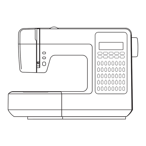
Page 4: Out Look
2. Out look Model 9300A Model 9300A2... -
Page 5: Names Of Principal Parts
3. Names of principal parts Model Model 9300A 9300A2 16 (A) 17 (B) 18 (C) 1. Tension dial 2. Bobbin thread guide 3. Upper thread guide 4. Thread take-up lever 5. Face plate 6. Needle up/down position button 7. Auto-lock button 8. -
Page 6: Names Of Electronic Parts
Names of e lectronic parts 9300A2 9300A Slide volume DC motor 2-A. Pulse motor (zigzag) Foot controller connector 2-B. Photo sensor complete (zigzag) 10-A. Pulse motor (stitch length) 3-A. Photo sensor complete 10-B. Photo sensor complete (needle position) (stitch length) 3-B. -
Page 7: Removing Methods Of External Parts
5. Removing methods of external parts 5-1 Face plate Remove screw (a) and remove the face plate. Face plate 5-2 Arm top cover Arm top cover Remove 2 screws (b, c) and remove the arm top cover. (2) 5-3 Sewing table complete Keep the snap-in sewing table horizontal, and pull it in the direction of the arrow. -
Page 8: Belt Cover
5-5 Belt cover - Remove screw (i) and remove belt cover. (5) Belt cover 5-6 Free arm cover Remove 2 screws (j, k) and remove the free arm cover. (6) Free arm cover 5-7 Free arm foot bush Remove 4 screws (l, m, n, o) and remove the Free arm foot bush free arm foot bush. -
Page 9: Front Cover
- Loosen screw (r) about 3mm. (9) - Loosen screw (s) about 3mm. (10) Note 1: First using electric torch (flash light) etc to locate screw (s) position which deeply inside the machine. - Remove screw (t). (11) - Remove front cover following direction of arrow. -
Page 10: Back Cover
5-9 Back cover - Remove front cover first. - Remove 2 screws (u, v). (13) Back cover - Loosen screw (w) about 3mm. (14) - Remove screw (x). - Loosen screw (y) about 3mm. - Remove the back cover. (15) -
Page 11: Adjusting Methods Of Each Part
6. Adjusting methods of each part 6-1 Symbol instructions Noise occur while the machine is running. Skip-over stitching, needle breakage, and problems associated with needle. Delivery of cloth to be in disorder and insufficient, problems associated with delivery amount. Stitch tightening problem. BH right and left stitching is not even, incorrect length and problems associated with buttonhole sewing. -
Page 12: Play Of Arm Shaft
6-2 Play of arm shaft 1) Remove the face plate and arm top cover. 2) Remove the 2 screws (a, b) of arm shaft collar (A). (1) 3) Pull hand wheel backward. 4) Push arm shaft collar (A) to left tightly against arm shaft bushing (B), and then fasten and secure screws (a, b). -
Page 13: Height Of Presser Foot
6-4 Height of presser foot 1) Remove face plate and lift up presser bar lifter lever (A). (1) 2) Loosen screw (a) of presser bar bracket. 3) Place gauge (B) (6.0~6.2mm) on top of needle plate. (3) 4) Pull down presser bar lifter lever so bottom of presser foot and top surface of gauge would meet. -
Page 14: Needle Flow At Maximum Zigzag Width
6-5 Needle flow at maximum zigzag width - Choose patterns #5, zigzag 7 mm. 1) Remove front cover. 2) Set needle bar at its lowest point when it swings to left. Turn hand wheel to move the needle bar upward. The vertical distance in which the needle point goes up at the left position from the top of the needle plate should be 5~10mm. -
Page 15: Drop Middle Point Of Needle
6-6 Drop middle point of needle - Choose patterns #1. 1) Remove face plate. 2) Loosen screw (a) of needle bar driving rod pin (b). (1) 3) Adjust needle by pushing (b) clockwise / counter-clockwise. 4) Make sure needle drops on middle of needle hole. -
Page 16: Needle Position Of Zigzag
6-7 Needle position of zigzag - Choose patterns #5, zigzag 7 mm. 1) Remove face plate 2) Loosen screw (a) of needle bar driving rod pin (b). (1) 3) Adjust needle by pushing (b) clockwise / counter-clockwise. Clockwise left Counter-clockwise right 4) Make sure needle drops on left / right of needle hole with even distance to the edge of needle hole, and then fasten the... -
Page 17: Automatic Needle Threader Adjustment
6-8 Automatic needle threader adjustment 1 Check the threader hook. If it is damaged, change new one. If it is inclined, adjust the threader hook Needle properly. 2 If the threader hook can not enter needle 0.1mm Threader hole freely, please adjust the threader hook stopper. -
Page 18: Adjustment Of Feed Rock Shaft And Feed Lifting Rock Cam
6-9 Adjustment of feed rock shaft and feed lifting rock cam 1) Remove cord reel cover, free arm base and free arm foot bush. 2) Turn the hand wheel to make the needle rise to its highest point. 3) Use the feed shaft test gauge (A) to check. -
Page 19: Height Of Needle Bar
6-10 Height of needle bar - Choose patterns #1. 1) Remove face plate and needle plate. 2) Remove the screws of rotary hook plate (A, B) and rotary hook plate, and take out the shuttle hook. 3) Put the gauge of height of needle 2.54~2.80 mm (D) into the shuttle hook holder, and turn the hand wheel to set the needle at the lowest point. -
Page 20: Timing Of Needle And Hook
6-11 Timing of needle and hook - Choose patterns #5, zigzag 7 mm. 1) Set the needle bar at its lowest point when it swings to the left. Place clamp (A) around the needle bar, tighten its screw (a) but still allowing movement. (1) 2) Place gauge (B) (4.0mm) between the needle bar support and clamp, tighten (A) until it is at its highest position, and... -
Page 21: Distance-Needle-Hook
6-12 Distance-needle-hook - Choose patterns #5, zigzag 7 mm. 1) Remove face plate and needle plate. Needle 2) Take off the shuttle hook. 3) Set the needle towards the lowest point of right side and lift it, make sure if The tip of hook space between needle and the tip of the s h u t t l e h o o k h o l d e r s h o u l d b e... -
Page 22: Play Between Shuttle Driver Shaft Gear And Lower Shaft Gear
6-13 Play between shuttle driver shaft gear and lower shaft gear 1) Remove free arm cover and needle plate. 2) Take off the shuttle hook. 3) Loosen three set screws (a,b,c) of the lower shaft gear (A) and move the lower shaft gear to right or left against axial direction. -
Page 23: Play Of Shuttle Driver Shaft
6-14 Play of shuttle driver shaft 1) Remove the needle plate. 2) There are 2 gauges (A, B) for testing the play of shuttle driver shaft. 3) When you turn the hand wheel counter- 0.5mm 0.3mm clockwise, the shuttle hook (C) will move to rotary hook plate (D), and generate the play between the shuttle hook and 1.0mm... -
Page 24: Feed-Dog Height
6-15 Feed-dog height 1) Remove free arm cover and lift needle to its highest position. 2) Remove presser foot. 3) Place setting gauge (A) (0.9~1.05mm) on needle plate. The feed dog height 0.9~1.05mm then can be checked. (1) 4) Press reverse button. At the correct height (0.9mm), the feed-dog will be moved freely forward and backward. -
Page 25: Position Of Feed-Dog In Relation To The Needle Plate (Left To Right)
6-16 Position of feed-dog in relation to the needle plate (left to right) 1) Remove the free arm cover and free arm foot bush. 2) Loosen the screw (a) of the feed crank shaft (A) that is on the right side. 3) Loosen the screw (b) of the feed crank shaft (B) that is on the left side. -
Page 26: Upper Thread Tension Adjustment
6-17 U p p e r t h r e a d t e n s i o n adjustment 1) Remove front cover and set dial tension (A) to "4". (1) 2) Use a dial tension gauge (150g) (B) to take measurement. -
Page 27: Shuttle Hook Tension Adjustment
6-18 S h u t t l e h o o k t e n s i o n adjustment 1) Remove the needle plate. 2) Use a dial tension gauge (50g) (A) to take measurement. (1) 3) Put dial tension thread into shuttle hook (the same way as inserting the bobbin) and pull it out, the standard range should be 13~17g. -
Page 28: Motor Belt Tension
6-19 Motor belt tension 1) Remove back cover and test tension of motor belt using belt tension gauge (A). Its standard measurement should be 100g. (1) 2) Adjusting the belt adjusting plate (B) to regulate the improper belt's tension. The way to adjust is as following: 4m/m Loosen the screw (a) of adjusting plate... -
Page 29: Drop Point Of Needle
6-20 Drop point of needle - Choose patterns #25. 1) Remove the cord reel cover. 2) To check if the feed rock crank (A), feed rock rod (B) and feed crank (C, D) are smooth. (1) 3) Place a piece of blank paper on top of needle plate and use presser foot to secure paper by pulling presser bar lifter lever down. -
Page 30: Adjustment Of Bh
6-21 Adjustment of BH 1) Remove the face plate. 2) To check if the overhead BH lever crank (A) and the photo sensor's (B) blocking movement were set in the middle place. 3) If it did not set in the middle place: Loosen 2 screws (a, b) of BH movement crank (C). -
Page 31: Bobbin Winding Problem
6-22 Bobbin winding problem 1) Place empty bobbin on spindle and push it to the right. 2) Put the thread into the spool rod, and put the spool rod cover on it. 3) Lead thread from spool to back side of thread guide (A) by following the indication. -
Page 32: Replace The Fuse
6-23 Replace the fuse Replacement of 9300A1: 1) Remove the front cover. 2) Remove the circuit board (A) by dismount the 4 screws (a, b, c, d) of the circuit board and cord. (1) 3) Flux the tin point of fuses (B, C) which are behind the circuit board, and replace the fuses (B, C). -
Page 33: Trouble Shooting Of Electrical Parts
7. Trouble shooting of electrical parts Model 9300A... - Page 34 7. Trouble shooting of electrical parts Model 9300A...
- Page 35 7. Trouble shooting of electrical parts Model 9300A2...
- Page 36 7. Trouble shooting of electrical parts Model 9300A2...
-
Page 37: Circuit Diagram
8. Circuit diagram 9300A Main board J1. DC motor J2. Feed stepper J3. Bight stepper J4. Tack switch board J5. Keyboard J6. Feed stepper detector J7. Bight stepper detector J8. Lamp J9. Bobbin winder switch J10. Button hole detector J11. Transformer J12. - Page 38 8. Circuit diagram 9300A Function diagram...
- Page 39 8. Circuit diagram 9300A Circuit diagram...
- Page 40 8. Circuit diagram 9300A2 Main board JP1.Keyboard JP2.LCD panel J1.Speed detector J2.Bight stepper detector J3.Needle position1 Main Board J4.Feed stepper detector J5.Needle position2 J6.Button hole detector J7.Foot control J8.DC motor J9.Lamp J10.Slide resistor J11.Bight stepper J12.Feed stepper J13.Transformer J14.Bobbin winder switch J15.Tack switch board BLUE GREEN...
- Page 41 8. Circuit diagram 9300A2 Function diagram...
-
Page 42: Circuit Diagram
8. Circuit diagram 9300A2 Circuit diagram... - Page 43 0301D3A01( ) May/05 9300A, 9300A2...
Need help?
Do you have a question about the 9300A and is the answer not in the manual?
Questions and answers