Table of Contents
Advertisement
Quick Links
Advertisement
Table of Contents

Summary of Contents for Hospitech Respiration AG100s
- Page 1 AG100s Operator's Manual...
- Page 2 SW version 2.3.2 Copyright © 2014 Hospitech Respiration Ltd. All rights reserved. Hospitech Respiration Ltd. reserves the right to make changes to its products or specifications to improve performance, reliability, or manufacturability. Information furnished by Hospitech Respiration Ltd. is believed to be accurate and reliable. However, Hospitech Respiration Ltd.
-
Page 3: Table Of Contents
High Voltage Hazards ..................12 MR Unsafe ......................12 Product Overview ....................13 Introduction.......................13 Descrip�on ......................13 Device Users ......................14 Indications for Use ....................14 Contra-indica�ons .....................14 AG100s System Components...................14 Control Unit Components .................16 The AG connec�on kit ..................17 Addi�onal Components ..................18 3.3.1 Cart......................18 3.3.2 Power Cord ....................18 3.3.3... - Page 4 Modes of Operation ..................24 4.3.1 Automatic Cuff Control (AnapnoGuard Tube) ...........24 4.3.2 Maintaining Cuff Control ................25 4.3.3 Standby ......................26 Operating The AG100s System ................27 Treatment Workflow..................27 System Operation....................28 5.2.1 Installation and Positioning ...............28 5.2.2 Power and Vacuum Source Connection ............29 5.2.3...
- Page 5 Instructions for se�ng a new default profile ...........57 Work Environment....................60 Environmental Conditions.................60 7.1.1 Ambient Opera�ng Temperature ..............60 7.1.2 Operating Pressure and Altitude ...............60 7.1.3 Ambient Humidity..................60 7.1.4 Storage and Transport Temperature (in original packaging) ....60 7.1.5 Storage and Transport Pressure and Altitude (in original packaging)..60 7.1.6 Storage and Transport Humidity (in original packaging) ......60 7.1.7...
- Page 6 ABBREVIATION LIST AnapnoGuard Endotracheal tube Graphic User Interface Intensive Care Unit...
-
Page 7: Before You Start
Read this manual to become familiar with all safety requirements and operating procedures before attempting to operate the system. ● The AG100s system may only be serviced by Hospitech Respiration Ltd. authorized personnel. Conventions Used in this Manual The following conventions in the form of notes, cautions and warnings are used... -
Page 8: Labels And Symbols
Labels and Symbols The following symbols appear on the AG100s system labels (control unit and AG connection kit): AG100s Main Label AG Connection Kit Label... - Page 9 Symbol Description Consult Operating Instructions Serial number Catalogue number LOT number Date of manufacture Manufacturer Protection From Electrical Shock CE Compliance Symbol CAUTION: Federal law restricts this device to sale by or on the order of a physician Discard Product After Expiration Date MM/YYYY Product was Sterilized by Ethylene Oxide Process...
-
Page 10: Safety Considerations
Single Use Only Authorized Representative in the European Union MR Unsafe Safety Considerations The AG100s system was designed to maximize safety for both patients and personnel. The following are some of the system's preventive safety measures: 1.3.1 Software Safety Features ●... -
Page 11: Intended Use Patient Popula�On
Intended Use Patient Population The AG100s is intended for pa�ents 18 years or older. General Precautions The following precautions must be observed to ensure safe use of the AG100s system. ● Read this manual thoroughly before attempting to operate the system. -
Page 12: High Voltage Hazards
High Voltage Hazards Warning The system utilizes high-voltage electricity. To avoid injury to personnel, do not operate the system before ensuring that the exterior panels are properly closed. Do not attempt to remove or disassemble the exterior panels. MR Unsafe Warning The system was not tested in MRI environment and thus is considered as MRI unsafe. -
Page 13: Product Overview
RODUCT VERVIEW Introduction The AG100s system is designed to provide cuff pressure control to all cuffed airways, and provide suction/evacuation of subglottic secretions from above the cuff, to all cuffed airways with a suction port. It also offers controlled suction capability for general use, e.g. -
Page 14: Device Users
(HCl). AG100 YSTEM OMPONENTS The AG100s system (figure 3.1) is comprised of the following two main components:... - Page 15 • The AG100s Control Unit • The AG connection kit comprised of Cassette and harness line tubes, for connecting the EndoTracheal tube and other Accessories to the AG100s control unit. Additional components: ● Cart (see Section 3.3.1) ● Power cord (see Section 3.3.2)
-
Page 16: Control Unit Components
Connection panel - for connecting the cassette to the control system. ● Piano valve – a mechanical valve used to configure the cassette routing of operational procedure. ● Operation buttons – Power On/Off and Stand By Figure 3-2: AG100s Control Unit... -
Page 17: The Ag Connec�On Kit
The AG connection kit The AG Connection Kit (figure 3.3) is designed to connect the AG100s control unit with the patient’s Endotracheal tube (ETT) and with the exterior accessory units (canister and saline bag) required for system operation. Warning The ETT is a disposable tube, meant for single use only. Do not reuse. -
Page 18: Addi�Onal Components
3.3.1 Cart The AG100s control unit is secured to the cart by leading rails mounted on the bottom of the AG100s control unit. The cart includes a bar for the saline bag and holder for the Canister. The cart wheels include brakes to prevent accidental movement. -
Page 19: Vacuum Inlet Connector
3.3.3 Vacuum Inlet Connector A designated vacuum inlet connector (figure 3-4) is supplied with the AG100s control unit. It is compatible with a ¼’’ ID tube which connects to the hospital’s vacuum source. Figure 3-4: Vacuum inlet connector 3.3.4 Air Filter A sterilized antibacterial hydrophobic air filter (figure 3-5) is supplied with the AG100s control unit and is situated on its back panel. -
Page 20: Saline Bag
3.3.6 Saline Bag When the AG100s system is used in conjunction with the AnapnoGuard Endo-tracheal tube (AG ETT) standard saline solution (0.9% NaCl concentration) is used for subglottic rinsing via the Vent line, while suction is performed via the Suction line. The rinsed saline and secretions suctioned from the subglottic space above the cuff are evacuated into the suction canister. -
Page 21: System Func�Onality
YSTEM UNCTIONALITY General Instructions The AG100s system supports use of all FDA cleared ETT’s, as well as the AnapnoGuard dedicated multi-purpose ETT. Table 2: System Functionality – ETT type comparison ETT TYPE AnapnoGuard Suction Standard --------------------- FUNCTIONS AG100s Automatic Cuff Control... -
Page 22: System Controls
This control is located on the bottom left corner of the system (figure 4-1) Standby Switches the system to Standby mode. This control is located on the bottom left side of the front door (figure 4-1). Figure 4-1: AG100s Mechanical Controls... - Page 23 4.2.2.2 Touchscreen Controls The AG100s display layout can be seen in figure 4-2. The touch screen includes the following controls: • Manual operation buttons – allows user to manually activate a procedure. • Settings button – refers the user to a settings menu where certain parameters can be changed for the current system run.
-
Page 24: Modes Of Operation
Modes of Operation The AG100s control system has two main operational modes and a Standby mode: 4.3.1 Automatic Cuff Control (AnapnoGuard Tube) The Automatic Cuff Control mode is the standard (default) mode for patients intubated with the AnapnoGuard endotracheal tube. -
Page 25: Maintaining Cuff Control
The basic concept of the Cuff Seal procedure (cuff pressure control closed loop based on CO measurements above the cuff) operates as described below (figure 4-4). Figure 4-4: Cuff Seal Procedure Flow Chart 4.3.2 Maintaining Cuff Control The Maintaining Cuff Control mode is available with all airways. Maintaining Cuff Control mode is the standard (default) operational setting for patients intubated with a Standard or Suction endotracheal tube. -
Page 26: Standby
4.3.3 Standby During the operation of the above documented modes, in cases of clinical intervention, temporary patient disconnection or any other cause for operator discretion, the system can be switched to Standby mode by pressing the Standby button (see figure 4-1). A popup Standby screen will then appear on the system screen (figure 5-25). -
Page 27: Operating The Ag100S System
AG100 PERATING YSTEM Treatment Workflow Installation and Positioning Power and Vacuum Source Connection System Initialization Automatic System Self-test Airway/Tube Selection System Parameters Selection Suction Tube Parameters AG Tube Parameters Standard Tube Parameters System Connections Saline Rinse Preparation Patient Connection Figure 5-1: Treatment Workflow... -
Page 28: System Operation
Slide the control unit sideways onto the cart’s top plate (figure 5-2), pulling the safety pin downwards (figure 5-3) until it clicks into place. Figure 5-2: Mounting the AG100s control unit onto cart Figure 5-3: Cart’s top plate safety pin... -
Page 29: 5.2.2 Power And Vacuum Source Connection
Warning To avoid the risk of electric shock, this equipment must only be connected to a supply mains with protective earth Figure 5-4: AG100s Control Unit – Back Panel 5.2.2.2 Vacuum Source Connection Connect the wall port’s vacuum tube to the system’s designated vacuum inlet located on the back panel (figure 5-4), via a designated connector (figure 5-5). -
Page 30: System Ini�Aliza�On
5.2.3 System Initialization Press the Power ON/OFF button located on the bottom left side of AG100s front panel (see figure 4-1). *The POWER LED, located on the system’s front panel, will turn ON with green light. System will turn ON and the Self-test screen will appear. -
Page 31: Tube Selec�On
5.2.5 Tube Selection The Tube Selection screen (figure 5-7) will now appear. Select the appropriate tube type (according to the tube type that was used to intubate the patient) by pressing one of the following options: AnapnoGuard Tube, Suction Tube or Standard Tube. Figure 5-7: Tube Selection 5.2.6 System Parameters Selection... -
Page 32: Patient Information Update
Table 3: System Parameters Configuration System Parameters Configuration AnapnoGuard Tube Screen Suction Tube Screen Standard Tube Screen 1. Select the minimum cuff 1. Select the 1. Select the required pressure for which the required cuff cuff pressure system is allowed to pressure (Cuff (Cuff Target automatically deflate the... -
Page 33: System Connections (Prior To Pa�Ent Connec�On)
5.2.8 System Connections (Prior to patient connection) The Saline and Canister Connections screen will appear (figures 5-10.a and 5-10.b). Follow the connection instructions displayed on the screen. For detailed connection instructions see Sections 5.2.8.1- 5.2.8.3 and figures 5.11-5.17 Figure 5-10.a: Connection Kit Installation Figure 5-10.b: Connection Kit Installation Screen for AnapnoGuard Tube Screen for Standard and Suction Tubes... - Page 34 5.2.8.1 Instructions for inserting and locking Cassette 1. Open the front door of the AG100s control unit (figure 5-11). Figure 5-11: Opening Front Door 2. Move the cassette locking lever to its down position (figure 5-12.B). Figure 5-12: Cassette locking lever: A. Up position (locked) B. Down position (unlocked) 3.
- Page 35 4. Connect the proximal end of the saline tube, protruding from the left side of the system, to the saline set’s valve. Note The above saline connection process is only relevant for use with The AG100s tube...
- Page 36 5.2.8.3 Instructions for Connecting the Suction Lines to the Canister 1. Connect the vacuum tube (WHITE connector) of the cassette extension harness to the canister’s vacuum entry point (figure 5-16). Figure 5-16: Canister vacuum line connection 2. Connect the patient tube (BLUE connector) of the cassette extension harness to the canister’s patient entry point (figure 5-17).
-
Page 37: Saline Rinse Preparation
Once all connections are in place, close the door and press Next to continue. The Checking Connections Screen will appear (figure 5-18). The system will run a connection check lasting approximately 1 min. When the procedure is complete, ‘OK’ will appear on the screen, and automatically the next screen will appear. - Page 38 In case saline does not appear in the canister, one of the following may have occurred: • The saline set’s roller clamp is closed. *In this case open it. • The saline set’s valve is improperly connected to the saline tube protruding from the left side of the system.
-
Page 39: Pa�Ent Connec�On
5.2.10 Patient Connection The Patient Connection screen will appear (figures 5-20 a-c). The image that appears on the screen depends on the tube type chosen during system initialization. Connect the AG Connection Kit cassette harness lines to the patient’s ETT in accordance with the instructions displayed on the screen. -
Page 40: System Modes (Once Patient Is Connected To The System)
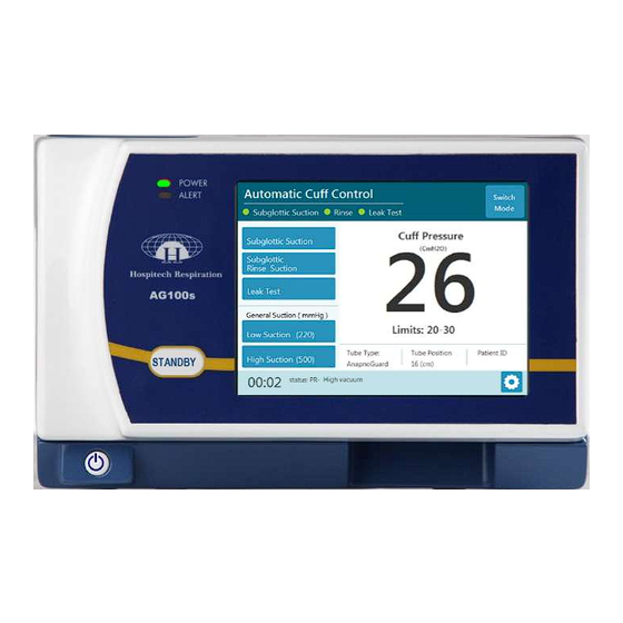
AG100s tube is utilized. The Automatic Cuff Control mode enables full functionality of the AG100s system. The AG100s system works in cycles. Each cycle runs for 30 minutes on average and contains the following procedures: a) Automatic adjustment of cuff pressure within preset limits - CO levels are measured during leak test every 2 minutes on average. - Page 41 Figure 5-22: Automatic Cuff Control Screen: AnapnoGuard tube 1. Cuff Pressure Window: Presents current Cuff Pressure (prominent number in bold) Indicates Cuff Pressure limits – the system automatically sets cuff pressure within predefined limits, according to detected leaks. 2. Tracheal operations performed during system operation: Subglottic Suction button –...
-
Page 42: Maintaining Cuff Control Mode
5.3.2 Maintaining Cuff Control Mode The Maintaining Cuff Control screen appears when: a) The patient has been intubated and connected to the AG control unit with the AnapnoGuard ETT. The patient is either being weaned and/or has gained semi or full consciousness, making it necessary to transfer them from Automatic Cuff Control mode, with its automated CO2 tracking and rinsing, to Maintaining Cuff Control mode where cuff pressure is kept stable and rinsing is disabled. - Page 43 Figure 5-23: Maintaining Cuff Control Screen: AnapnoGuard Tube 1. Cuff Pressure Window: Presents current Cuff Pressure (the prominent number in bold) Shows Target Pressure (the smaller bold number) - can be changed using the +/- buttons 2. Tracheal operations performed during system operation (or manually): Subglottic Suction button –...
- Page 44 5.3.2.2 Maintaining Cuff Control Mode (suction and standard tubes) When connecting the AG100s system to a suction or standard tube, the Maintaining Cuff Control Mode (figures 5-24.a and 5-24.b) enables the following operations: ● Maintains a fixed cuff pressure (suction and standard tubes) – the system keeps the cuff pressure stable at the target pressure chosen by the user ●...
-
Page 45: Standby
Standby Placing the system on Standby enables the user to: 1. Keep the patient connected to the system with fixed cuff pressure and no suctioning/rinsing. 2. Temporarily disconnect the patient from the system (e.g. for the purposes of treatment / examinations). 3. -
Page 46: Instructions For Temporarily Disconnecting And Reconnecting A Pa�Ent From The System
5.4.1 Instructions for Temporarily Disconnecting and Reconnecting a patient from the system 1. Press the Standby button. 2. Disconnect the Cassette harness lines from the patient’s ETT. Warning Do not unlock and remove the cassette from the system! Unlocking the cassette while the patient is still connected will cause the ETT’s cuff to deflate! 3. -
Page 47: Instructions For Replacing The Canister
5.4.2 Instructions for Replacing the Canister This procedure should be followed when a canister needs to be replaced (it is almost full or due to hospital requirements/protocols) 1. Press the Standby button. 2. Disconnect the suction lines from the canister. 3. -
Page 48: Instructions For Replacing The Saline Bag (Anapnoguard Tube Only)
5.4.3 Instructions for Replacing the Saline Bag (AnapnoGuard tube only) This procedure should be followed when a saline bag needs to be replaced (it is almost empty or due to hospital requirements/protocols) 1. Press the Standby button. 2. Disconnect the proximal end of the saline tube, which protrudes from the left side of the system, from the saline set. -
Page 49: Instructions For Replacing The Ag Connec�On Kit
3. Disconnect the suction lines from the canister and the saline tube from the saline set (if applicable). 4. Open the front door of the AG100s control unit (figure 5-11). 5. Lift the top panel of the saline pump (figure 5-15.B) and release the saline tube (figure 5-15.A). - Page 50 8. Dispose of the entire old AG connection kit. Warning The AG Connection Kit is a disposable kit, meant for single patient use only. Do not reuse on another patient. 9. Insert a new Cassette by sliding it into its cradle (figure 5-13). 10.
-
Page 51: Instructions For Changing Endotracheal Tube Type (Re-Intubation)
5.4.5 Instructions for Changing EndoTracheal Tube Type (Re- intubation) This procedure should be followed when a patient is re-intubated with a different tube type and the system needs to be updated with the change: 1. Press the Standby button. 2. Disconnect the Cassette harness lines from the patient’s ETT, and replace the ETT with a new one (re-intubation). -
Page 52: Instructions For Shutting Down The System (Permanent Disconnec�On)
5.4.6 Instructions for Shutting Down the System (Permanent Disconnection) 1. Press the Standby button. 2. Disconnect the cassette harness lines from the patient’s ETT. Warning Do not unlock and remove the cassette from the system! Unlocking the cassette while the patient is still connected will cause the ETT’s cuff to deflate! 3. - Page 53 6. Open the system’s front door. 7. Unlock and remove the Cassette. 8. Move the cassette locking lever back to its top position. 9. Close the front door of the AG100s control unit. 10. Dispose of the AG Connection Kit Warning The AG Connection Kit is a disposable kit, meant for single patient use only.
-
Page 54: Set�Ngs Menu
Settings Menu While the system is in operation, the user is able to review and change system parameters, patient details and general suction parameters that were configured during the Setup process, without performing the entire process again. The Settings menu is available at all times during system operation by pressing the Settings button in the bottom left corner of the Home Screen (see figure 4- •... - Page 55 Figure 5-29.b: System Parameters Figure 5-29.a: System Parameters Settings Settings Screen for AnapnoGuard tube Screen for AnapnoGuard tube From Automatic From Maintaining Cuff Control Mode Cuff Control Mode Figure 5-29.c: System Parameters Setting Figure 5-29.d: System Parameters Setting Screen for Suction tube Screen for Standard tube 1.
- Page 56 Figure 5-30: Patient details settings screen Figure 5-31: General suction settings screen Figure 5-32: Diagnostics screen...
-
Page 57: Setting Default Profile
ETTING EFAULT ROFILE Introduction To set a default profile that differs from the standardized manufacturing settings, authorized personnel can enter the Setting Default Profile Menu, and manually alter the system’s default profile parameters. Note Setting Profile Defaults should be performed while the patient is disconnected from the system The parameters displayed in the Setting Default Profile Menus (figures 6-3.a-c) differ depending on the tube type chosen. - Page 58 5. Enter user Password and press Next to continue (figure 6-2). Figure 6-2.a and Figure 6-2.b: Setting Default Profile: Enter Password Screens The Setting Default Profile screen will appear (figure 6-3.a). 6. The screen is loaded with the AG Tube Parameter Setting menu. Nevertheless, the user can choose a different menu (for a different tube type or for the General Suction function by pressing one of the tabs on the left side of the screen)
- Page 59 Figure 6-3.b: Default Parameter Settings Figure 6-3.c: Default Parameter Settings Screen for Suction Tube Screen for Standard Tube Figure 6-3.d: General Suction Default Parameter Settings When new default settings are saved, a green bar will appear (figure 6-3.e). Figure 6-3.e: Default Parameter Settings Screen- Default Settings Changed 8.
-
Page 60: Work Environment
NVIRONMENT Environmental Conditions 7.1.1 Ambient Operating Temperature ● 5-40⁰C / 41-104⁰F 7.1.2 Operating Pressure and Altitude ● Pressure: 700 hPa to 1060 hPa ● Altitude: -380m to 3,000m (-1250 ft. to 10,000 ft.) 7.1.3 Ambient Humidity ● 15 to 90% non-condensing 7.1.4 Storage and Transport Temperature (in original packaging) ●... -
Page 61: Life Time
AG100s Control Unit life time is 5 years. Shelf Life AG connection kit shelf life is 5 years. Sterility AG connection kit is supplied sterile and is intended for single patient use only. AG100s Control Unit is intended to be reused and treat multiple patients. -
Page 62: Maintenance And Preventive Inspec�On
REVENTIVE NSPECTION Introduction to Maintenance This chapter contains the maintenance instructions for the AG100s system. Routine maintenance may be performed by hospital staff unless otherwise specified. Any maintenance procedure not mentioned in this chapter must be performed only by Hospitech-authorized technical personnel. -
Page 63: Service Informa�On
Replacement of Disposable Components During routine use, as long as a patient is connected to the AG100s system, the AG connection kit should be replaced in accordance with the hospital policy for the replacement of ventilation and other tubing. -
Page 64: External Surface Cleaning
Whenever the AC cable requires cleaning use dry cloth. Make sure to unplug the cable before cleaning. Clean and disinfect the external surfaces of the AG100s control unit (including the rear side of the front door and the front panel behind the front door) using dedicated Pharma wipes, a lint-free cloth dipped in 70% isopropyl alcohol, or a hospital-grade disinfectant solution. -
Page 65: System Calibra�On
The user should track the “maintenance sticker” (Figure 8-1) located on the rear panel of the system to verify calibration validity date. In case validity is reaching expiration, user should contact Hospitech Respiration Ltd. support. GUI version: Firmware version:... -
Page 66: System Specifications
YSTEM PECIFICATIONS Technical specifications Table 5: Specification Parameters for AG100s Control Unit Parameter Specifications ● Medical grade Power Supply ● Isolating power-supply ● Input: 100V-240V ● Output: 24VDC, 3 A maximum current ● Width: 23 cm (9.1 in.) Size ● Depth: 24 cm (9.4 in.) ●... -
Page 67: Electrical Supply And Backup Battery
1 year Warranty Electrical Supply and backup battery The AG100s system requires a standard electrical supply of 100-240 VAC, 50/60 Hz. The system is connected to the clinic’s/hospital's main electrical supply system, and is protected from power failures by the clinic’s/hospital's redundancy power backup systems. -
Page 68: Emc Considera�Ons
• Connect the device into an outlet on a circuit different from that which was previously used. • Consult Hospitech Respiration Ltd. service personnel for help. Interference to the device may be caused by portable and mobile RF communication equipment. In case of an interruption, beware of such a device in the vicinity. - Page 69 Guidance and manufacturer’s declaration – electromagnetic emissions The AG100s System is intended for use in the electromagne�c environment specified below. The customer or the user of the AG100s System should assure that it is used in such an environment. Emissions test Compliance Electromagnetic environment –...
- Page 70 Guidance and manufacturer’s declaration – electromagnetic immunity The AG100s System is intended for use in the electromagne�c environment specified below. The customer or the user of the AG100s System should assure that it is used in such an environment. Immunity test...
- Page 71 Guidance and manufacturer’s declaration – electromagnetic immunity The AG100s System is intended for use in the electromagnetic environment specified below. The customer or the user of the AG100s System should assure that it is used in such an environment. IMMUNITY...
- Page 72 Recommended separation distances between portable and mobile RF communica�ons equipment and the AG100s System The AG100s System is intended for use in an electromagne�c environment in which radiated RF disturbances are controlled. The customer or the user of the AG100s System can help prevent electromagne�c interference by maintaining a minimum...
- Page 73 Table 10: IEC 60601-1-2 Guidance and manufacturer’s declaration – ENCLOSURE PORT IMMUNITY to RF wireless communications equipment. Test specifications for ENCLOSURE PORT IMMUNITY to RF wireless communications equipment Test Band Service Modula�on Maximum Distance IMMUNITY Compliance Frequency Power TEST LEVEL (MHz) Level (MHz)
- Page 74 5785 NOTE If necessary to achieve the IMMUNITY TEST LEVEL, the distance between the transmitting antenna and the AG100s System may be reduced to 1 m. The 1 m test distance is permi�ed by IEC 61000-4-3. a) For some services, only the uplink frequencies are included.
-
Page 75: International Standard Compliance
11 I NTERNATIONAL TANDARD OMPLIANCE The AG100s is designed to meet the following standards and regulations: Table 11: Applicable standards and regulations Descrip�on Standard Risk management for medical devices EN ISO 14971-1 (2012) Biological Evaluation of Medical Devices EN ISO 10993 1... - Page 76 Descrip�on Standard 15. Packaging materials and systems for medical devices EN 868-1:1997 which are to be sterilized. General requirements and test methods 16. Sterilization of medical devices. Requirements for EN 556: 2001 medical devices to be designated STERILE. Requirements for terminally sterilized medical devices 17.
-
Page 77: Alarm System And Troubleshooting
LARM YSTEM AND ROUBLESHOOTING The AG100s system is equipped with a self-testing software routine that continuously monitors system operation. If a system malfunction is detected, a display error message will appear on the touch-screen. Some of the more critical errors are combined with an auditory signal. The auditory signal can be inactivated by the user by pressing the audio alarm button (figure 12-1) located on the display error message (when applicable). - Page 78 Table 12: Error Messages and Troubleshooting Message Error Troubleshooting ● The vacuum is ● Verify that all the vacuum disconnected connections are connected ● OR to the system. ● The vacuum level ● Ensure that the vacuum supplied to the valve on the wall is open.
- Page 79 Cuff line is occluded Verify that the cuff line is not ● ● (by water droplets). blocked by droplets, or The system is obstructed due to kinks. ● attempting to clear the cuff line by raising the cuff pressure every 5 minutes.
- Page 80 The system has been Disconnect the harness from ● running for more than the patient the recommended Press the ON/OFF button to ● number of hours, and shut down the system. requires maintenance Contact a Hospitech ● representative for technical support.
Need help?
Do you have a question about the AG100s and is the answer not in the manual?
Questions and answers