Table of Contents
Advertisement
Advertisement
Table of Contents

Summary of Contents for VDH Products MC 785-SC
- Page 1 Operating Manual (Wall and panel mounting) Doc.nr.: 022091 MC 785-SC Step Control Description : Type: MANUAL Number of pages: Version: V2.3 File: Do022091 MC785-SC v23 EN.wpd Date: 19-10-2009 Software: MC785-SC V2.11 VDH Products BV - Roden - Holland Signed: File: Doc'02...
-
Page 2: Table Of Contents
Dimensions ..............31 The information contained in this document is assumed to be accurate. However VDH Products BV accepts no liability... -
Page 3: Technical Specifications
Version : V2.3 MC 785-SC Client : General Page : 3 of 32 Technical specifications General Type : MC 785-SC (Step-Control) Wall-mounting: Housing : Grey plastic Material : Polystyrol 454h KG 2 natur BASF Dimensions : 213 x 180 x 85mm (whd) -
Page 4: Inputs And Outputs
Relay-5 [05] programmable (NO/NC, 250Vac/10A not inductive) Functional specifications The MC 785-SC is an 8-stage step controller, which controls maximal 8 compressors and 8 condenser fans stepping up or down, based on the measured suction and discharge pressure and its setpoints. - Page 5 Operating manual Document nr. : 022091 Version : V2.3 MC 785-SC Client : General Page : 5 of 32 5 relay outputs and 2 analog outputs are standard on the MC785-SC, there are no digital inputs available, all other needed outputs can be obtained thru extra LMS-modules.
-
Page 6: Control
Operating manual Document nr. : 022091 Version : V2.3 MC 785-SC Client : General Page : 6 of 32 Control The MC785-SC is divided into two parts: on the left side is the compressor part (SUCTION) and on the right side is the condenser part (DISCHARGE). -
Page 7: The Suction Part (Compressor-Side)
Operating manual Document nr. : 022091 Version : V2.3 MC 785-SC Client : General Page : 7 of 32 The SUCTION part (compressor-side): Readout selection on the SUCTION display. By pressing the left SELECT key next to the SUCTION display once or more, the following values can be shown on the display: The suction pressure in Bars, LED Bar next to the display lights up. -
Page 8: The Discharge Part (Condenser-Side)
Operating manual Document nr. : 022091 Version : V2.3 MC 785-SC Client : General Page : 8 of 32 The DISCHARGE part (condenser-side): Readout selection on the DISCHARGE display. By pressing the right SELECT key next to the DISCHARGE display once or more, the following values can be shown on the display: The discharge pressure in Bars, LED Bar next to the display lights up. -
Page 9: Programming Internal Settings
Operating manual Document nr. : 022091 Version : V2.3 MC 785-SC Client : General Page : 9 of 32 Programming internal settings By pressing the PRG key for more than 5 seconds , the Internal Parameter Menu is entered. In the SUCTION display a P appears with a number behind it. - Page 10 Operating manual Document nr. : 022091 Version : V2.3 MC 785-SC Client : General Page : 10 of 32 P-Nr Description Range Unit fault P 30 Minimum adjustable pressure setpoint 0..50,0 Condenser P 31 Maximum adjustable pressure setpoint 0..50,0 50,0...
- Page 11 Operating manual Document nr. : 022091 Version : V2.3 MC 785-SC Client : General Page : 11 of 32 P-Nr Description Range Unit fault P 95 Outdoor temp. control active (0=no, 1=yes) 0..1 0 (no) P 96 Delta T condenser with outdoor temperature 1,0..50,0...
- Page 12 Operating manual Document nr. : 022091 Version : V2.3 MC 785-SC Client : General Page : 12 of 32 P-Nr Description Range Unit fault P130 0..6 Compressor-2 type: 0 = Not present 1 = On/off 2 = 2-Cylinder (0-50-100%) 3 = 3-Cylinder (0-33-66-100%)
- Page 13 Operating manual Document nr. : 022091 Version : V2.3 MC 785-SC Client : General Page : 13 of 32 P-Nr Description Range Unit fault P170 0..6 Compressor-4 type: 0 = Not present 1 = On/off 2 = 2-Cylinder (0-50-100%) 3 = 3-Cylinder (0-33-66-100%)
- Page 14 Operating manual Document nr. : 022091 Version : V2.3 MC 785-SC Client : General Page : 14 of 32 P-Nr Description Range Unit fault P210 0..6 Compressor-6 type: 0 = Not present 1 = On/off 2 = 2-Cylinder (0-50-100%) 3 = 3-Cylinder (0-33-66-100%)
- Page 15 Operating manual Document nr. : 022091 Version : V2.3 MC 785-SC Client : General Page : 15 of 32 P-Nr Description Range Unit fault P250 0..6 Compressor-8 type: 0 = Not present 1 = On/off 2 = 2-Cylinder (0-50-100%) 3 = 3-Cylinder (0-33-66-100%)
- Page 16 Operating manual Document nr. : 022091 Version : V2.3 MC 785-SC Client : General Page : 16 of 32 P-Nr Description Range Unit fault P310 0..2 Condenser-3 type: 0 = Not present 1 = On/off 2 = 2-Speed (0-50%-100%) P311 -- ..
- Page 17 Operating manual Document nr. : 022091 Version : V2.3 MC 785-SC Client : General Page : 17 of 32 P-Nr Description Range Unit fault P410 0..2 Condenser-8 type: 0 = Not present 1 = On/off 2 = 2-speed (0-50%-100%) P411 -- ..
-
Page 18: Table Of Assignment Of Relay Outputs
The 4- and 7-relay type LMS modules may be mixed together but at maximum 4 relay modules can be assigned. So at minimum there are 5 relays available on MC 785-SC and at maximum there are 5+4x7=33 relays available MC785-SC(5) + 4x LMS 7-RELAY MODULE. -
Page 19: Table Of Assignment Of Analog Outputs (0-10Vdc)
Operating manual Document nr. : 022091 Version : V2.3 MC 785-SC Client : General Page : 19 of 32 $) Table of assignment of analog outputs (0-10Vdc) Value Analog output number On Controller/Module Signal No output assigned Analog-output-1 MC785-SC regelaar... - Page 20 Operating manual Document nr. : 022091 Version : V2.3 MC 785-SC Client : General Page : 20 of 32 Value Digital input number On Controller/Module Input contact Digital input-1 LMS-dig-in-module-4 NO-C (make) Digital input-2 NO-C (make) Digital input-3 (JP1 without jumper and...
-
Page 21: Alarms
Operating manual Document nr. : 022091 Version : V2.3 MC 785-SC Client : General Page : 21 of 32 Alarms The following alarm messages may appear in the SUCTION-display: = Pressure sensor suction defect. Action: Everything off = Temperature sensor suction defect. -
Page 22: Function Flow
Operating manual Document nr. : 022091 Version : V2.3 MC 785-SC Client : General Page : 22 of 32 Function flow Operation of the Pband on the suction pressure side (Compressor-side): Overview of the function flow for 4-compressors for the switching up and down of compressors:... -
Page 23: Overview Of The Function Flow For Compressor With 5-Cylinders
Operating manual Document nr. : 022091 Version : V2.3 MC 785-SC Client : General Page : 23 of 32 Overview of the function flow for compressor with 5-cylinders: Working of compressor control with unequal steps; At maximum 70 control-steps can be made. This is f.i. 6 compressors (= 64 steps). - Page 24 Operating manual Document nr. : 022091 Version : V2.3 MC 785-SC Client : General Page : 24 of 32 Step Compressor-1, Compressor-2, Total 3-cylinder model 1kW 2-cyl.model 2kW 0-cyl. 1-cyl. 2-cyl. 3-cyl. 0-cyl. 1-cyl. 2-cyl. 0.33 0.33 0.66 0.66 0.33 1.33...
- Page 25 Operating manual Document nr. : 022091 Version : V2.3 MC 785-SC Client : General Page : 25 of 32 Step Compressor-1 Compressor-2 Compressor-3 Total on/off 1KW on/off 2KW on/off 4KW model model model x=on x=on x=on Example-3: overview of the control steps with the cooling capacity in percentages (x=active)
-
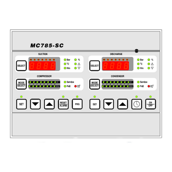
Page 26: Front View
Operating manual Document nr. : 022091 Version : V2.3 MC 785-SC Client : General Page : 26 of 32 Front view Front of MC 785-SC (wall mounting, drawing 001718) Front of MC 785-SC (panel mounting, drawing 021842) -
Page 27: Diagrams Of Connections
Operating manual Document nr. : 022091 Version : V2.3 MC 785-SC Client : General Page : 27 of 32 Diagrams of connections Connection diagram for MC 785-SC (wall mounting, drawing 001735) Connection diagram for RS485 network... - Page 28 Operating manual Document nr. : 022091 Version : V2.3 MC 785-SC Client : General Page : 28 of 32 Connection diagram for MC 785-SC (panel mounting drawing 021841)
- Page 29 Operating manual Document nr. : 022091 Version : V2.3 MC 785-SC Client : General Page : 29 of 32 Connection diagram for LMS-modules for MC785-SC drawing 001822...
- Page 30 Operating manual Document nr. : 022091 Version : V2.3 MC 785-SC Client : General Page : 30 of 32 Connections LMS 7x RELAY-SC MODULE (901.000409)
-
Page 31: 10. Dimensions
Operating manual Document nr. : 022091 Version : V2.3 MC 785-SC Client : General Page : 31 of 32 10. Dimensions Dimensions of MC785-SC panel mounting model drawing 940024... - Page 32 Operating manual Document nr. : 022091 Version : V2.3 MC 785-SC Client : General Page : 32 of 32 Dimensions of MC785-SC wall mounting drawing 961271...
Need help?
Do you have a question about the MC 785-SC and is the answer not in the manual?
Questions and answers