Table of Contents
Advertisement
Quick Links
Máquinas Gearless para Ascensor
WSG-S3
Instrucciones de funcionamiento
Traducción de las instrucciones de funcionamiento originales
La reimpresión, la traducción y la reproducción de cualquier
forma, incluso a modo de extractos, exigen la autorización
por escrito de la empresa WITTUR Holding GmbH.
Reservado el derecho a realizar modificaciones.
Máquinas Gearless para Ascensor
servogearless
WSG-S3.4
WSG-S3.5
WSG-S3.6
WITTUR Holding GmbH
Rohrbachstraße 26-30 • D-85259 Wiedenzhausen, Germany
Tel. +49 (0) 81 34/18-0 • Fax +49 (0) 81 34/18-49
http://www.wittur.com, E-mail: info@wittur.com
Código
Fecha
Versión
Página
eco
Nos reservamos el derecho de realizar modificaciones en
la información y las ilustraciones presentadas en estas
instrucciones de funcionamiento.
Reservado el derecho a realizar modificaciones.
ES
GM.8.002618.ES
03.06.2016
0.21
1
Advertisement
Chapters
Table of Contents

Related Manuals for WITTUR WSG-S3.4


Summary of Contents for WITTUR WSG-S3.4
- Page 1 Nos reservamos el derecho de realizar modificaciones en forma, incluso a modo de extractos, exigen la autorización la información y las ilustraciones presentadas en estas por escrito de la empresa WITTUR Holding GmbH. instrucciones de funcionamiento. Reservado el derecho a realizar modificaciones.
- Page 2 WSG - S3.4 - ..WSG - S3.5 - ..WSG - S3.6 - ..WITTUR Electric Drives GmbH se reserva el contenido de corregir o modificar el contenido y la información de productos sin previo aviso. También nos reservamos expresamente el derecho de realizar modificaciones técnicas...
-
Page 3: Table Of Contents
Máquinas Gearless para Ascensor Código GM.8.002618.ES Fecha 03.06.2016 WSG-S3 Versión 0.21 Instrucciones de funcionamiento Página Índice 1. Información general ..........................4 1.1. Acerca de estas instrucciones de funcionamiento ......... .4 1.2. -
Page 4: Información General
Máquinas Gearless para Ascensor Código GM.8.002618.ES Fecha 03.06.2016 WSG-S3 Versión 0.21 Instrucciones de funcionamiento Página Información general 1.1. Acerca de estas instrucciones de funcionamiento Las presentes instrucciones de funcionamiento sirven para trabajar de forma segura en maquinas WSG-S3. Considérelas parte del producto y consérvelas en un lugar fácilmente accesible. Todas las personas que trabajan en y con tornos elevadores WSG-S3 deben haber leído y comprendido estas instrucciones de funcionamiento. -
Page 5: Disposición De Las Indicaciones De Seguridad
Máquinas Gearless para Ascensor Código GM.8.002618.ES Fecha 03.06.2016 WSG-S3 Versión 0.21 Instrucciones de funcionamiento Página Personal cualificado Todos los trabajos de planificación, instalación y mantenimiento deben ser realizados únicamente por personal formado teniendo en cuenta las normas vigentes. El personal debe contar con la cualificación necesaria para la actividad en cuestión y de haber sido encargado para la instalación, el montaje, la puesta en funcionamiento y la operación del producto. -
Page 6: Descripción Del Producto
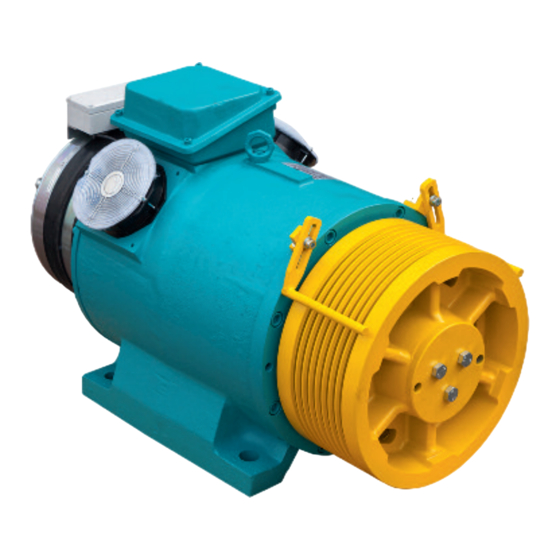
Máquinas Gearless para Ascensor Código GM.8.002618.ES Fecha 03.06.2016 WSG-S3 Versión 0.21 Instrucciones de funcionamiento Página Descripción del producto Los tornos elevadores sincrónicos compactos y sin engranajes WSG-S3 están construidos para elevadores de poleas de traccion. Se caracterizan por una elevada eficiencia, un nivel de ruido extremadamente bajo y unas propiedades de sincronismo excelentes. -
Page 7: Transporte Y Almacenamiento
Máquinas Gearless para Ascensor Código GM.8.002618.ES Fecha 03.06.2016 WSG-S3 Versión 0.21 Instrucciones de funcionamiento Página Transporte y almacenamiento • Todos los tornos elevadores salen en perfecto estado de la planta tras su comprobación. • Después del suministro, inspeccione la máquina en busca de daños externos. Si observara defectos relacionados con el transporte, habrá... -
Page 8: Instalación
Máquinas Gearless para Ascensor Código GM.8.002618.ES Fecha 03.06.2016 WSG-S3 Versión 0.21 Instrucciones de funcionamiento Página Instalación 5.1. Colocación En general, hay tener en cuenta que los bastidores o las bases en los que se instalan tornos Peligro elevadores deben ser comprobados mediante cálculos. •... -
Page 9: Conexión Eléctrica
Máquinas Gearless para Ascensor Código GM.8.002618.ES Fecha 03.06.2016 WSG-S3 Versión 0.21 Instrucciones de funcionamiento Página Condiciones del entorno • Las siguientes condiciones ambientales deben cumplirse en el lugar de instalación: Altura de instalación: máx. 1.000 m sobre el nivel del mar Temperatura ambiental: de -5 °C a 40 ºC Humedad relativa del aire: 85 % a 20 °C (sin condensación) -
Page 10: Conexión Del Motor/Protección Del Devanado
Máquinas Gearless para Ascensor Código GM.8.002618.ES Fecha 03.06.2016 WSG-S3 Versión 0.21 Instrucciones de funcionamiento Página 5.2.2. Conexión del motor/protección del devanado • La conexión eléctrica del motor, del freno y del control del devanado se realiza en la caja de bornes en la máquina. - Page 11 Máquinas Gearless para Ascensor Código GM.8.002618.ES Fecha 03.06.2016 WSG-S3 Versión 0.21 Instrucciones de funcionamiento Página Sección de cable necesaria: Las corrientes indicadas en los datos de la máquina hacen referencia al modo de funcionamiento S3-40%. Esto se debe considerar sin falta en la selección de la sección de cable necesaria. El valor efectivo permanente necesario de la corriente para la selección de cables Corriente máxima Corriente nominal...
-
Page 12: Sistema De Medición De Revoluciones/Posición
Máquinas Gearless para Ascensor Código GM.8.002618.ES Fecha 03.06.2016 WSG-S3 Versión 0.21 Instrucciones de funcionamiento Página 5.2.3. Sistema de medición de revoluciones/posición • La versión básica de los tornos elevadores se equipa con un encoder Sin-Cos Sendix 8.5873 de la empresa Kübler. La conexión se realiza mediante un cable de conexión de 10 m con extremos de hilos abiertos (sin conector). -
Page 13: Freno
Máquinas Gearless para Ascensor Código GM.8.002618.ES Fecha 03.06.2016 WSG-S3 Versión 0.21 Instrucciones de funcionamiento Página 5.2.4. Freno • ¡Preste también atención las instrucciones de funcionamiento del freno! • La alimentación de tensión continua a los frenos parciales se realiza mediante rectificadores de sobreexcitación que se suministran separados o en la caja de bornes del motor. - Page 14 Máquinas Gearless para Ascensor Código GM.8.002618.ES Fecha 03.06.2016 WSG-S3 Versión 0.21 Instrucciones de funcionamiento Página Control de los frenos • El control del estado de conmutación de los frenos se realiza con ayuda de microconmutadores protegidos contra el polvo con contactos de oro. Está disponible como conexión tanto de "contacto de reposo" como de "contacto de trabajo".
- Page 15 Máquinas Gearless para Ascensor Código GM.8.002618.ES Fecha 03.06.2016 WSG-S3 Versión 0.21 Instrucciones de funcionamiento Página Propuesta de conmutación para la activación de freno WSG-S3 Reservado el derecho a realizar modificaciones. Reservado el derecho a realizar modificaciones.
-
Page 16: Puesta En Funcionamiento
Máquinas Gearless para Ascensor Código GM.8.002618.ES Fecha 03.06.2016 WSG-S3 Versión 0.21 Instrucciones de funcionamiento Página Puesta en funcionamiento Los siguientes puntos deben controlarse y ejecutarse: • ¿Coinciden todas las indicaciones de potencia/aplicación en la máquina con el caso de aplicación? •... -
Page 17: Operación Y Mantenimiento
Máquinas Gearless para Ascensor Código GM.8.002618.ES Fecha 03.06.2016 WSG-S3 Versión 0.21 Instrucciones de funcionamiento Página Operación y mantenimiento 7.1. Generalidades • Deben acatarse indispensablemente las normas sobre el funcionamiento, el mantenimiento y la inspección conforme a las disposiciones de seguridad vigentes de la construcción del elevador como, entre otras, DIN EN 81-20, DIN EN 81-50, LD 2014/33/EU así... -
Page 18: Lubricación Adicional De Los Cojinetes
Máquinas Gearless para Ascensor Código GM.8.002618.ES Fecha 03.06.2016 WSG-S3 Versión 0.21 Instrucciones de funcionamiento Página 7.3. Lubricación adicional de los cojinetes Una lubricación adicional del cojinete principal se requiere después de unas 7.000 horas de funcionamiento. Como grasa para cojinetes se utiliza una grasa KP 2 N-30 conforme a DIN 51 502 (por ejemplo Wälalit LZ 2 o Klüberlub BE 41-542 (aprox. -
Page 19: Cambio De Poleas De Traccion
Máquinas Gearless para Ascensor Código GM.8.002618.ES Fecha 03.06.2016 WSG-S3 Versión 0.21 Instrucciones de funcionamiento Página 7.5. Cambio de poleas de traccion Advertencia La polea de traccion puede soltarse si no está montada correctamente. Herramientas necesarias • Dispositivo elevador • Pieza distanciadora (15...20 mm) •... -
Page 20: Evacuación De Emergencia
Máquinas Gearless para Ascensor Código GM.8.002618.ES Fecha 03.06.2016 WSG-S3 Versión 0.21 Instrucciones de funcionamiento Página 7.6. Evacuación de emergencia Las medidas para la evacuación de emergencia solo deben ser realizadas por personal Peligro cualificado para el mantenimiento del elevador. Evaluación de emergencia manual •... - Page 21 Máquinas Gearless para Ascensor Código GM.8.002618.ES Fecha 03.06.2016 WSG-S3 Versión 0.21 Instrucciones de funcionamiento Página • Para casos como avería o inmovilización en estado suspendido se puede utilizar un dispositivo de retorno mecánico para desplazar a mano el elevador. El uso del dispositivo de retorno puede verse en el dibujo.
-
Page 22: Comprobación Del Freno Conforme A En 81
Máquinas Gearless para Ascensor Código GM.8.002618.ES Fecha 03.06.2016 WSG-S3 Versión 0.21 Instrucciones de funcionamiento Página 7.7. Comprobación del freno conforme a EN 81 La comprobación del freno debe realizarse si la cabina se encuentra cerca del centro del hueco. Las eventuales conmutaciones de cortocircuito del motor existentes deben desactivarse para comprobar únicamente la acción del freno. -
Page 23: Sustitución Del Encoder
Máquinas Gearless para Ascensor Código GM.8.002618.ES Fecha 03.06.2016 WSG-S3 Versión 0.21 Instrucciones de funcionamiento Página 7.8. Sustitución del encoder El encoder solo está accesible desde la parte trasera del motor. ¡Preste atención a las instrucciones de montaje del sistema de medición Kübler! El encoder solo debe desmontarse cuando ello sea necesario a causa de un defecto. -
Page 24: Localización De Fallos
Máquinas Gearless para Ascensor Código GM.8.002618.ES Fecha 03.06.2016 WSG-S3 Versión 0.21 Instrucciones de funcionamiento Página 7.9. Localización de fallos Fallo Causa Solución El motor no funciona o funciona • Fases del motor no conectadas correcta- • Conectar correctamente las fases del motor de forma descontrolada o no genera mente •... -
Page 25: Clave De Tipo
Máquinas Gearless para Ascensor Código GM.8.002618.ES Fecha 03.06.2016 WSG-S3 Versión 0.21 Instrucciones de funcionamiento Página Clave de tipo Ejemplo: 4 0 A . Z3 - X3 X4 X5 X6 X7 X8 X9 Designación específica del cliente S = Motor sincrónico G = sin engranajes U = sin engranajes, con homologación UL/CSA... -
Page 26: Datos Técnicos
10 mA Vida útil mecánica de los 2 x 10 conmutaciones contactos : Ventilador externo (1 x para WSG-S3.4/5 y 2 x para WSG-S3.6) Tipo: W2E 142-BB01-01 Tensión de funcionamiento: 230 V / 50/60 Hz Consumo de corriente: 0.12/0.13 A Reservado el derecho a realizar modificaciones. - Page 27 Máquinas Gearless para Ascensor Código GM.8.002618.ES Fecha 03.06.2016 WSG-S3 Versión 0.21 Instrucciones de funcionamiento Página WSG-S3.4 WSG-S3.5 WSG-S3.6 Motor [Nm] Par de giro S3-40%, 240 S/h 1200 1650 [Nm] Par de giro máx.: 1800 2400 3200 [Nm] Momento de frenado:...
-
Page 28: Esquema De Dimensiones
Máquinas Gearless para Ascensor Código GM.8.002618.ES Fecha 03.06.2016 WSG-S3 Versión 0.21 Instrucciones de funcionamiento Página 10. Esquema de dimensiones 87.5 max. 4 orificios de fijación Ø 35 y 6 orificios roscados M 30 Con ventilación manual montada el motor se prolonga en 39 mm. WSG- S3.4 S3.5... -
Page 29: Accesorios
Máquinas Gearless para Ascensor Código GM.8.002618.ES Fecha 03.06.2016 WSG-S3 Versión 0.21 Instrucciones de funcionamiento Página 11. Accesorios 11.1. Cables de conexión para sistemas de medición Convertidor tipo Sistema de medi- Cable recomendado del ción recomendado sistema de medición E-Pack ECN 413 503 325 021 xx (EnDat / SSI) Arkel ARCODE... -
Page 30: Juego De Cables De Conexión Para Motor Y Freno
Máquinas Gearless para Ascensor Código GM.8.002618.ES Fecha 03.06.2016 WSG-S3 Versión 0.21 Instrucciones de funcionamiento Página 11.2. Juego de cables de conexión para motor y freno 503 957 A21-xx Cable de motor 503 957 A21-xx-1 Cable del sensor de temperatura 503 957 A21-xx-2 Cable del ventilador Cable de freno (imán) 503 958-011-xx... -
Page 31: Ventilación Manual Del Freno
Máquinas Gearless para Ascensor Código GM.8.002618.ES Fecha 03.06.2016 WSG-S3 Versión 0.21 Instrucciones de funcionamiento Página 11.3. Ventilación manual del freno Bajo petición, el freno puede equiparse con un dispositivo de ventilación manual. Esto debe indicarse en el pedido. ¡No es posible un reequipamiento! El soporte de la palanca de mano necesario para ventilar el freno, incluido el cable Bowden, se puede suministrar conjuntamente si fuera necesario. -
Page 32: Repuestos
Máquinas Gearless para Ascensor Código GM.8.002618.ES Fecha 03.06.2016 WSG-S3 Versión 0.21 Instrucciones de funcionamiento Página 12. Repuestos Posición Pieza Denominación Motor polea de traccion según la placa indicadora de tipo de la máquina Clave de tipo X5X6X7 Sistema de medición (en función de la especificación) ECN 413 / SSI / 2048 incr. / aro de apriete ECN 413 / ENDAT / 2048 incr. - Page 38 Annex to the EC Type-Examination Certificate No. EU-BD 881 of 2016-03-18 Scope of application Use as braking device – part of the the protection device against overspeed for the car moving in upwards direction – permissible brake torque and tripping rotary speed 1.1.1 Permissible brake torque when the braking device acts on the shaft of the traction sheave while the car is moving upward...
- Page 39 Annex to the EC Type-Examination Certificate No. EU-BD 881 of 2016-03-18 Conditions Above mentioned safety component represents only a part at the protection device against over- speed for the car moving in upwards direction and unintended car movement. Only in combination with a detecting and triggering component in accordance with the standard (two separate compo- nents also possible), which must be subjected to an own type-examination, can the system created fulfil the requirements for a protection device.
- Page 40 Enclosure to the EU Type-Examination Certificate No. EU-BD 881 of 2016-03-18 Authorised Manufacturer of Serial Production – Production Sites (valid from: 2016-03-18): Company INTORQ GmbH & Co. KG Address Wülmser Weg 5 31855 Aerzen – Germany Company INTORQ (Shanghai) Co., Ltd. Address No.
- Page 42 setting the standard INTORQ BFK455-28 Electromagnetically Released Spring-Applied Brake Translation of the Original Operating Instructions www.intorq.com www.intorq.com...
- Page 43 This documentation applies to the: Product key INTORQ Legend for the product key INTORQ BFK455 Product group Brakes Product type Spring-applied brake Type Size Not coded: Supply voltage, hub bore, options INTORQ | BA 14.0196 | 04/2016...
- Page 44 Identification Packaging label Example Manufacturer Type number Type (see product key) Bar code Designation Qty. per box Rated/holding voltage Rated torque Rated/holding power Hub diameter Packaging date Model identification CE mark Note Name plate Example Manufacturer CE mark Type (see product key) EC-type examination identification Rated/holding voltage Rated/holding power...
- Page 45 Document history Material number Version Description 33000756 05/2011 TD09 First edition 33000756 05/2012 TD09 Change in telephone and fax number Front and back page new Addition of the EC type test number Supplemented by chapter “Project planning notes” Supplemented by chapter “Wear of spring-applied brakes” 33002468 03/2013 TD09 Amended by new chapter on manual release installation...
- Page 46 Contents Preface and general information .......................... 6 About these Operating Instructions ......................6 Terminology used ............................6 Conventions in use ............................6 Abbreviations used ............................7 Safety instructions and notices ........................8 Scope of delivery ............................9 Disposal ................................ 9 Drive systems .............................
-
Page 47: Preface And General Information
Preface and general information Preface and general information About these Operating Instructions ❚ These Operating Instructions will help you to work safely with the spring-applied brake with electromag- netic release. They contain safety instructions that must be followed. ❚ All persons working on or with the electromagnetically released spring-applied brakes must have the Op- erating Instructions available and observe the information and notes relevant for them. -
Page 48: Abbreviations Used
Preface and general information Abbreviations used Letter symbol Unit Designation Rated frictional force Current Holding current, at 20 °C and holding voltage Release current, at 20 °C and release voltage Rated current, at 20 °C and rated voltage Tightening torque of fixing screws Braking torque at a constant speed of rotation Rated torque of the brake, rated value at a relative speed of rotation of 100 rpm... -
Page 49: Safety Instructions And Notices
Preface and general information Letter symbol Unit Designation Delay during engagement (time from switching off the supply voltage to the beginning of the torque rise) Rise time of the braking torque, time from the start of torque rise until reaching the braking torque Over-excitation time Voltage V DC... -
Page 50: Scope Of Delivery
Preface and general information Danger level DANGER DANGER indicates a hazardous situation which, if not avoided, will result in death or serious injury. WARNING WARNING indicates a potentially hazardous situation which, if not avoided, could result in death or serious injury. CAUTION CAUTION indicates a hazardous situation which, if not avoided, could result in minor or mod- erate injury. -
Page 51: Drive Systems
Preface and general information Drive systems Labelling Drive systems and components are unambiguously designated by the indications on the nameplate. Manufacturer: INTORQ GmbH & Co. KG, Wülmser Weg 5, D-31855 Aerzen, Germany ❚ The spring-applied INTORQ brake is also delivered in single modules which can then be put together by the customer according to their requirements. -
Page 52: Safety Instructions
Safety instructions Safety instructions General safety instructions ❚ INTORQ components: ... must only be used as directed..must not be commissioned if they are noticeably damaged..must not be technically modified..must not be commissioned if they are incompletely mounted or connected.. -
Page 53: Application As Directed
Safety instructions Application as directed ❚ INTORQ components: ... are intended for use in machinery and systems..must only be used for the purposes ordered and confirmed..must only be operated under the ambient conditions prescribed in these Operating Instructions.. -
Page 54: Technical Specifications
Technical specifications Technical specifications Product description Versions Basic module Fig. 1 Design of a BFK455 spring-applied brake 1.1 Stator Complete rotor Flange 1.2 Pressure springs Coil Armature plate Shaft 13 Cover ring INTORQ | BA 14.0196 | 04/2016... - Page 55 Technical specifications 3.1.1 General information The spring-applied brake is designed for converting mechanical work and kinetic energy into heat energy. Due to the static braking torque, loads can be held at standstill. Emergency braking is possible at high speed of rotation. The wear increases as the switching energy increases (operating speeds 17).
- Page 56 Technical specifications 3.1.3 Brake release When the brakes are applied, an air gap “s ” is present between the stator (1.1) and the armature plate (2). To release the brake, the coil of the stator (1.1) is energised with the DC voltage provided. The resulting mag- netic flux works against the spring force to draw the armature plate (2) to the stator (1.1).
-
Page 57: Rated Data
Technical specifications Rated data 3.2.1 Dimensions s LN s LN Type Rated torque Air gap Permitted Rotor thickness Weight wear complete stator +0.05 [mm] [NM] [mm] [mm] min. [mm] max. [mm] m [kg] Lmax. 2 x 1100 2 x 1200 17.7 BFK455-28 2 x 1700... -
Page 58: Rated Data (Design Data)
Technical specifications 3.2.2 Electrical data Type Voltage Power Coil resistance Current Release ±10% Holding ±10% Brake release Holding [V DC] [V DC] ± 5% [] 2 x 24.5 2 x 4.21 BFK455-28 2 x 434 2 x 108.5 2 x 97 2 x 2.12 2 x 298.6 2 x 1.21... - Page 59 Technical specifications Type Max. Transitional Rated torque Switching times [ms] Max. speed permitted switching at s and 0.7 I switching frequency energy Engaging DC side Disengaging max. [Nm] [1/h] [rpm] 2 x 1100 2 x 1200 BFK455-28 2 x 1700 360000 2 x 1800 2 x 2065...
-
Page 60: Switching Energy / Switching Frequency
Technical specifications Switching energy / switching frequency Fig. 3 Switching energy as a function of the switching frequency Switching energy Q [J] Switching frequency S [1/h] – S hue ------------------ - S hue – ------------------------------- - Q smax Q E 1 e... -
Page 61: Emissions
Technical specifications Emissions Electromagnetic compatibility NOTICE The user must ensure compliance with EMC Directive 2014/30/EU using appropriate controls and switching devices. If an INTORQ rectifier is used for the DC switching of the spring-applied brake: If the switching frequency exceeds five switching operations per minute, the use of a mains filter is required. If the spring-applied brake uses a rectifier from another manufacturer for the switching, it may become nec- essary to connect a spark suppressor in parallel with the AC voltage. -
Page 62: Mechanical Installation
Mechanical installation Mechanical installation Important notes NOTICE The toothed hub and screws must not be lubricated with grease or oil. Necessary tools Type Torque wrench Open-jawed spanner Bit for hexagon socket screws Measuring range [Nm] Wrench width [mm] Adjustment tubes - wrench size [mm] BFK455-28 40 - 400... -
Page 63: Assembly
Mechanical installation Assembly 4.3.1 Important notes Brake size Minimum requirements: Use as counter friction surface Material Evenness Axial Roughness Miscellaneous [mm] run-out [mm] ❚ Threaded holes with mini- S235 JR < 0.1 Rz10 mum thread depth EN-GJL-250 ❚ Free of grease and oil Tab. -
Page 64: Installation
Mechanical installation Installation NOTICE The toothed hub and screws must not be lubricated with grease or oil. NOTICE When you have ordered a version with flange, attach the hub first ( 23), then continue with the “Assembly of the counter friction faces”. 4.4.1 Brake assembly Mounting the first hub onto the shaft... - Page 65 Mechanical installation Assembly of the counter friction faces Flange (option) Fig. 5 Assembly of the flange 15 End shield Flange 4. Hold the flange (6) to the end shield (15). 5. Align the through holes in the flange to the threads of the fastening bore holes. In the following sections, only assembly for the version with flange will be described.
- Page 66 Mechanical installation NOTICE Only in the case of rotors with mounting paste on their gear teeth: ❚ Remove cover films from both front ends of the rotor. ❚ Protect friction surfaces against contact with mounting paste! ❚ After the mounting, excessive mounting paste must be removed properly! Installation of the second hub onto the shaft Fig.
- Page 67 Mechanical installation Assembly of the first stator Fig. 8 Assembly of the stator Stator, complete Flange Shaft 4.2 Circlip 15 End shield 10. Push the complete stator onto the shaft. 11. Align the through holes in the complete stator (1) to the threads of the fastening bore holes. Assembly of the second rotor Fig.
- Page 68 Mechanical installation NOTICE Only in the case of rotors with mounting paste on their gear teeth: ❚ Remove cover films from both front ends of the rotor. ❚ Protect friction surfaces against contact with mounting paste! ❚ After the mounting, excessive mounting paste must be removed properly! NOTICE If a manual release is to be installed, the procedure described in section 4.5.2 (Step 2) must be carried out now!
- Page 69 Mechanical installation 4.4.2 Check the air gap DANGER Danger: rotating parts! Switch off the voltage. The brake must be free of residual torque. s LN s LN Fig. 11 Check the air gap 1. Check the air gap near the screws (10) by means of a feeler gauge. Compare the measured values to the values for "s "...
-
Page 70: Manual Release
Mechanical installation 3. Slightly turn the sleeve bolts (9) using an open end spanner. If the air gap is too large, screw into the stator (1.1). If the air gap is too small, screw them out of the stator (1.1). A 1/6 turn will change the air gap by approximately 0.15 mm. - Page 71 Mechanical installation 4.5.2 Installing the manual release 12.1 Fig. 14 Applying the manual release lever 2. Put both levers completely (12.1) onto the second stator (1A). To do this, push in the plates' pins into the corresponding holes of the stator (using a suitable tool). NOTICE The plates are not symmetric.
- Page 72 Mechanical installation 4. From the armature plate end, plug one pair of pre-assembled tension rods (12.14) each into the provided bore holes (Ø11 mm) of the complete stator (1A). Insert the springs (12.5) of the tension rod into the clearing hole of the armature plate (Ø16.5 mm) in the process. Fig.
- Page 73 Mechanical installation 9. Establish the electrical connection and energize the brake ( 35). 10. Use a torque key to re-tighten the supplied fixing screws (10) with the required tightening torque 16). 11. Switch off the power. 4.5.3 Checking the air gap Fig.
- Page 74 Mechanical installation Fig. 19 Test dimensions and reference dimensions 16. Check of the correct setting (nominal dimension 1.05 ... 1.15 mm): For this purpose, position two feeler gauges of the same thickness (e.g. 1.1 mm) for each tension rod between the hexagon nuts and the complete stator and ensure that the feeler gauges can be easily moved.
-
Page 75: Cover Ring Assembly
Mechanical installation Cover ring assembly NOTICE Brakes without flange require a groove at the end shield for the lip of the cover seal. Fig. 20 Cover ring assembly Stator, complete Flange 13 Cover ring 1. Disconnect electrical connection. 2. Pull cables through the cover rings (13). 3. -
Page 76: Electrical Installation
Electrical installation Electrical installation Important notes DANGER There is a risk of injury by electrical shock! ❚ The electrical connections must only be made by skilled personnel! ❚ Only carry out connection work when no voltage is applied (no live parts)! There is a risk of unintended start-ups or electric shock. -
Page 77: Bridge/Half-Wave Rectifier (Optional)
Electrical installation 5.1.1 Switching suggestions 230 V AC or 400 V AC Brake circuit 1 Brake circuit 2 observe the observe the polarity polarity Suppressor Suppressor circuit circuit Brake Brake Fig. 21 INTORQ BFK455 connection diagram Switching on ❚ K2/K4 must be switched on before or at the same time as K1/K3! Switching off ❚... - Page 78 Electrical installation 5.2.1 Assignment: Bridge/half-wave rectifier - brake size Rectifier type Supply voltage Coil voltage Assigned brake Release / holding [V AC] [V DC] BFK455-28 (205 V) BEG-561-255-130 ±10% 205 / 103 360 / 180 BFK455-28 (360 V) BEG-561-440-130 ±10% 5.2.2 Technical specifications Rectifier type...
-
Page 79: Electrical Connection
Electrical installation 5.2.3 Permissible current load at ambient temperature 1 For screw assembly with metal surface (good heat dissipation) 2 For other assembly (e.g. adhesive) Electrical connection DANGER There is a risk of injury by electrical shock! The brake must only be electrically connected when no voltage is applied! NOTICE Compare the coil voltage of the stator to the DC voltage of the installed rectifier. -
Page 80: Commissioning And Operation
Commissioning and operation Commissioning and operation Important notes DANGER ❚ The live connections and the rotating rotor must not be touched. ❚ The drive must not be running when checking the brake. Function checks before commissioning 6.2.1 Functional checks Brake with micro-switch DANGER Danger: rotating parts! The brake must be free of residual torque. -
Page 81: Commissioning
Commissioning and operation 6. Measure the DC voltage at the brake: The measured DC voltage after the over-excitation time (see bridge/half-wave rectifier, must correspond to the holding voltage (see table 5). A deviation of ±10 % is permissible. 7. Check the air gap “s ”. -
Page 82: During Operation
Commissioning and operation During operation DANGER Danger: rotating parts! The running rotor must not be touched. DANGER There is a risk of injury by electrical shock! Live connections must not be touched. ❚ Checks must be carried out regularly. Pay special attention to: unusual noises or temperatures loose attachment elements the condition of the electrical cables... -
Page 83: Maintenance And Repair
Maintenance and repair Maintenance and repair Wear of spring-applied brakes INTORQ spring-applied brakes are wear-resistant and designed for long maintenance intervals. The friction lining and braking mechanism are subject to operational wear. For safe and trouble-free operation, the brake must be checked at regular intervals or replaced, if necessary NOTICE The air gap must not be re-adjusted after it has been correctly adjusted during the initial installation of the brake on the motor! This could result in a loss of braking torque. -
Page 84: Inspections
Maintenance and repair Inspections To ensure safe and trouble-free operations, the spring-applied brakes must be checked at regular intervals and, if necessary, replaced. Servicing will be easier at the plant if the brakes are made accessible. This must be considered when installing the drives in the plant. Primarily, the required maintenance intervals for industrial brakes result from their load during operation. -
Page 85: Maintenance
Maintenance and repair 7.2.2 Release / voltage 1. Start motor and control system! DANGER Danger: rotating parts! The running rotor must not be touched. DANGER There is a risk of injury by electrical shock! Live connections must not be touched. 2. - Page 86 Maintenance and repair 7.3.2 Check the air gap DANGER Danger: rotating parts! The motor must not run during the check. 1. Stop the motor and control system! 2. Measure the air gap “s ” near the fixing screws between the armature plate and the stator using a feeler gauge.
-
Page 87: Spare-Parts List
Maintenance and repair Spare-parts list ❚ Only parts with item numbers are available. The item numbers are only valid for the standard design. ❚ Please include the following information with the order: Order number of the brake Position number of the spare part Fig. -
Page 88: Ordering Spare Parts
Maintenance and repair Ordering spare parts Stator, complete Size 103 V / 52 V 205 V / 103 V 360 V / 180 V Voltage Nm (see torque gradation) Braking torque Standard (1000 mm) Cable length Standard Armature plate Monitoring the switching function Micro-switch Components Aluminium... -
Page 89: Troubleshooting And Fault Elimination
Troubleshooting and fault elimination Troubleshooting and fault elimination If any malfunctions should occur during operations, please check for possible causes based on the following table. If the fault cannot be fixed or eliminated by one of the listed measures, please contact customer ser- vice. - Page 90 Troubleshooting and fault elimination Fault Cause Remedy Rotor cannot rotate Air gap “s ” too small Readjust the air gap “s ” ( 28). freely Rotor thickness too Rotor has not been Replace the rotor ( 45). small replaced in time Voltage is not zero Incorrect micro-switch Check and correct the wiring of the micro-switch.
- Page 91 Notes Notes INTORQ | BA 14.0196 | 04/2016...
- Page 92 INTORQ GmbH & Co KG Germany PO Box 1103 D-31849 Aerzen Wülmser Weg 5 D-31855 Aerzen +49 5154 70534-444 +49 5154 70534-200 info@intorq.com INTORQ (Shanghai) Co., Ltd. No. 600, Xin Yuan Nan Road, Building No. 6 / Zone B Nicheng town, Pudong 201306 Shanghai ...
Need help?
Do you have a question about the WSG-S3.4 and is the answer not in the manual?
Questions and answers