Table of Contents
Advertisement
Advertisement
Table of Contents

Summary of Contents for AGCO EDT
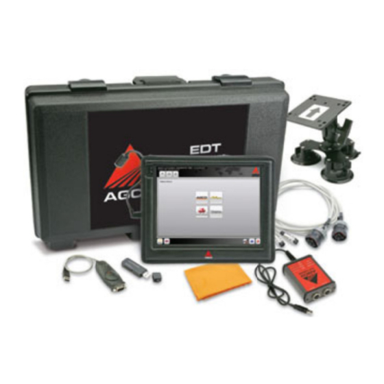
- Page 1 SERVICE TOOL OPERATOR MANUAL Electronic Diagnostic Tool (EDT) 22.01.2014...
-
Page 3: Table Of Contents
Software Updating ............................23 Update Release Notes ..........................25 Timeout and License Notification ........................25 On-Screen Keyboard ............................27 Installing EDT Software to a Laptop ........................ 28 Laptop Requirements ..........................28 Installation Procedure ..........................29 Using a Printer ............................34 Non-AGCO Approved Software ........................ - Page 4 Active Codes ............................. 63 Stored Fault Codes ........................... 65 Fault Tree Index ............................66 CAN Trace ............................... 67 EDT LITE ................................69 EDT Lite Installation Creator ..........................69 EDT Lite Installer ............................. 74 EDT Lite Application ............................75 INDEX ................................. 77...
-
Page 5: Hardware And Maintenance
A version of the EDT kit less the diagnostic terminal and associated parts is available. This kit will contain the EDT A versio n of the EDT kit less the diagnostic terminal and associated parts is available. This kit will contain the EDT n of the EDT kit less the diagnostic terminal and associated parts is available. -
Page 6: Edt Diagnostic Terminal
The screen is fluid resistant (including oil) with a replaceable protective cover. during use. The screen is fluid resistant (including oil) with a replaceable protective cover. NOTE: It is advised to treat the EDT diagnostic terminal as a service tool and not an additional computer to include in NOTE:... -
Page 7: Diagnostic Terminal Components
Diagnostic Terminal Components Diagnostic Terminal Components Diagnostic Terminal Components Diagnostic Terminal Components Diagnostic Terminal Components FIG.3 & FIG.3 & FIG.4 FIG.4 Front Front and back and back terminal view terminal view Hard drive activity LED Hard drive activity LED Hard drive activity LED Battery LEDs 1 and 2 Battery LEDs 1 and 2 Battery LEDs 1 and 2... - Page 8 FIG.5 & FIG.6 FIG.5 & IG.6 Left- and right Left and right-hand side terminal view hand side terminal view Digital Video Out + Display Port+ Digital Video Out + Display Port+ Digital Video Out + Display Port+ Gigabit Ethernet port (RJ45) Ethernet port (RJ45) Ethernet port (RJ45) Firewire 400 (6...
-
Page 9: Touch Screen Sensitivity
It is recommended the bump case be installed on the termin It is recommended the bump case be installed on the termin It is recommended the bump case be installed on the terminal during operation of the EDT. al during operation of the EDT. -
Page 10: Suction Cup Work Platform
Suction Cup Work Platform Suction Cup Work Platform Suction Cup Work Platform Suction Cup Work Platform FIG.11 FIG.11 The suction cup work platform can be mounted on the vehicle cab window. The suction cup work platform can be mounted on the vehicle cab window. The suction cup work platform can be mounted on the vehicle cab window. -
Page 11: Convenience Kit
CONVENIENCE KIT CONVENIENCE KIT CONVENIENCE KIT The EDT convenience kit comes with four items: The EDT convenience kit comes with four items: The EDT convenience kit comes with four items: The EDT convenience kit comes with four items: The EDT convenience kit comes with four items: •... -
Page 12: Cigarette Lighter Adapter
Cigarette Lighter Adapter Cigarette Lighter Adapter Cigarette Lighter Adapter Cigarette Lighter Adapter FIG.16 FIG.16 Use the cigarette lighter adapter by plugging into the 12V cigarette lighter adapter receptacle of the machine. Do not use Use the cigarette lighter adapter by plugging into the 12V cigarette lighter adapter receptacle of the machine. Do not use cigarette lighter adapter by plugging into the 12V cigarette lighter adapter receptacle of the machine. -
Page 13: 2X4 Can Usb Vehicle Communication Interface
FIG.18 The CAN USB protocol adapter for EDT is a 2x4 channel adapter capable of reading four CAN BUS network channels CAN USB protocol adapter for EDT is a 2x4 channel adapter capable of reading four CAN BUS network channels... -
Page 14: Modular Expansion System
MODULAR EXPANSION SY STEM EDT tablet PC features a modular expansion system that allows you to add task purposed functionality simply by EDT tablet PC features a modular expansion system that allows you to add task purposed functionality simply by... -
Page 15: Terminal Connections
Terminal and Internet Terminal and Internet and Internet Connections Connections The diagnostic terminal is wirelessly capable of bluetooth connections and 802.11a,b,g Wi The diagnostic terminal is wirelessly capable of bluetooth connections and 802.11a,b,g Wi The diagnostic terminal is wirelessly capable of bluetooth connections and 802.11a,b,g Wi The diagnostic terminal is wirelessly capable of bluetooth connections and 802.11a,b,g Wi The diagnostic terminal is wirelessly capable of bluetooth connections and 802.11a,b,g Wi The diagnostic terminal is wirelessly capable of bluetooth connections and 802.11a,b,g Wi-Fi connections. -
Page 16: Connecting To A Lan Network
Your EDT tablet computer should detect the local internet connection automatically. Your ED T tablet computer should detect the local internet connection automatically. -
Page 17: Care Of The Diagnostic Terminal
In some cases a slightly damp soft cotton rag can be used. can be used. NOTE: Replacement cleaning cloths are available. See the EDT website for details. NOTE: Replacement cleaning cloths are available. See the EDT website for details. -
Page 18: Edt Software
The EDT software application has an on The EDT software application has an on The EDT software application has an on-board Help menu that shows how to use the application, and can be accessed The EDT software application has an on... -
Page 19: Registration
Fill in the complete Voucher Code, your Dealer Code, and Postal Code (if applicable). Select the Submit icon (3) to validate. NOTE: The Dealer code and postal code entered must be identical to those used when the kit was ordered on the EDT website. - Page 20 FIG.32 FIG.32 If the validation is successful the If the validation is successful the above screen will be displayed. If the validation is successful the If the validation is successful the above screen will be displayed. above screen will be displayed. FIG.33 FIG.33 If the entry was not valid the above screen will...
-
Page 21: Region Set-Up
FIG.34 If CANCEL is selected on the previous screen, and if you try to load the EDT to bypass the registration process, the EDT brand selection page shows the message displayed. If registration cannot be completed, contact the appropriate Technical Support location as listed on the screen. - Page 22 The region will be displayed at the bottom of the EDT main screen The region will be displayed at the bottom of the EDT main screen (1). To change the region a The region will be displayed at the bottom of the EDT main screen...
-
Page 23: Software Updating
This service will manage each EDT kit account based on the Dealer code and terminal identification. A dealership will be able to access and receive software updates only for the AGCO brands the dealership has a contractual agreement to sell and service. - Page 24 FIG.40 After the update has been installed, the updated EDT and new vehicle content will be available. FIG.41 It is possible to check for an update at any time by double pressing on the XMS Agent icon in the desk top.
-
Page 25: Update Release Notes
If the Show Me Later icon (1) is selected, the Release Notes will be displayed when entering EDT the next time. If the icon (1) is selected, the Release Notes will be displayed when entering EDT the next time. If the icon (1) is selected, the Release Notes will be displayed when entering EDT the next time. - Page 26 If this message is displayed, connect the EDT to the internet and the license will update itself. If the license still does n If this message is displayed, connect the EDT to the internet and the license will update itself. If the license still does n If this message is displayed, connect the EDT to the internet and the license will update itself.
-
Page 27: On-Screen Keyboard
SCREEN KEYBOARD FIG.46 FIG.46 An on-screen keyboard automatically appears if text input is required for a specific EDT application function. An on screen keyboard automatically appears if text input is required for a specific EDT application function. screen keyboard automatically appears if text input is required for a specific EDT application function. -
Page 28: Installing Edt Software To A Laptop
If additional software is installed, the EDT software application as well as other software programs may stop functioning. If purchasing the EDT kit without a diagnostic terminal, the dealer will receive limited technical support for the EDT application only. There will be no hardware support for the designated laptop. -
Page 29: Installation Procedure
Installation Procedure FIG.49 Insert the EDT CD. Select Run. FIG.50 This screen will be displayed as the file is downloaded. - Page 30 FIG.51 Select Run. FIG.52 Windows Installer is verifying the data to your computer. FIG.53 This dialog will appear when the computer is initializing the installation.
- Page 31 FIG.54 Shut down all windows programs before continue with EDT install. Select Next (1) to continue. FIG.55 This dialog ask you to select the folder where to install the EDT program. Select Next (2) to continue.
- Page 32 FIG.56 This dialog ask you to select the installation type of the EDT program. Select Next (3) to continue. FIG.57 Ready to install. Select Next (4).
- Page 33 FIG.58 Installation of the EDT program. Do not cancel. FIG.59 There will be some add-on configuration settings. FIG.60 After software installation is complete, restart your computer. Select OK. Remember to connect the EDT to the internet to install software updates.
-
Page 34: Using A Printer
NON-AGCO APPROVED SOFTWARE Non-AGCO approved software can be loaded on the diagnostic terminal. The system is not a locked unit. It is STRONGLY RECOMMENDED that the dealer NOT install any unauthorized software to the terminal as many software... -
Page 35: Operation
OPERATION OPERATION OPERATION GETTING STARTED GETTING STARTED GETTING STARTED GETTING STARTED FIG.61 FIG.61 On the header of all pages, icon controls are available. On the header of all pages, icon controls are available. On the header of all pages, icon controls are available. On the header of all pages, icon controls are available. -
Page 36: Help
Select the Help icon icon to display the EDT User Guide. Use the links (underlined text) to go to a specific part to display the EDT User Guide. Use the links (underlined text) to go to a specific part to display the EDT User Guide. Use the links (underlined text) to go to a specific part to display the EDT User Guide. -
Page 37: Home Page
Unit Selection Unit Selection At any time while using the EDT, the user can switch between unit systems. At any time while using the EDT, the user can switch between unit systems. At any time while using the EDT, the user can switch between unit systems. -
Page 38: Language Selection
FIG.68 If the CAN FIG.68 If the CAN-USB is not connected, a message box will appear when the EDT application USB is not connected, a message box will appear when the EDT application USB is not connected, a message box will appear when the EDT application... -
Page 39: Utilities
If selecting to upload to the AGCO Communication Server, fill in the necess saved to the desktop. If selecting to upload to the AGCO Communication Server, fill in the necessary details to be able saved to the desktop. If selecting to upload to the AGCO Communication Server, fill in the necess saved to the desktop. - Page 40 EDT and can capture any aspect of the EDT functional display in front of the EDT and can capture any aspect of the EDT functionality, even if the EDT becomes locked or display in front of the EDT and can capture any aspect of the EDT functional...
- Page 41 System Check process. This is a stand alone process that will run in the background System Check process. This is a stand alone process that will run in the background whether the EDT is open or closed. whether the EDT is open or closed.
- Page 42 Upload a copy to the AGCO Communication Server option was selected, a submission code will be returned after the file has been the AGCO Communication Server option was selected, a submission code will be returned after the file has been...
- Page 43 Send Feedback icon icon to load the User Feedback form. To send comments to the EDT support to load the User Feedback form. To send comments to the EDT support to load the User Feedback form. To send comments to the EDT support to load the User Feedback form.
- Page 44 FIG.82 A submission code will be returned after the file has been uploaded. FIG.82 A submission code will be returned after the file has been uploaded. A submission code will be returned after the file has been uploaded. A submission code will be returned after the file has been uploaded. A submission code will be returned after the file has been uploaded.
- Page 45 See Set Region on pages 21 and 22 for more information. Hide EDT FIG.84 To minimize EDT down to the task bar and work directly with the operating system, select the Hide EDT icon from the Utilities main screen.
- Page 46 Reinstall Hardware Drivers icon to reinstall hardware drivers of to reinstall hardware drivers of to reinstall hardware drivers of to reinstall hardware drivers of the EDT. the EDT. Exit EDT and Exit EDT and Exit EDT and Shut Down PC...
-
Page 47: Vehicle Selection
VEHICLE SELECTION FIG.88 After the brand has been selected from the Home Page, all vehicles supported by EDT for the brand will be listed. All Suolahti produced vehicles are based on the Automation Configuration (AC) numbers. FIG.89 To select a model, highlight the model using the up and down arrows at the right, or use the touch screen. Then press the Select icon. -
Page 48: Whole Machine Help Files
Whole Machine Help Files Whole Machine Help Files FIG.90 Once the vehicle has been loaded in the EDT the machine specific information can be viewed any time during FIG.90 Once the vehicle has been loaded in the EDT the machine specific information can be viewed any time during... -
Page 49: Diagnostic Connection Selection
Select Connect Select Connection icon (3). NOTE: The EDT can be ON when connecting to a vehicle. The vehicle must be OFF during connection of the EDT to NOTE: The EDT can be ON when connecting to a vehicle. The vehicle must be OFF during connection of the EDT to The EDT can be ON when connecting to a vehicle. -
Page 50: Network Scan
NETWORK SCAN FIG.95 The Network Scan page has a tab selector to show Network Scan (1), Network Summary (2) and CAN Network Status (3). Network Scan shows all the available ECUs on the network channel and the connection status of each. •... -
Page 51: Network Summary
Network Summary FIG.96 Network Summary shows a table of control units scanned from the CAN Bus. The hardware and software will also be displayed on this page if the information is available. CAN Network Status FIG.97 CAN Network Status shows a graph plotted between the CAN Bus Load in Percentage and Time. The Error Count will also be displayed on this page. -
Page 52: Diagnostics By Function
FIG.98 Diagnostics by Function contains icon controls for the available functions defined for the vehicle. Select a function to perform a diagnostic review of a specific vehicle system. NOTE: Consult the specific machine’s service manual for information on how to use the EDT diagnostic functions for the machine. -
Page 53: Graphical Diagnostics
(2) to select the desired surface. arrow icons (2) to select the desired surface. NOTE: See the machine service manual for the information on how to use the diagnostic surfaces of the EDT. NOTE: See the machine service manual for the information on how to use the diagnostic surfaces of the EDT. -
Page 54: Diagnostics Summary
Diagnostics Summary FIG.101 Diagnostics Summary shows the signal icon, signal Description, signal Value, and ECU name in a grid view. Select the single arrow icons (1) to scroll through each row. Select the double arrow icons (2) to scroll through each page. If you want a specific row to be at the top, select the pin icon (3) to the right of the desired row. -
Page 55: Diagnostics Reporting
Diagnostics Reporting Diagnostics Reporting Diagnostics Reporting Diagnostics Reporting FIG.102 Diagnostics Reporting FIG.102 Diagnostics Reporting Diagnostics Reporting allows the opti allows the option to select or deselect the signals to be plotted as a wave form on to select or deselect the signals to be plotted as a wave form on to select or deselect the signals to be plotted as a wave form on to select or deselect the signals to be plotted as a wave form on to select or deselect the signals to be plotted as a wave form... - Page 56 Diagnostics Reporting Signal Play Back Window Diagnostics Reporting Signal Play Back Window Diagnostics Reporting Signal Play Back Window Diagnostics Reporting Signal Play Back Window Diagnostics Reporting Signal Play Back Window Diagnostics Reporting Signal Play Back Window FIG.103 A preview of the selected signal(s) is available and can be viewed in graph, analog, or digital view. FIG.103 A preview of the selected signal(s) is available and can be viewed in graph, analog, or digital view.
- Page 57 Diagnostics Reporting Signal Trace Window Diagnostics Reporting Signal Trace Window Diagnostics Reporting Signal Trace Window Diagnostics Reporting Signal Trace Window Diagnostics Reporting Signal Trace Window FIG.1 FIG.106 Each recorded signal log with a .csv extension can be viewed in a grid layout. To Each recorded signal log with a .csv extension can be viewed in a grid layout.
- Page 58 Select the Save Select the Save icon (3). Specify if the files will be uploaded to the AGCO Communication Server (4). Specify if the files will be uploaded to the AGCO Communication Server (4). if the files will be uploaded to the AGCO Communication Server (4).
-
Page 59: Calibration
FIG.110 Go to the Calibration tab and select an item from the list. Press the Start icon (1) to run the Calibration script of the selected item through a sequence of steps. Follow the instructions given by EDT. Available calibrations for Valtra Suolahti vehicles vary depending of the tractor model:... -
Page 60: Configuration
FIG.111 Go to the Configuration tab and select an item from the list. Press the Start icon (1) to run the Configuration script of the selected item through a sequence of steps. Follow the instructions given by EDT. Available functions for Valtra Suolahti vehicles under the Configuration tab vary depending of the tractor model:... -
Page 61: Diagnostic Test
FIG.112 Go to the Diagnostic Test tab and select an item from the list. Press the Start icon (1) to run the Diagnostic Test script of the selected item through a sequence of steps. Follow the instructions given by EDT. -
Page 62: Software Flash
SOFTWARE FLASH ECUs are updated using Flash downloads. This helps fix issues as well as roll out new or enhanced features. FIG.113 Available software packages are listed under the Software Flash tab. NOTE: Before flash download, make sure the diagnostic terminal is plugged into an AC power source. IMPORTANT: Do not interrupt software download activity by unplugging or losing power to the USB connector. -
Page 63: Diagnostic Trouble Codes
DIAGNOSTIC TROUBLE C DIAGNOSTIC TROUBLE C DIAGNOSTIC TROUBLE C DIAGNOSTIC TROUBLE CODES ODES Active Codes Active Codes Active Codes FIG.11 FIG.115 Select the Select the Diagnostic Trouble Codes (DTC) Diagnostic Trouble Codes (DTC) Diagnostic Trouble Codes (DTC) Diagnostic Trouble Codes (DTC) icon to run the DTC Script to read the trouble codes. - Page 64 FIG.11 FIG.117 Navigate under diagnostic fault tree by using the arrow icons or scroll Navigate under diagnostic fault tree by using the arrow icons or scroll Navigate under diagnostic fault tree by using the arrow icons or scroll Navigate under diagnostic fault tree by using the arrow icons or scroll Navigate under diagnostic fault tree by using the arrow icons or scroll Navigate under diagnostic fault tree by using the arrow icons or scroll Navigate under diagnostic fault tree by using the arrow icons or scroll slider to move...
-
Page 65: Stored Fault Codes
Stored Fault Codes Stored Fault Codes Stored Fault Codes FIG.118 Select stored codes to view all stored fault codes for the controller on the vehicle network. FIG.1 Select stored codes to view all stored fault codes for the controller on the vehicle network. Select stored codes to view all stored fault codes for the controller on the vehicle network. -
Page 66: Fault Tree Index
Fault Tree Index Fault Tree Index Fault Tree Index FIG.119 From the fault code screen, view the Fault Tree Index by selecting the FIG.1 From the fault code screen, view the Fault Tree Index by selecting the From the fault code screen, view the Fault Tree Index by selecting the From the fault code screen, view the Fault Tree Index by selecting the From the fault code screen, view the Fault Tree Index by selecting the From the fault code screen, view the Fault Tree Index by selecting the... -
Page 67: Can Trace
CAN logs can be saved to a fixed driv ed to a fixed driv ed to a fixed drive, removable drive, CD rom, etc. or upload to AGCO server. e, removable drive, CD rom, etc. or upload to AGCO server. - Page 68 (7) to delete a file. The CAN log files are in a standard .asc format that can be viewed in any plain text viewer, but is interpreted by AGCO The CAN log files are in a standard .asc format that can be viewed in any plain text viewer, but is interpreted by AGCO The CAN log files are in a standard .asc format that can be viewed in any plain text viewer, but is interpreted by AGCO...
-
Page 69: Edt Lite
CAN Tracing EDT Lite will not be able to perform software flashing on the vehicle network controllers. After installation on a computer EDT Lite will function for 180 days, after which the user will be notified to re-create the application. - Page 70 FIG.127 Select any drive (USB or physical) where the EDT Lite Creator is to be placed (target drive). If multiple installations of EDT Lite are required, install the EDT Lite creator onto a USB memory device. Select the icon (1) next to Select an output folder to load the folder browser...
- Page 71 FIG.128 Select the content to be created for EDT Lite by selecting the box next to the required region (3). Select brand (4) to be included for EDT Lite. Select Create Installation (5) to start the process.
- Page 72 FIG.129 The target drive is monitored for available space during the process (6). The progress bar shows the installation process (7). Select the Close icon (8) when the process is complete. FIG.130 If the target drive is not large enough, a dialog box will appear. To resolve do one of the following: •...
- Page 73 FIG.131 After the creation process is complete, the target drive folder is shown. Copy the new EDT Lite installation to the network, burn to a CD, copy to a flash drive, or test by creating EDT Lite on the target drive.
-
Page 74: Edt Lite Installer
EDT LITE INSTALLER FIG.133 To install EDT Lite, attach the target drive to the computer where EDT Lite is to be installed. Navigate to the target drive and locate EDT Lite Setup.exe. Double click on the file. Follow the instructions on the screen to install. -
Page 75: Edt Lite Application
FIG.138 The heading at the top of the screen identifies the Lite application (2). Since EDT Lite is created from the full EDT application, there is no need to authorize the subscription license. All brands the dealer can service are available from the brand selection screen. - Page 76 FIG.139 All seven function icons are shown, but according to a prompt (3) the software maintenance is not functional. All other function icons work exactly like the full EDT application. NOTE: For software maintenance on a vehicle, the full EDT application is required.
-
Page 77: Index
INDEX Numerics 2X4 CAN USB Vehicle Communication Interface .. 13 90 Degree USB Cable ........9, 13 Active Codes ............63 Annual Subscription ..........5 Audio In Jack ............8 Battery LED .............. 7 Battery Meter ............35 Bluetooth Switch ..........8, 15 Bump Case ............... - Page 78 EDT Lite Application ..........75 EDT Lite Installation Creator ........69 EDT Lite Installer ............ 74 EDT Software ............18 eSATA ..............8 Ethernet Port ............8 Exit EDT ..............46 EyesBoard Application ........... 27 Fault Tree Index ............66 Firewire 400 ..............
- Page 79 Network Summary ..........51 Power Switch ............8, 14 Print ................ 64 Printer ..............34 Region Set-Up ..........21, 22 Registration ............19 Reinstall Hardware Drivers ........46 Release Notes ..........25, 42 RJ45 Connector ............8 Screen Cleaning Cloth ........... 11 Screen Protector ..........
- Page 80 User Feedback ............43 Utilities .............. 35, 39 Vehicle Communication Interface ......13 Vehicle Selection ............ 47 View Uploads ............44 WiFi Switch ............8, 15 Work Platform ............10...
Need help?
Do you have a question about the EDT and is the answer not in the manual?
Questions and answers