Table of Contents
Advertisement
Advertisement
Table of Contents

Summary of Contents for Kernel TP11KAC-D3
- Page 1 TP11KAC-D3 11,000 lb Capacity Two Post Auto Lift Operation Manual REV A-062013...
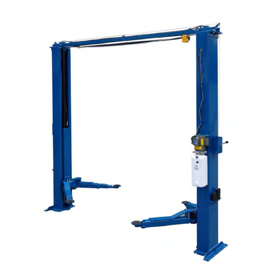
- Page 3 11,000 IRECT RIVE LEAR LOOR SYMMETRIC Features: TP 11 KAC-D 3 UNIQUE TRIPLE Direct Drive TELESCOPING Clear Floor Asymmetric ASYMMETRIC ARMS Lift Dual cylinder direct pull lifting. No chains or roller bearings to wear out Single piece column. Continuous rolled steel column.
- Page 4 TUXEDO DISTRIBUTORS LIMITED WARRANTY Structural Warranty: The following parts and structural components carry a five year warranty: Columns Top Rail Beam Uprights Arms Swivel Pins Legs Carriages Tracks Overhead Beam Cross Rails Limited One-Year Warranty: Tuxedo Distributors, LLC (“Tuxedo”) offers a limited one-year warranty to the original purchaser of Tuxedo lifts and Wheel Service in the United States and Canada.
-
Page 5: Table Of Contents
CONTENTS Safety Information 1.1 Note, Caution and Warning 1.2 Important Information 1.3 Safety Instructions Technical Manual 2.1 Product Description 2.2 Technical Data 2.3 Hydraulic Scheme Operation Manual 3.1 Caution and Warning Label 3.2 Operation Instructions 3.3 Emergency Operation Instruction 3.4 Maintenance Instructions Parts List Troubleshooting Guide -3 -... -
Page 6: Safety Information
1. Safety Information 1.1 Note, Caution and Warning This document uses the following terms—Note, Caution and Warning – to alert you to special instructions, tips, or hazards for a given procedure. Please familiarize yourself with the terms described below. Indicates important information that requires special attention, such as a procedure for a specific vehicle, or tips on operating the equipment. -
Page 7: Safety Instructions
1.3 Safety Instructions 1. Do not raise a vehicle on the lift until the installation is completed as described in this manual. Technicians should be trained to use and care for the lift by familiarizing themselves with the publications listed above. The lift should never be operated by an untrained person. 3. - Page 8 Disclaimers The information contained in this manual was considered accurate at the time of printing and is subject to change without notification. Any corrections should be directed to KERNEL -6 - V1.0...
-
Page 9: Technical Manual
2. Technical Manual 2.1Product Description The TP11KAC-D3 lift is a surface mounted, frame contact lift incorporating the latest safety technologies. Designed and manufactured for a lifting capacity of 11,000 lb, it is fully capable for lifting vehicles, vans and trucks and safely holding them in an elevated position. -
Page 10: Hydraulic Scheme
Figure 1 – Front View Specs & Top View Specs 2.3 Hydraulic Scheme Oil Tank Mesh 3. Gear Pump Power Unit Overflow Valve 6. One-way Valve Cylinder Hand Release Valve Hydraulic Pump 2.2KW, 2850 rpm Setting Pressure 20 Mpa Flow rate for the Pump 2.1 ml/round -8 - V1.0... -
Page 11: Operation Manual
3. Operation Manual Be sure to read and familiarize yourself with the Safety Instructions at the beginning of manual. Failure to follow Safety Instructions may result in property damage, personal injury death. 3.1 Caution and Warning Label V1.0 -9 -... -
Page 12: Operation Instructions
3.2 Operating Instructions Be sure to read and familiarize yourself with the Safety Instructions at the beginning of this manual. Failure to follow Safety Instructions may result in proper damage, personal injury or death. To avoid personal injury and/or property damage, permit only trained personnel to operate lift. - Page 13 DO NOT go under vehicle if all four adapters are not in secure contact at vehicle manufacture’s recommended lift point. g. Repeat complete spotting, loading and raising procedures if required. h. Push the GROUND button to lower the vehicle to the locking position if locking latches are not engaged.
-
Page 14: Emergency Operation Instruction
by qualified lift service personnel. 3.3 Emergency Operation If meet power failure during while the lift is using, follow the instructions to lower the lift. a. Loosen the release bolt; b. Loosen the lowering bolt 3.4 Maintenance Instructions Contact your service provider for instruction before starting up if you are not completely familiar with automotive lift maintenance procedures. - Page 15 Every Month Check equalizer cable tension. Lubricate locking latch shafts. Push latch handle several times for oil to penetrate joints. Lubricate the four inside corners of the legs with heavy duty bearing grease. With lift lowered check the hydraulic fluid level. If necessary add oil as described in the Installation Instruction section of this manual Check carriage latch synching: Latches should click at the same time.
-
Page 16: Parts List
4. Parts List 12-1 -14- V1.0... - Page 17 ITEM DESCRIPTION Spindle Spindle Swing arms Hydraulic cylinder Elbow fitting Haxangular bolt Gear Swing arms(Left) 12-1 Swing arms(Right) Self-lock nut Flat washer Salver jointing Rubber washer Bolt Flex arm Baffle ring Sheath Elbow fitting Flat washer Washer Pulley Cross beam parts Haxangular bolt Haxangular bolt Flat washer...
- Page 18 Air tube Column jointings Sheath Hose T-fitting Hose Hose Carriage Rubber block Retropack jointing Self-lock nut Flat washer Baffle ring Flat washer Roof Spring Pull pole Gear Rack spindle Spring Self-lock nut Flat washer Steel cable Flex arm Haxangular bolt Adjust washer Upset bolt Elbow fitting...
-
Page 19: Troubleshooting Guide
5. Troubleshooting Guide Problem Cause Solution 1. Blown fuse or circuit breaker Replace blown fuse or reset circuit 2. Incorrect voltage to motor breaker. 3. Bad wiring connections. Supply correct voltage to motor. 4. Motor up switch burned out. Motor does not run. Repair and insulate all connections. - Page 20 IMPORTANT POWER UNIT PRIMING PROCEDURE THE PROBLEM: Power unit runs fine but will not pump any fluid. Step 1 – Locate the check valve, the flush plug to the left of the lowering valve. (See drawing below.) Step 2 – Using an Allen wrench and shop towel – with shop towel in place to catch fluid –...
Need help?
Do you have a question about the TP11KAC-D3 and is the answer not in the manual?
Questions and answers