Table of Contents
Advertisement
Quality certified according ISO 9001
Test Interface
E1691
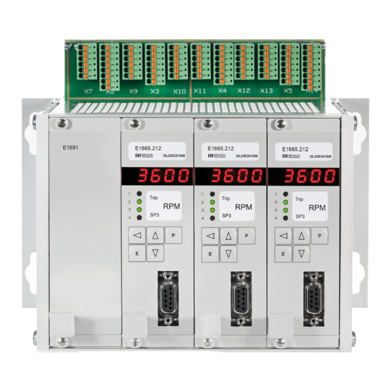
Figure 1: E16x442 System Front View
\BETRANL\E16x442e
Original Manual
Protection-System E16x442
Overspeed Protection
Voters for external Trip Release Conditions
IEC61508;SIL2 and API670 compliant
Monitor A
Monitor A
E1665
SIL2/IEC61508
1
Trip
2
RPM
3
SP3
4
E
I E16x442 Rev: 00
of
with
and
Monitor B
Monitor B
E1665
SIL2/IEC61508
1
Trip
2
RPM
3
SP3
4
P
E
D 71334 Waiblingen-Hegnach
Esslinger Str. 26
Tel.:
+49 (0)7151/956230
Fax:
+49 (0)7151/956250
E-Mail:
info@braun-tacho.de
Internet: www.braun-tacho.de
Monitor C
Monitor C
E1665
SIL2/IEC61508
1
Trip
2
RPM
3
SP3
4
P
P
E
26.11.2014
Page 1 of 73
Advertisement
Table of Contents
Troubleshooting

Summary of Contents for Braun E16x442
- Page 1 Test Interface Monitor A Monitor A Monitor B Monitor B Monitor C Monitor C E1691 E1665 E1665 E1665 SIL2/IEC61508 SIL2/IEC61508 SIL2/IEC61508 Trip Trip Trip Figure 1: E16x442 System Front View I E16x442 Rev: 00 26.11.2014 Page 1 of 73 \BETRANL\E16x442e...
-
Page 2: Table Of Contents
List of Figures ......................4 1.2. List of Abbreviations ....................5 1.3. System Applications and Explanation ..............7 1.4. Key Features of System E16x442 ................7 1.5. Ordering Key for Systems E16x442.abc ..............8 1.6. Safety Data........................9 1.6.1. Safety Data IEC61508; SIL2 ..................9 1.7. - Page 3 3.9. Dimensions of system E16E442 ................29 3.10. Dimensions and Features of E16G442 Enclosure ............ 30 3.11. Weight of E16x442 ....................30 Safety Notes for Installation and Operation ............31 4.1. Safety Notes for Installation ..................31 4.1.1. General Instructions ....................31 4.1.2.
-
Page 4: General Informations
General Informations 1.1. List of Figures Figure 1: E16x442 System Front View Figure 2: E16x442 System Structure Diagram 1 of 2 Figure 3: E16x442 System Structure Diagram 2 of 2 Figure 4: E16x442 System Wiring Diagram 1 of 3 Figure 5:... -
Page 5: List Of Abbreviations
Width unit Triple Modular Redundant Tproof Proof Test Interval UL/cUL Acc. US Underwriter Laboratories resp. Canadian Underwriter Laboratories standards Volt direct current Volt peak-to-peak resp. respective to be continued on next page I E16x442 Rev: 00 Page 5 of 73... - Page 6 Abbreviation Meaning 1oo2 1 out of 2 voting logic 1oo3 1 out of 3 voting logic 2oo2 2 out of 2 voting logic 2oo3 2 out of 3 voting logic I E16x442 Rev: 00 Page 6 of 73...
-
Page 7: System Applications And Explanation
SIL2/ IEC61508 and/or API 670 versus Overspeed and other Critical Con- ditions. The E16x442 system incorporates one Test interface type E1691 and three Monitors (chan- nels) A, B and C of type E1665 for the evaluation of speed signals and external trip signals. -
Page 8: Ordering Key For Systems E16X442.Abc
Additional features of the E16x442-System: Remote test of solenoid valve block by test signals from DCS possible Display in each module for measured values and diagnostics Alarm outputs via opto-relays to DCS Free extra alarm from each monitor ... -
Page 9: Safety Data
Trip-Line I, II, III. The response of the 2oo3 solenoid valve block must be checked by the PLC resp. the operator. Note: Test of two or three trip-lines at the same time will release trip of the machine. I E16x442 Rev: 00 Page 9 of 73... -
Page 10: System Structure And I/Os
The Monitors and the Test Interface are connected via a backplane. The backplane does not hold any active components. 2.1.3. System Design The system is available as 19-Inch Rack File, 3HE 84TE (E16E442) or for surface mounting (E16A442) or as NEMA4 version (E16G442). I E16x442 Rev: 00 Page 10 of 73... -
Page 11: System Structure Diagrams
2.2.3 Speed Signals see 2.2.1 Direction Signals = terminal blocks see 2.2.2 Sensor Rev. 00 / 02.2012 Pole Wheel Figure 2: E16x442 System Structure Diagram 1 of 2 I E16x442 Rev: 00 Page 11 of 73... -
Page 12: Figure 3: E16X442 System Structure Diagram 2 Of 2
Soft- Soft- Soft- 2oo3 Signals Voter 6 ware- ware- ware- Voter 6 altern. Voter Voter Voter n > SPV6 Rev. 00 / 02.2012 Figure 3: E16x442 System Structure Diagram 2 of 2 I E16x442 Rev: 00 Page 12 of 73... -
Page 13: System Wiring Diagrams
3.X1, 9.X1, 3.X15 of Power Supply) Speed Sensor Signal Repeater Outputs see 2.3.3 Connection of sensors see next pages Rev. 02 / 06.2013 Figure 4: E16x442 System Wiring Diagram 1 of 3 I E16x442 Rev: 00 Page 13 of 73... -
Page 14: Figure 5: E16X442 System Wiring Diagram 2 Of
(not with versions E16x442.0xx) E16-System Diagram 1 Signal Inputs Voter 2 through 6 only with systems E16x442.x21 see 2.2.11 Rev. 00 / 09.2012 Figure 5: E16x442 System Wiring Diagram 2 of 3 I E16x442 Rev: 00 Page 14 of 73... -
Page 15: Connection Of Sensors To The Speed Signal Inputs
Connection of Sensors to the Speed Signal Inputs Pin Nos. of BRAUN Sensors A5S... Lead colors of BRAUN cables Terminals Marks for BRAUN cable leads. Mark D only with sensors equipped with direction detection Monitor Cable screen must be connected to screen bar ! brown + Sensor Supply 1.X3... -
Page 16: Position Of Terminal Blocks With Version E16E442
2.1.7. Position of Terminal Blocks with Version E16E442 Figure 7: Position of terminal blocks with version E16E442 I E16x442 Rev: 00 Page 16 of 73... -
Page 17: Position Of Terminal Blocks With Version E16A442
2.1.8. Position of Terminal Blocks with version E16A442 Figure 8: Position of terminal blocks with version E16A442 (shown is version E16A446) I E16x442 Rev: 00 Page 17 of 73... -
Page 18: Inputs Of The System
The input “Reset of Alarms” is rated SIL2/IEC61508 provided that the signal source is rated SIL2/IEC61508. Technical Data of input see 3.1.3. 2.2.4. This chapter is left blank intentionally 2.2.5. This chapter is left blank intentionally I E16x442 Rev: 00 Page 18 of 73... -
Page 19: Inputs Test I, Test Ii, Test Iii
The inputs “Voter 2…6” are rated SIL2/IEC61508 provided that the signal source is rated SIL2/IEC61508. Technical Data of inputs for Voter 2 … 6 see 3.1.3. Note: Systems E16x442.x1x do not have inputs for Voters 2 … 6 . I E16x442 Rev: 00 Page 19 of 73... -
Page 20: Outputs Of The System
Each Monitor has a free adjustable speed alarm output SP3. Configuration of SP3 in steps P05.xx of E1665. The outputs “Speed Alarm SP3” are rated SIL2/IEC61508. Technical Data of outputs see 3.2.3. I E16x442 Rev: 00 Page 20 of 73... -
Page 21: Analog Outputs For Measured Speed (Option)
The (optional) analog outputs have a range of 0/4 .. 20 mamps. Configuration of the analog output in steps P08.xx of E1665. The analog outputs of versions E16x442.1xx are rated SIL2/IEC61508. The analog outputs of Monitors E16x442.2xx are rated SIL2/IEC61508. -
Page 22: Trip Status Of Monitors
Output low: trip Note: The outputs have a delay of approx. 10 seconds versus the trip of the monitor. The Outputs "Trip Status of Monitor" are rated SIL2/IEC61508. Technical Data of output see 3.2.4 I E16x442 Rev: 00 Page 22 of 73... -
Page 23: Power Supply
The RS232 Interface in conjunction with the Interface-Software IS-RS232-E16-L2 (available for End Users) serves to upload parameter settings from Monitors as *.brv files to download parameter settings from *.brv files to spare part Monitors Note: Parameter settings cannot be changed. I E16x442 Rev: 00 Page 23 of 73... -
Page 24: Technical Specifications
Trigger Hysteresis : 0.07 to 2.5 Vpp Impedance : approx. 47 kohms Sensor Supply: (only with versions E16x442.xx2): approx. 24 volts, maximum 120 mamps Inputs are free floating. The sensor inputs have the same common, but are free floating versus other potentials. -
Page 25: Technical Data Of Outputs
Maximum output current : 50 milliamps Outputs are short-circuit proof. Note: In case of short circuit the output is latched to tri state until power supply of the monitor has been switched off and on. I E16x442 Rev: 00 Page 25 of 73... -
Page 26: Technical Data Of Trip-Lines Iv, V, Vi
For inductive type loads, external spark extinguishing means must be provided. Total response time (trip relays de-energize to trip) from trip event until trip circuits are in trip condition : < 15 milliseconds. I E16x442 Rev: 00 Page 26 of 73... -
Page 27: Technical Data Of Power Supply
Maximum AWG according to UL/CUL: 16 3.7. Conformity to Standards 2006/42/EU SIL2/IEC61508, DIN EN ISO 13849-1:2008 Cat 3 PL e, API 670, API 672 2006/95/EU, EN 61010-1, 2004/108/EU, EN 61000-6-2, EN 61000-6-4, IEC 611311-2 I E16x442 Rev: 00 Page 27 of 73... -
Page 28: Dimensions Of System E16A442
(incl. Profibus plug with 35° cable outlet) wiring pluggable premounted screws or terminal bolts with nuts blocks side view wiring all dimensions in mm Drawing not to scale Figure 9: Dimensions of System E16A442 I E16x442 Rev: 00 Page 28 of 73... -
Page 29: Dimensions Of System E16E442
Ø 6 mm wiring from rear side connectors top view (incl. mounting lugs) mounting holes ffnungen all dimensions in mm Drawing not to scale Figure 10: Dimensions of System E16E442 I E16x442 Rev: 00 Page 29 of 73... -
Page 30: Dimensions And Features Of E16G442 Enclosure
Glazed Window with size 360 by 410 mm Material: Fiberglass reinforced plastic Figure 11: Dimensions of E16G442 Enclosure 3.11. Weight of E16x442 E16A442 : 3,0 kg E16E442 : 3,7 kg E16G442: 13,0 kg I E16x442 Rev: 00 Page 30 of 73... -
Page 31: Safety Notes For Installation And Operation
This includes checking of the correct speed display and of the trip release due to a real over- speed condition. If voter inputs are used the correct trip release due to external trip condition must be verified. The parameter settings must be documented and protected against unauthorized changes. I E16x442 Rev: 00 Page 31 of 73... -
Page 32: Description Of Monitor E1665
FC-3.1 : Trip-Line I is tested (Relay I to Trip-Condition) FC-3.2 : Trip-Line II is tested (Relay II to Trip-Condition) FC-3.4 : Trip-Line III is tested (Relay III to Trip-Condition) SELF : Monitor self-test I E16x442 Rev: 00 Page 32 of 73... -
Page 33: Values Accessible During Normal Operation
Reset of latched (and not persistent) alarms, if enabled with key together: Toggle between Standard-Display Mode and Special Display Mode 1 with key together: Toggle between Standard-Display Mode and Special Display Mode 2 I E16x442 Rev: 00 Page 33 of 73... -
Page 34: Special Display Mode 1
P00.02). 5.1.8. Data Interface 9pole Sub-D for PROFIBUS and RS232. Notes: - RS232-Data interface only available for systems with serial nos. exceeding 193850. - For RS232, adapter L3D02 must be used I E16x442 Rev: 00 Page 34 of 73... -
Page 35: Functions Of Monitor 1667
SELF. Selftest of the monitors are inhibited versus each other. The Selftest routine includes CPU RAM-Test CPU EEPROM-Test CPU Command-Test CPU Register-Test Voter Signal-input-Test If the Selftest detects a malfunction, the monitor is set to trip-status. I E16x442 Rev: 00 Page 35 of 73... -
Page 36: Description Of Test Interface E1691
Minimum one Monitor detects a failed speed signal Minimum one Monitor has a malfunction Malfunction of Test Interface The frontside LED is steady on if the power supply of the Test Interface is ok. I E16x442 Rev: 00 Page 36 of 73... -
Page 37: Programming Of The Monitors
Group Step-No. Parameter Value Toggle Toggle Toggle with with with key(s) : Enter : Cancel Enter : new, changed value is valid Cancel : original value still valid Move active digit with I E16x442 Rev: 00 Page 37 of 73... -
Page 38: Programming Of The Modules Via Rs232-Interface
7.2. Programming of the Modules via RS232-Interface adapter L3D02 with cable L3D03 by BRAUN Note: - Adapter L3D02 has male connectors on both sides. - Cable L3D03 has female connectors to L3D02 and to PC. customized cable with connections PC (female connector) to E16 (male connector):... -
Page 39: Parameters Of Monitor E1665
0: no, de-energize / 1: yes, de-energize / 2: no, energize / 3: yes, energize 00001 Setpoint SP1B in RPM 0 Setpoint SP1var : 0: not active / 1: active Continued on next page I E16x442 Rev: 00 Page 39 of 73... - Page 40 0 Truth Time until Trip: 0 ... 11 (see table) 0 Trip latched: 0: no / 1: yes 0 Delay of Antivalence Alarm: 0 ... 9 (see table) 00110 Value for setpoint SPV1 Continued on next page I E16x442 Rev: 00 Page 40 of 73...
- Page 41 0 Truth Time until Trip: 0 ... 11 (see table) 0 Trip latched: 0: no / 1: yes 0 Delay of Antivalence Alarm: 0 ... 9 (see table) 00160 Value for setpoint SPV6 Continued on next page I E16x442 Rev: 00 Page 41 of 73...
- Page 42 0 Reserved for future application 0 Reserved for future application 0 Reserved for future application 0 Reserved for future application 00000 Reserved for future application P17.xx Data Interface P17.00 016 PROFIBUS-Interface Device no. I E16x442 Rev: 00 Page 42 of 73...
-
Page 43: Description Of Parameters And Their Settings Of Monitor E1665
1 : Parameters unlocked, change of parameter values possible P00.03 Setting Frontside Reset of Alarms 0 : Frontside reset of alarms not possible Range: 0 .. 1 1 : Frontside reset of alarms possible with keys I E16x442 Rev: 00 Page 43 of 73... - Page 44 Lower Limit of the Speed ue is given as 0 both for the display and the alarms. The lower limit of the Range speed range is entered in units of RPM. Range as defined in P01.02 I E16x442 Rev: 00 Page 44 of 73...
- Page 45 No of acceleration measure- More measurements included will improve the stability of the calculated set- ments included in calculation point SP1var, but also result in a delayed update rate. of SP1var Range: 1 .. 5 I E16x442 Rev: 00 Page 45 of 73...
- Page 46 7 : Eddy sensor voltage level and current drain (see Note 2) Note 1: The voltage level check is only possible with Braun-sensor type A5S..In this instance even at stand still a defective sensor or supply cable can be detected.
- Page 47 2 : Trip and Alarm latched, starter plausibility check on 3 : Trip and Alarm, till rectified / starter plausibility check off 4 : Trip and Alarm latched / starter plausibility check off I E16x442 Rev: 00 Page 47 of 73...
- Page 48 Monitor A is tested for overspeed, at the same time the signal from sensor B drops out. Monitor B reports an error, but continues to evaluate the signals from sensors A and C. I E16x442 Rev: 00 Page 48 of 73...
- Page 49 Range: 0 .. 2 1 : yes, in this case all occurring event are shown in the display as com- binations 2 : yes, in this case only the first occurring event is displayed I E16x442 Rev: 00 Page 49 of 73...
- Page 50 The numerical value for the setpoint is set in terms of RPM. SP1B is always valid as long as the input „SP1B valid" is true. Overspeed Setpoint SP1B Range: 00001 .. 99999 I E16x442 Rev: 00 Page 50 of 73...
-
Page 51: Figure 13: Sp1 As A Variable Of The Acceleration
120 RPM/sec 3180 RPM 60 RPM/sec 3210 RPM 0 RPM/sec 3240 RPM See also graph below Value SP1var SP1A SP1B Figure 13: SP1 as a variable of the acceleration acceleration dN/dt dN/dt max I E16x442 Rev: 00 Page 51 of 73... - Page 52 With 5% Hysteresis and a setpoint of 100 RPM a Lowspeed alarm is issued once speed drops below 100 RPM and ceases once speed exceeds 105 RPM. P04.02 Fix value = 0, do not change I E16x442 Rev: 00 Page 52 of 73...
- Page 53 > SP3 2 : LED3 (green) on at n > SP3 and LED4 blinking at reverse rotation 3 : LED4 (red) on at n > SP3 but LED4 blinking at reverse rotation I E16x442 Rev: 00 Page 53 of 73...
- Page 54 Range: 0.0 to 2.5 The hysteresis must be larger than the possible noise on the signal line in order to achieve a proper speed measurement. Note: with setting 0.0 hysteresis is approx 70 millivolts I E16x442 Rev: 00 Page 54 of 73...
- Page 55 Relay State for status forward 0 : Relay de-energized at status forward motion motion 1 : Relay energized at status forward motion Range: 0 .. 1 P07.04 Reserved for future application. Fix value 0 I E16x442 Rev: 00 Page 55 of 73...
- Page 56 If a fault is detected, the analog output circuit is switched to high ohmic state, event code E.3.0.2.0 (at external fault) or E.3.0.2.1 (at internal fault = monitor must be replaced) is displayed and Monitor Warning Alarm signal- ized. I E16x442 Rev: 00 Page 56 of 73...
- Page 57 Parameter Group P09.xx of Monitor E1665 Reserved for future application Parameter No. Description of Parameters and their Settings Meaning of Parameter Setting Range of Parameter P09.00 Reserved for future application I E16x442 Rev: 00 Page 57 of 73...
- Page 58 6.400 sec P10.04 Setting Trip by Voter 1 latched 0 : trip by voter 1 is not latched Range: 0 .. 1 1 : trip by voter 1 is latched until reset I E16x442 Rev: 00 Page 58 of 73...
- Page 59 Depending on setting of P10.00, SPV1 controls the activity of voter 1 or con- Setpoint SPV1 trols directly the output LO1. Range: 00001 .. 99999 [RPM] SPV1 is set in terms of RPM. I E16x442 Rev: 00 Page 59 of 73...
- Page 60 6.400 sec P11.04 Setting Trip by Voter 2 latched 0 : trip by voter 2 is not latched Range: 0 .. 1 1 : trip by voter 2 is latched until reset I E16x442 Rev: 00 Page 60 of 73...
- Page 61 Depending on setting of P11.00, SPV2 controls the activity of voter 2 or con- Setpoint SPV2 trols directly the output LO2. Range: 00001 .. 99999 [RPM] SPV2 is set in terms of RPM. I E16x442 Rev: 00 Page 61 of 73...
- Page 62 6.280 sec 6.400 sec P12.04 Setting Trip by Voter3 latched 0 : trip by voter 3 is not latched Range: 0 .. 1 1 : trip by voter 3 is latched until reset I E16x442 Rev: 00 Page 62 of 73...
- Page 63 Depending on setting of P12.00, SPV3 controls the activity of voter 3 or con- Setpoint SPV3 trols directly the output LO3. Range: 00001 .. 99999 [RPM] SPV3 is set in terms of RPM. I E16x442 Rev: 00 Page 63 of 73...
- Page 64 6.400 sec P13.04 Setting Trip by Voter 4 latched 0 : trip by voter 4 is not latched Range: 0 .. 1 1 : trip by voter 4 is latched until reset I E16x442 Rev: 00 Page 64 of 73...
- Page 65 Depending on setting of P13.00, SPV4 controls the activity of voter 4 or con- Setpoint SPV4 trols directly the output LO4. Range: 00001 .. 99999 [RPM] SPV4 is set in terms of RPM. I E16x442 Rev: 00 Page 65 of 73...
- Page 66 6.400 sec P14.04 Setting Trip by Voter 5 latched 0 : trip by voter 5 is not latched Range: 0 .. 1 1 : trip by voter 5 is latched until reset I E16x442 Rev: 00 Page 66 of 73...
- Page 67 Depending on setting of P14.00, SPV5 controls the activity of voter 5 or con- Setpoint SPV5 trols directly the output LO5. Range: 00001 .. 99999 [RPM] SPV5 is set in terms of RPM. I E16x442 Rev: 00 Page 67 of 73...
- Page 68 6.400 sec P15.04 Setting Trip by Voter 6 latched 0 : trip by voter 6 is not latched Range: 0 .. 1 1 : trip by voter 6 is latched until reset I E16x442 Rev: 00 Page 68 of 73...
- Page 69 Depending on setting of P15.00, SPV6 controls the activity of voter 6 or con- Setpoint SPV6 trols directly the output LO6. Range: 00001 .. 99999 [RPM] SPV6 is set in terms of RPM. I E16x442 Rev: 00 Page 69 of 73...
- Page 70 Description of Parameters and their Settings Meaning of Parameter Setting Range of Parameter All members of the PROFIBUS-Communication must have different device P17.00 nos. Device No for PROFIBUS Range: 001 .. 125 I E16x442 Rev: 00 Page 70 of 73...
-
Page 71: This Chapter Is Left Blank Intentionally
Starter Input is active at speed > 50% of SP1A (only if P02.06 = 1 or 2) E.3.0.2.0 External Analog output error ( 'no load' or fault of connected device ) E.3.0.2.1 Internal Analog output error (fault on monitor board) -E1- Wrong code figure in step P00.00 I E16x442 Rev: 00 Page 71 of 73... -
Page 72: Troubleshooting If Display Of Monitor Reads E.0.4.X.x
4.3.0.0.5 : Voter 3, inputs 1 und 3 active, input 2 not active. While key is pressed, the input status latched at error will be shown, else the current in- put status. Switch the input status of voter 1 to 6 with key I E16x442 Rev: 00 Page 72 of 73... -
Page 73: Revision Notes
Revision notes Date Rev. Modification 26.11.2014 First release I E16x442 Rev: 00 Page 73 of 73...