
Summary of Contents for SmarTrunk Systems ST-9116C
- Page 1 UHF FM DIGITAL REPEATER ST-9116C (400Mhz ~ 470Mhz) SERVICE MANUAL SmarTrunk Systems, INC. ST-9116C SM R1.1...
-
Page 2: Table Of Contents
Contents SPECIFICATIONS: ........................5 ST-9116 EXPLODED VIEW ...................... 6 ST-9116C SIMPLIFIED DIAGRAM ................... 7 4. - ST-9116C RF DESCRIPTION ....................8 4.1. CIRCUIT CONFIGURATION ..................... 8 4.2. RECEIVER SYSTEM ......................... 8 4.2.1. FRONT-END RF RECEIVER ...................... 8 4.2.2. ANALOG AUDIO PROCESSING ....................8 4.2.3. - Page 3 ANALOG ROAMING GAIN ....................32 5.7.5. VOCODER OUT GAIN ......................32 5.7.6. VOCODER IN GAIN....................... 33 COMPLIMENTARY USER ALIGNMENT ................. 34 6.1. TEMPERATURE CONTROL: ....................34 6.2. FAN CONTROL: ........................34 ST-9116C MAIN BOARD SCHEMATIC .................. 37 ST-9116C SM R 1.1 SMARTRUNK SYSTEMS, INC.
- Page 4 ST-9116 FRONT BOARD SCHEMATIC ....................38 COMPONENT LOCATOR ......................39 9.1. ST-9116 COMPONENT LOCATOR (TOP LAYER) ................39 9.2. ST-9116C COMPONENT LOCATOR (BOTTOM LAYER) ..............40 MAIN PCB LAYOUT ........................41 10.1. MAIN PCB – TOP LAYER ....................... 41 10.2.
-
Page 5: Specifications
1. SPECIFICATIONS: SPECIFICATION Frequency Range 400 TO 470 [Mhz] Channels Digital Protocol Digital FMDA / TDMA / ANALOG / HIBRID IP Interface TCP/UDP IEEE 802.3 Power 12 ~ 15 Vdc Dimensions 90 (h) x 482.6 (w) x 173.1 (d) [mm] ; (3.5(h) x 19(w) x 5.65 (d)) (in) Target Weight 2.4Kg (5.2lbs) Temperature range... -
Page 6: St-9116 Exploded View
ST-9116 EXPLODED VIEW... -
Page 7: St-9116C Simplified Diagram
3. ST-9116C SIMPLIFIED DIAGRAM TX CTRL [Q9 Q18] Buffer Power Detection Final AMP Driver TX Radio CLOCK [Y1] POWER CTRL [U9] Audio Processor CLOCK TX VOCODER TX Modem [Y3] [U21] [U20] DISPLAY FLASH MEMORY [U30] [J8] RAM MEMORY [U23] Main Processor... -
Page 8: St-9116C Rf Description
4. - ST-9116C RF DESCRIPTION Band pass control Filter CTRL 4.1. CIRCUIT CONFIGURATION [U10] The receiver is a single receiver with FILTER AMPLIFIER FILTER Radio D12/D13 D9/D11 built DSP fully integrated. Gain control Incoming signals from the antenna, after passing through LPF filter, are... -
Page 9: Virtual Squelch Circuit
PWM incoming audio (PCM) is 4.2.6. ANALOG AUDIBLE SIGNALING delivered to the PWM filter to be integrated then it is fed to the amplifier. DTMF signals, MDC1200 and tone signals are processed and decoded ST-9116C SM R 1.1 SMARTRUNK SYSTEMS, INC. -
Page 10: Digital Audio Processing
(U37) where the analog signal is Figure 4: Analog Modulation path sampled with AdPCM format, filtered processed delivered to the PWM filter then to the audio amplifier (U36). AdPCM audio frames are also sent to the IP ST-9116C SM R 1.1 SMARTRUNK SYSTEMS, INC. -
Page 11: Analog Repeater Loop
(low frequencies) is fed to the VC-TXCO. The balance of Figure 5: Analog Repeater loop path that information is controlled by the TX audio processor, depending on the modulation type required. ST-9116C SM R 1.1 SMARTRUNK SYSTEMS, INC. -
Page 12: Repeater Digital Tx Audio
The output of the modem is fed into spurious radiation before delivery the TX radio chip and a portion of to the antenna that modulation (low frequencies) is fed to the VC-TXCO. The balance of ST-9116C SM R 1.1 SMARTRUNK SYSTEMS, INC. -
Page 13: Automatic Transmit Power Control
DC bias input of the hybrid module. Evenly when power level is adjusted by software on three levels (Hi, Med, Lo) the power value can be adjusted to any desired value between zero and 50Watts by the alignment software. ST-9116C SM R 1.1 SMARTRUNK SYSTEMS, INC. -
Page 14: St-9116 Alignment
Authorized adjustments performed Smartrunk service technicians afterwards. Do not attempt to realign circuits make perform only a single step unless it complete performance checks to ST-9116C SM R 1.1 SMARTRUNK SYSTEMS, INC. -
Page 15: Required Test Equipment
Alignment Preparation & repeater on before continue with Precautions this alignment procedure. A 50-Ohm RF Dummy Load and in- line wattmeter must be connected to the TX antenna jack in all ST-9116C SM R 1.1 SMARTRUNK SYSTEMS, INC. -
Page 16: Main Repeater Alignment
Setup the test equipment as shown loaded. for repeater alignment; apply 13.8V DC power to the repeater. Once the repeater is connected, a new screen pops up showing all ST-9116C SM R 1.1 SMARTRUNK SYSTEMS, INC. -
Page 17: Tx Clock Alignment
ST-9116 has three power levels to be selected for each channel. High, Figure 11: TX clock Alignment medium and low power level can be aligned repeater usage requirement. Actual alignment value will be displayed on alignment slider. ST-9116C SM R 1.1 SMARTRUNK SYSTEMS, INC. -
Page 18: High Power Level Alignment
[Start], value manually at the time you otherwise the alignment should be check the real transmit power on not correct. the wattmeter connected to the repeater as recommended on TX alignment diagram. ST-9116C SM R 1.1 SMARTRUNK SYSTEMS, INC. -
Page 19: Mid Power Level Alignment
5.6.3. ANALOG MAXIMUM DEVIATION [Start]. You will be asked to confirm FOR NARROW BAND the factory default alignment, and then if you confirm it, original values from factory will be loaded into current alignment settings ST-9116C SM R 1.1 SMARTRUNK SYSTEMS, INC. -
Page 20: Analog Maximum Deviation For Wide Band
If you want to retrieve factory KHz deviation for Ultra Narrowband default, press [Factory] instead of channels (6.25Khz channel [Start]. You will be asked to confirm bandwidth). the factory default alignment, and then if you confirm it, original ST-9116C SM R 1.1 SMARTRUNK SYSTEMS, INC. -
Page 21: Tdma Data Modulation Alignment
[Finish] to store the reach the desired signaling level for value on repeater memory. narrow band operation. repeater will generate a 1000Hz alignment ST-9116C SM R 1.1 SMARTRUNK SYSTEMS, INC. -
Page 22: Smartrunk Ii Dev Alignment (Wide Band)
Figure 21: SmarTrunk II Level Alignment Screen for wide band signals Actual alignment value will be Figure 22: EIA Tones Level Alignment Screen displayed on alignment slider. Press [Start] then move the slider to reach the desired value at the time ST-9116C SM R 1.1 SMARTRUNK SYSTEMS, INC. -
Page 23: Eia Tones Level Alignment (Wide Band)
Tones EIA Dev (25.0Khz) alignment option form 5.6.11. DTMF SIGNALING LEVEL alignment menu. ALIGNMENT FOR NARROW BAND CHANNELS: DTMF signaling generated by ST- 9116 in Narrow Band Channels must be aligned by selecting DTMF Dev (12.5Khz) ST-9116C SM R 1.1 SMARTRUNK SYSTEMS, INC. -
Page 24: Dtmf Signaling Level Alignment For Wide Band Channels
5.6.12. DTMF SIGNALING LEVEL ALIGNMENT FOR WIDE BAND CHANNELS: ST-9116C SM R 1.1 SMARTRUNK SYSTEMS, INC. -
Page 25: Dcs Signaling Alignment For Narrow Band Channels
If you want to retrieve factory Default value corresponds to 600Hz default, press [Factory] instead of deviation for wide band channels. [Start]. You will be asked to confirm the factory default alignment, and ST-9116C SM R 1.1 SMARTRUNK SYSTEMS, INC. -
Page 26: Ctcss Signaling Alignment For Narrow Band Channels
[Finish] to store the narrow band operation. Repeater value on repeater memory. ST-9116C SM R 1.1 SMARTRUNK SYSTEMS, INC. -
Page 27: Fsk Signaling Alignment For Narrow Band Channels
Figure 30: FSK Modulation Level Alignment Screen for Narrow band Channels Actual alignment value will be displayed on alignment slider. Press [Start] then move the slider to reach the desired value at the time ST-9116C SM R 1.1 SMARTRUNK SYSTEMS, INC. -
Page 28: Rx Clock Alignment
Frequency field of the alignment screen. 5.6.19. RX CLOCK ALIGNMENT: soon desired value To align the RX clock for Repeater, reached, press [Finish] to store the please select: value on repeater memory. Adjust Clock RX ST-9116C SM R 1.1 SMARTRUNK SYSTEMS, INC. - Page 29 This confirmation screen will appears any time you want to realign any parameter to Factory Default. ST-9116C SM R 1.1 SMARTRUNK SYSTEMS, INC.
-
Page 30: Receiver Alignment
Under your risk, if you still prefer to realign the overall modulation gain, Disc. Gain FDMA you must select on Alignment screen. Disc. Gain Analog on Alignment screen. ST-9116C SM R 1.1 SMARTRUNK SYSTEMS, INC. -
Page 31: Tdma Discriminator Gain
Under your risk, if you still prefer to realign the overall modulation gain, you must select Disc. Gain TDMA on Alignment screen. ST-9116C SM R 1.1 SMARTRUNK SYSTEMS, INC. -
Page 32: Analog Roaming Gain
[Start]. You will be asked to confirm into current alignment settings. the factory default alignment, and then if you confirm it, original values from factory will be loaded into current alignment settings. ST-9116C SM R 1.1 SMARTRUNK SYSTEMS, INC. -
Page 33: Vocoder In Gain
[Finish] to store the value on repeater memory. If you want to retrieve factory default, press [Factory] instead of [Start]. You will be asked to confirm the factory default alignment, and ST-9116C SM R 1.1 SMARTRUNK SYSTEMS, INC. -
Page 34: Complimentary User Alignment
Alignment screen. temperature. To align the temperature where the fan start working, please select: Fan On Temp [C] option Alignment screen. Figure 40: Max temperature control ST-9116C SM R 1.1 SMARTRUNK SYSTEMS, INC. - Page 35 [Factory] instead of [Start]. You will be asked to confirm the factory default alignment, and then, if you confirm it, original values from factory will be loaded into current alignment settings. ST-9116C SM R 1.1 SMARTRUNK SYSTEMS, INC.
- Page 36 Notes: ST-9116C SM R 1.1 SMARTRUNK SYSTEMS, INC.
-
Page 37: St-9116C Main Board Schematic
TRANSM ITTER IF COMPONENT IS DIFERENT BETWEEN THE DIFERENT MODELS, THEN Y OU WILL FIND THREE VALUES UNDER THE COMPONENT. TP63 TX8V TX8V BLUE VALUES CORRESPOND TO ST-9116V PINK VALUES CORRESPOND TO ST-9116C & ST-9116D RA60H1317M ANTENNA TEMP 39nH 39nH 39nH 470pF 2 .2... -
Page 38: St-9116 Front Board Schematic
RXLED SW ALPS SW ALPS TP12 SW ALPS SW ALPS TP11 SW ALPS SW ALPS TP10 SW ALPS SW ALPS SmarTrunk Systems, INC. Title DISPLAY ST-9116 FRONT BOARD R1.0 Size Document Number DM-130214-01 Date: Sunday , June 02, 2013 Sheet... -
Page 39: Component Locator
COMPONENT LOCATOR 9.1. ST-9116 COMPONENT LOCATOR (TOP LAYER) ST-9116C SM R 1.1 SMARTRUNK SYSTEMS, INC. -
Page 40: St-9116C Component Locator (Bottom Layer)
9.2. ST-9116C COMPONENT LOCATOR (BOTTOM LAYER) ST-9116C SM R 1.1 SMARTRUNK SYSTEMS, INC. -
Page 41: Main Pcb Layout
MAIN PCB LAYOUT MAIN PCB – TOP LAYER 10.1. ST-9116C SM R 1.1 SMARTRUNK SYSTEMS, INC. -
Page 42: Main Pcb - Bottom Layer
10.2. MAIN PCB – BOTTOM LAYER ST-9116C SM R 1.1 SMARTRUNK SYSTEMS, INC. -
Page 43: Main Pcb - Power Layer
10.3. MAIN PCB – POWER LAYER ST-9116C SM R 1.1 SMARTRUNK SYSTEMS, INC. -
Page 44: Main Pcb - Ground Layer
10.4. MAIN PCB – GROUND LAYER ST-9116C SM R 1.1 SMARTRUNK SYSTEMS, INC. -
Page 45: St-9116 Front Board Component Locator
ST-9116 FRONT BOARD COMPONENT LOCATOR... -
Page 46: St-9116 Front Board Layout
ST-9116 FRONT BOARD LAYOUT ST-9116C SM R 1.1 SMARTRUNK SYSTEMS, INC. -
Page 47: St-9116 Bom
ST-9116 BOM 13.1. ST-9116C MAIN PCB BOM LOCATIO SMARTRUNK PART DESCRIPTION VALUE MAIN PCB REV 2.0C EPL911611A C208 CAP CER 10PF 50V NP0 0402 10pF CK1100AK2A C230 CAP CER 47PF 50V NPO SMD 0402 47pF CK1470AK4A C235 CAP CER 47PF 50V NPO SMD 0402... - Page 48 CAP CER 1000PF 50V 10% X7R 0402 CK1102AK5X C189 CAP CER 1000PF 50V 10% X7R 0402 CK1102AK5X C196 CAP CER 1000PF 50V 10% X7R 0402 CK1102AK5X C197 CAP CER 1000PF 50V 10% X7R 0402 CK1102AK5X ST-9116C SM R 1.1 SMARTRUNK SYSTEMS, INC.
- Page 49 CAP CER 1000PF 50V 10% X7R 0402 CK1102AK5X C353 CAP CER 1000PF 50V 10% X7R 0402 CK1102AK5X C354 CAP CER 1000PF 50V 10% X7R 0402 CK1102AK5X C357 CAP CER 1000PF 50V 10% X7R 0402 CK1102AK5X ST-9116C SM R 1.1 SMARTRUNK SYSTEMS, INC.
- Page 50 CAP CER 0.1UF 16V 10% X7R 0402 100nF CK5104AK5X CAP CER 0.1UF 16V 10% X7R 0402 100nF CK5104AK5X C114 CAP CER 0.1UF 16V 10% X7R 0402 100nF CK5104AK5X C117 CAP CER 0.1UF 16V 10% X7R 0402 100nF CK5104AK5X ST-9116C SM R 1.1 SMARTRUNK SYSTEMS, INC.
- Page 51 CAP CER 0.1UF 16V 10% X7R 0402 100nF CK5104AK5X CAP CER 1UF 16V 10% X5R 0402 CK5105AK7R CAP CER 1UF 16V 10% X5R 0402 CK5105AK7R C173 CAP CER 1UF 16V 10% X5R 0402 CK5105AK7R ST-9116C SM R 1.1 SMARTRUNK SYSTEMS, INC.
- Page 52 CAP CER 10PF 250V 5% NP0 0603 10pF CK9100AD2A CAP CER 100PF 250V 5% 0603 100pF CK9101AD5A CAP CER 100PF 250V 5% 0603 100pF CK9101AD5A CAP CER 100PF 250V 5% 0603 100pF CK9101AD5A ST-9116C SM R 1.1 SMARTRUNK SYSTEMS, INC.
- Page 53 CAP TANT 10UF 20V 20% 1206 10uF CTY201066A C293 CAP TANT 10UF 20V 20% 1206 10uF CTY201066A C296 CAP TANT 10UF 20V 20% 1206 10uF CTY201066A C298 CAP TANT 10UF 20V 20% 1206 10uF CTY201066A ST-9116C SM R 1.1 SMARTRUNK SYSTEMS, INC.
- Page 54 INDUCTOR HI FREQ 33NH 5% 0603 33nH YCMCI3333D INDUCTOR 68NH 150MA 0603 68nH YCMCI6833D INDUCTOR 1UH YCMCI1054D SMT Shielded Power Inductors 18581 YCBAD18581R FERRITE BEAD CHIP BEAD YCBAD18594 'VHF to UHF Wide-Band Low-Noise 2SC5226 TY2SC5226Z ST-9116C SM R 1.1 SMARTRUNK SYSTEMS, INC.
- Page 55 RES 47 OHM 1/16W 5% 0402 SMD RCY044704Z R231 RES 47 OHM 1/16W 5% 0402 SMD RCY044704Z R233 RES 47 OHM 1/16W 5% 0402 SMD RCY044704Z R239 RES 47 OHM 1/16W 5% 0402 SMD RCY044704Z ST-9116C SM R 1.1 SMARTRUNK SYSTEMS, INC.
- Page 56 RCY041024Z RES 1.0K OHM 1/16W 5% 0402 SMD RCY041024Z RES 1.0K OHM 1/16W 5% 0402 SMD RCY041024Z RES 1.0K OHM 1/16W 5% 0402 SMD RCY041024Z RES 1.0K OHM 1/16W 5% 0402 SMD RCY041024Z ST-9116C SM R 1.1 SMARTRUNK SYSTEMS, INC.
- Page 57 RES 10K OHM 1/16W 5% 0402 SMD RCY041034Z R128 RES 10K OHM 1/16W 5% 0402 SMD RCY041034Z R131 RES 10K OHM 1/16W 5% 0402 SMD RCY041034Z R155 RES 10K OHM 1/16W 5% 0402 SMD RCY041034Z ST-9116C SM R 1.1 SMARTRUNK SYSTEMS, INC.
- Page 58 RES 220K OHM 1/16W 5% 0402 SMD 220K RCY042244Z R124 RES 220K OHM 1/16W 5% 0402 SMD 220K RCY042244Z R201 RES 220K OHM 1/16W 5% 0402 SMD 220K RCY042244Z R194 RES 470K OHM 1/16W 5% 0402 SMD 470K RCY044744Z ST-9116C SM R 1.1 SMARTRUNK SYSTEMS, INC.
- Page 59 YNMR6241UT IC REG POS 1.5A 8V PREC DPAK 7808 YNRO7808FP LDO LINEAR REGULATOR 1.8V 300mA RT9167/18PB YNHT07218Z IC REG LDO 3.3V .5A D-PAK LM1117 YNSR001117 IC REG LDO 5.0V .3A SOT23-5 RT9167/50 YNHT07250Z ST-9116C SM R 1.1 SMARTRUNK SYSTEMS, INC.
- Page 60 CRYSTAL (SMD)3.3V 19.2MHz+-0.5ppm TXC19.2M EF0192000Y CRYSTAL 25.000000 MHZ 8PF SMD EFO250000Y CRYSTAL 32.768 KHZ 6PF SMD 32768 EFO327680Y EYDOB12000 CRYSTAL 12MHz SMD 12MHzB 20PF V TYPE JACK(M PIN) GZZZ50062Z V TYPE JACK(M PIN) GZZZ50062Z ST-9116C SM R 1.1 SMARTRUNK SYSTEMS, INC.
-
Page 61: St-9116C Front Panel Assembly Bom
13.2. ST-9116C FRONT PANEL ASSEMBLY BOM ST-9116 FRONT PCB 1.0 BOM ITEM DESCRIPTION NAME VALUE PART # CAP CER 0.1UF 16V 10% X7R 0402 CK5104AK5X CAP CER 10UF 6.3V Y5V 0805 LED GREEN/RED BICOLOR 0606 SMD LTST-C195KGJRKT DISPLAY REPATER_PCB RES 1.0K OHM 1/16W 5% 0402 SMD RCY041024Z RES 1.0K OHM 1/16W 5% 0402 SMD... -
Page 62: External Connections
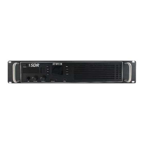
On the front side of the repeater, you will find the following ports and controls: Audio Monitor On-Off Display Control Programmable functions External SD Card Port Monitor Monitor Squelch Volume Port control control ST-9116C SM R 1.1 SMARTRUNK SYSTEMS, INC. -
Page 63: Accessory Port
AUDIO OUTPUT FROM DIGITAL CHANNEL 2 FOR ACCESSORY CONNECTION - 1.6v BIASED - 2VPP EMI2 EXTERNAL MODULATION INPUT 2 - 1KOHM - 1VRMS EAI2 ANALOG INPUT - HI Z - 3.3VMAX - PROTECTED 14.2. USB: USB 2.0 COMPLIANCE ST-9116C SM R 1.1 SMARTRUNK SYSTEMS, INC. -
Page 64: External Mic Connector Pin Out
DO NOT CONNECT 3 DI1 DIGITAL INPUT FOR FUTURE APPLICATION 4 GND GROUND CONNECTION 5 MIC MIC INPUT BIASED 6 PTT PTT INPUT 7 NC DO NOT CONNECT 8 NC DO NOT CONNECT ST-9116C SM R 1.1 SMARTRUNK SYSTEMS, INC. -
Page 65: Sd Card Socket
14.4. SD CARD SOCKET ST-9116C SM R 1.1 SMARTRUNK SYSTEMS, INC. -
Page 66: List Of Figures
CREEN 38: V ..................... 32 IGURE OCODER LIGNMENT CREEN 39: V ......................33 IGURE OCODER LIGNMENT CREEN 40: M ........................34 IGURE AX TEMPERATURE CONTROL 41: F .......................... 35 IGURE AN OPERATION CONTROL ST-9116C SM R 1.1 SMARTRUNK SYSTEMS, INC. - Page 67 Copyright 2014 Printed in Malaysia www.smartrunk.com ST-9116CSM R1.1 Jun-14...
Need help?
Do you have a question about the ST-9116C and is the answer not in the manual?
Questions and answers