Table of Contents
Advertisement
Advertisement
Table of Contents

Subscribe to Our Youtube Channel
Related Manuals for Hycontrol MINIFLEX LR

Summary of Contents for Hycontrol MINIFLEX LR
- Page 1 Rev 0 MINIFLEX LR PROGRAMMABLE LEVEL CONTROLLER INSTALLATION AND OPERATION MANUAL Hycontrol Limited, Larchwood House, Orchard Street, Redditch, Worcestershire, B98 7DP, UK. Tel: +00 44 (0)1527 406800 Fax: +00 44 (0)1527 406810 Email: sales@hycontrol.com Web: www.hycontrol.com...
-
Page 2: Table Of Contents
Fig. 6 Transducer Stand Pipe Transducer Cable Extensions Fig. 7 & 8 Temperature Sensor Fig. 9 SECTION 2 Easy start for Miniflex LR Quick Start Guide Principle of Programming Keypad Definitions 10 - 11 To Enter Programme To Enter the Password... -
Page 3: Introduction
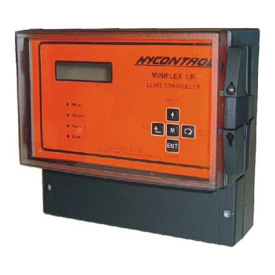
USER MANUAL INTRODUCTION Miniflex LR is a programmable multi-purpose level measurement and flow control instrument. It consists of two elements, a wall mounted transceiver, which has a display and an integral keypad for programming, and a transducer, which must be mounted directly above the surface to be monitored. -
Page 4: Installation
MOUNTING POINT 2 & 3 (REMOVE TERMINAL COVER) ∅5.4 198.0 213.0 ∅ ∅ KNOCKOUTS FOR 1 HOLE 16mm AND 5 HOLES 20mm NOTE: - All dimensions are shown in mm Figure 1: Enclosure dimensional & mounting drawing Ref: MINIFLEX LR MANUAL Rev. 0... - Page 5 SECTION 1 Electrical and Transducer Connections The Miniflex LR has two-part screw terminals; the top part can be removed for ease of connection. It can be powered from either an AC or DC supply. Power Supply Remove the terminal cover to expose the terminals shown below.
- Page 6 13 RS485 Output RS485 - is connected : - Shield to terminal 3 Negative –ve to terminal 4 Positive +ve to terminal 5 Note: - See Page 8 for transducer extension cables. Ref: MINIFLEX LR MANUAL Rev. 0...
-
Page 7: Transducer Mounting 5 Fig
Refer to Page 8 for full details. Transducer cables and temperature compensation cables can be run together but should be separated from power cables by at least 150mm and preferably installed in their own earthed steel conduit. Ref: MINIFLEX LR MANUAL Rev. 0... - Page 8 For differential applications mount both transducers at the same height above the zero datum point. For open channel flow applications the transducer must be mounted upstream of the flume or weir as detailed in BS3680 (usually 3 or 4 times maximum head). Ref: MINIFLEX LR MANUAL Rev. 0...
- Page 9 Using a 4" flanged transducer would require the standpipe length to be no more than 300mm and Pr.4.0 set at 450mm minimum. The inside of the pipe and joint with vessel top must be clean and free of any obstructions, seams or welds. Ref: MINIFLEX LR MANUAL Rev. 0...
-
Page 10: Transducer Cable Extensions 8 Fig. 7
10 11 12 13 14 15 16 17 18 19 20 21 22 23 24 25 DC POWER AC POWER 21.6-30VDC 95/110/230V AC +10%/-10% RS485 ISOLATED 50/60 HZ 12VA TRANSDUCER ANALOG OUTPUT RELAY 1 RELAY 2 RELAY 3 Figure 8: Transducer Wiring for Differential Mode Ref: MINIFLEX LR MANUAL Rev. 0... -
Page 11: Temperature Sensor Fig
POLARITY 34 ref UNIMPORTANT 33 HEX INTERNAL EXTERNAL EARTH EARTH HOUSING: CAST IRON BLACK EPOXY PAINT CLASSIFICATION EEx e II T6/IP 65 PROBE: 316SS TEMPERATURE SENSOR RTS 2B Figure 9 Temperature sensor dimensional drawing Ref: MINIFLEX LR MANUAL Rev. 0... -
Page 12: Easy Start For Miniflex Lr
SECTION 2 EASY START FOR MINIFLEX LR The Miniflex LR system requires programming by the operator to obtain the required measurements and control. To create a basic working system, only the application type and parameters 2.0 to 5.0 need be programmed. To become familiar with the use of the system, it is suggested that the following QUICK START guide is used before the instrument is installed. -
Page 13: To Enter Programme
1 it will change to relay 2 and if pressed again relay 3. NOTE:- The Miniflex LR comes with pre-programmed applications, which can be simply modified SECTION 4 to meet your applications requirements. See for more details. -
Page 14: To Change An Option
8.1 Rly1 Options e.g. (Norm–Energised) Press ENT 8.1.1 Relay 1 Norm - Energised Press to change the option 8.1.2 Relay 1 Norm-DeEnergised Press to change the option again 8.1.3 Relay 1 Temp Alarm Ref: MINIFLEX LR MANUAL Rev. 0... -
Page 15: To Reset
= Reduce speed by 2 from a maximum of 64x to 1x. The initial speed of 1x is set by the rate of change defined in parameter 6.0. = Increase speed by 2. From 1x to a maximum of 64x. Ref: MINIFLEX LR MANUAL Rev. 0... - Page 16 Pr. 8.2 Relay2 Options Pr. 8.3 Relay3 Options Pump Control Pr. 9.1 Pump Sequence Pr. 9.2 Duty Standby Pr. 9.3 Exerciser Pr. 9.4 Tolerance Pr. 9.5 Maintenance Pr. 9.6 Pump Run-on Interval Pr. 9.7 Pump Run-on Time Ref: MINIFLEX LR MANUAL Rev. 0...
-
Page 17: Programming The Instrument
Analogue section go to Pages 31 - 32 Step 7: - Set any miscellaneous conditions Miscellaneous section go to Pages 33 - 34 Step 8: - Exit program mode and return to run mode Go to Section 7 Page 13 Ref: MINIFLEX LR MANUAL Rev. 0... -
Page 18: Distance Measurement Mode
SECTION 3 Pr.1.0 APPLICATION SELECTION GUIDE Miniflex LR can be programmed for Distance measurement, Level measurement, Volume measurement, Pump control, OCM and Differential measurement. Each application selected will allow access to only parameters associated with that application. Distance Measurement Displays a distance measurement; relay set and reset points can be programmed and a relay can be programmed for Loss Of Echo indication. - Page 19 1.0m/min or that the system continually 'tracks' a level lower than the actual level. If it is necessary to change the value, enter the new value in m/min; the suggested range is 0.1 to 10. Ref: MINIFLEX LR MANUAL Rev. 0...
- Page 20 Pr.3.0 Enter cone h in metres. Pr.6.1.3.1 Cone h 6.1.3 VERTICAL CONICAL BOTTOM Pr 6.1.4.1 Sphere h (D = 0.00) Enter sphere h in metres. Pr.3.0 Pr. 6.1.4.1 Sphere h 6.1.4 VERTICAL SPHERICAL BOTTOM. Ref: MINIFLEX LR MANUAL Rev. 0...
- Page 21 % reading. Pr. 6.4 Disp. Format Display Format (D = Contents) Options displayed Description 6.4.1 Display Contents Display contents only 6.4.2 Display Ullage Display ullage only 6.4.3 Display Ullage &Contents Display both ullage and contents Ref: MINIFLEX LR MANUAL Rev. 0...
-
Page 22: Open Channel Flow
0.000 Metres 0.000 Metres Crest width (Metres) Angle (Degrees) Hump Height 0.000 Metres Crest height (Metres) Channel width (Metres) Vertex Throat length (Metres) height (Metres) Channel Throat width (Metres) width (Metres) Channel width (Metres) Ref: MINIFLEX LR MANUAL Rev. 0... - Page 23 7.2.2 User sets maximum flow Selecting this option requires Displays Pr.7.3.1. does not you to enter manually the modify the existing entered maximum flow in litres/sec value. @ Pr.7.3.1 and the maximum head in metres @ Pr.3.0. Ref: MINIFLEX LR MANUAL Rev. 0...
- Page 24 7.5.1 Tot. Dri. = 1000 If "Totalise in Litres" entered at 7.4 then relay output is tripped every cubic metre (m3) After making entries in Pr.7.5.1, go to Pr.7.6 to clear and initiate totaliser. Ref: MINIFLEX LR MANUAL Rev. 0...
- Page 25 To clear the totalisers select the following: 7.6.2 Totaliser Reset Yes The following messages “Totaliser reset” then “Totaliser stored” appear on the screen. Note 1. Pr. 7.6 will never display (Yes) even after the totaliser is reset. Ref: MINIFLEX LR MANUAL Rev. 0...
-
Page 26: Differential
The default setting for Rly1 Options is dependent on the application as shown in the following table: - Distance Level Volume Pump Differential Norm- Norm- Norm- Flow Diff Default Energised Energised DeEnerg Alarm Control Ref: MINIFLEX LR MANUAL Rev. 0... - Page 27 Options 8.2.1, 8.2.2, 8.2.3 and 8.2.6 require relay set and reset points to be entered in the units indicated on the display. Option only available in OCM mode Requires t/comp transducer or separate temperature sensor. Ref: MINIFLEX LR MANUAL Rev. 0...
- Page 28 Option only available in OCM mode Requires t/comp transducer or separate temperature sensor. Options 8.3.1, 8.3.2 and 8.3.3 require relay set and reset points to be entered in the units indicated on the display. Ref: MINIFLEX LR MANUAL Rev. 0...
- Page 29 The turn-off points for the pumps can all be the same, or they can be different depending on the chosen "Set" and "Reset" values for each relay – unless using alternating sequence at Pr.9.1. Ref: MINIFLEX LR MANUAL Rev. 0...
- Page 30 THE SEQUENCE WILL BE SUBSTITUTED INTO THE ALTERNATING SEQUENCE TO REPLACE A PUMP DROPPED OUT. This feature should not be used if the relays are being used for a mixture of pump control and alarm functions. Ref: MINIFLEX LR MANUAL Rev. 0...
- Page 31 Care should be taken if pump sequence and pump run-on are defined together, as pump run-on will be assigned to the last pump to turn off, which could be any of those in the sequence. Ref: MINIFLEX LR MANUAL Rev. 0...
- Page 32 Pr.10.5 mA Fail Analogue and Display Failsafe (Pump D = High) (Other applications D = Hold) Options displayed Description 10.5.1 Analogue Low Set analogue output low 10.5.2 Analogue High Set analogue output high 10.5.3 Analogue Hold Analogue output holds its value Ref: MINIFLEX LR MANUAL Rev. 0...
- Page 33 In OCM mode (D = Relative to flow) Options displayed Description 11.2.1 Output relative to Flow Output proportional to calculated flow 11.2.2 Output relative to Head Output proportional to measured head (depth of liquid) Ref: MINIFLEX LR MANUAL Rev. 0...
- Page 34 Pr.12.2 Passcode Security Code Store A new security code can be entered at this parameter, but after entry it is scrambled. Refer to Hycontrol if you forget your security code and quote the number displayed here. Ref: MINIFLEX LR MANUAL Rev. 0...
- Page 35 Rate of Change. The direction of the simulation can be changed by using the ' ' 'ENT' keys, which one has to be pressed depends on the set up. Press ' M' to end. Ref: MINIFLEX LR MANUAL Rev. 0...
- Page 36 (power) available to the instrument when searching for a valid echo. Pr.12.10 Serial Number (Viewable only) This parameter displays the serial number of the Miniflex LR unit. Pr.12.11 Revision Number (Viewable only) Displays the Revision number of the software, e.g. LR 1.0.
- Page 37 SECTION 4 MINIFLEX LR DEFAULT PROGRAMS For each application type in the Miniflex LR there is a default program, which is automatically loaded on first selecting a new application at Pr.1.0. Resetting the instrument (Page 13) will load the factory default program for a typical distance measurement application.
- Page 38 = 10.5.3 Analogue Hold Analogue output holds on failsafe. 11.1 Analog O/P = 11.1.1 Output 4–20mA 4-20mA output fixed to span (Pr.3.0). To simulate the program go to 12.5.2 yes then press ENT again. Ref: MINIFLEX LR MANUAL Rev. 0...
- Page 39 Relay 2 to re-energise at 15% to clear the low alarm. 8.3 Rly3 Options = 8.3.4 Relay 3 L.O.E. Alarm Relay 3 (L.O.E. Alarm) To simulate the program go to 12.5.2 yes then press ENT again. Ref: MINIFLEX LR MANUAL Rev. 0...
- Page 40 = 10.5.2 Analogue High Analogue output goes high on failsafe. 11.1 Analog O/P = 11.1.1 Output 4–20mA 4-20mA output fixed to span (Pr.4). To simulate the program go to 12.5.2 yes then press ENT again. Ref: MINIFLEX LR MANUAL Rev. 0...
- Page 41 = 45 Relay 1 to de-energise at 45 litres per second to indicate flow alarm. 8.1.1.2 Relay 1 Reset = 40 Relay 1 to re-energise at 40 litres per second to clear the flow alarm. Ref: MINIFLEX LR MANUAL Rev. 0...
- Page 42 To simulate the program go to 12.5.2 yes then press ENT again. (NOTE:- Only simulates the level not flow). To clear and initiate the totaliser before returning to run mode set 7.6 Total. Reset = 7.6.2 Totaliser Reset Yes Ref: MINIFLEX LR MANUAL Rev. 0...
- Page 43 Relay 2 to alarm on an upstream level. 8.2.1.1 Relay 2 Set = 0.60 Relay 2 de-energises at 0.60m high alarm. 8.2.1.2 Relay 2 Reset = 0.55 Relay 2 energises at 0.55m to clear high alarm. Ref: MINIFLEX LR MANUAL Rev. 0...
- Page 44 = 12.4.2 Relay totaliser On This counts the number of times the rake is turned on, and how many hours it has been energised. NOTE:- It is not possible to simulate any differential mode applications. Ref: MINIFLEX LR MANUAL Rev. 0...
- Page 45 Power down then check that a jumper link is fitted on 3 pin link LK1 at the side of the display on the top PCB going between the centre pin and pin W. The display appears faded or too dark:- Adjust contrast pot P1. Ref: MINIFLEX LR MANUAL Rev. 0...
- Page 46 See Figure 3, Page 3. If the transducer cable has been extended as per Page 8, disconnect and remove the transducer and connect it direct to the Miniflex LR. If the unit now operates, recheck the extension cable connections and routing, avoiding power cables.
- Page 47 Check that the correct options (Pr.11.1, 11.2 and 11.4 ) have been selected. Check that the correct span (Pr.3.0) has been input, this is the value over which the analogue will be spanned unless a separate entry has been made at Pr.11.4.1 and 11.4.2. Ref: MINIFLEX LR MANUAL Rev. 0...
- Page 48 The dimensions of the vessel or flume may be incorrect, as may the values of maximum flow, volume or mass conversion. The system may require temperature compensation. The application may include vapours that significantly change the speed of sound. Ref: MINIFLEX LR MANUAL Rev. 0...
- Page 49 Functions can be tested under simulation using Pr.12.5 (Not differential). Check contact continuity at the terminals 14 - 22. WARNING: It is recommended that all external controls, alarms etc. are disconnected before performing the above tests. Ref: MINIFLEX LR MANUAL Rev. 0...
-
Page 50: Vessels Or Flumes
The procedure uses a 24 point curve to map the profile, but all 24 points do not have to be used. Head or Level (m) % Flow or Volume The profile data is input into Pr.6.1.8 for volume and Pr.7.1.8 for flow. The values can be displayed and changed as required. Ref: MINIFLEX LR MANUAL Rev. 0... - Page 51 Any unused data values must be cleared to _ _ _ _ NOTE: 1. The standard keypad time-outs are suspended, to allow sufficient time to enter the data. We recommend that the required values are written in tabular form, as shown, before programming commences. Ref: MINIFLEX LR MANUAL Rev. 0...
- Page 52 _ _ _ . _ _ . _ _ _ Not used _ _ _ . _ NOTE: Points 10 to 24 not used - leave at factory default value. Now continue programming the instrument as follows: Ref: MINIFLEX LR MANUAL Rev. 0...
- Page 53 100.0 Flow (Metres) 04 Flow (Metres) 06 Store Custom _ _ _ . _ 032.5 Table Flow (Metres) 04 Head (Metres) 07 Custom Table 004.4 _ . _ _ _ Stored Returns to 7.3 Ref: MINIFLEX LR MANUAL Rev. 0...
- Page 54 Leave Pr.6.2 DisplayUnits at the default setting of Litres to display the readings in litres and change Pr.6.3 MaxDsp x 100 = 85.0 to scale the 0 – 100% volume value 0 to 8500 litres. Ref: MINIFLEX LR MANUAL Rev. 0...
-
Page 55: Hazardous Area
Temperature range –40 to +60ºC NOTE: CE approved - EMC tested in accordance with BS EN61000-6-2: 2001 & BSEN61000-6-3 including A1 & C1 Low voltage directive, EN61010 * Refer to pages 54 & 55 for ATEX installations. Ref: MINIFLEX LR MANUAL Rev. 0... -
Page 56: For Atex Transducer In
The transducer must be driven only by the Miniflex LR transceiver. The transceiver must always be installed in a safe area. User repairs are not permitted; in case of faults return the unit to Hycontrol. Periodically clean the radiating face only with clean water, and inspect the body and wiring for damage. -
Page 57: For Atex Transducer In
Group / category: 0038 II 2 GD EC certification: KEMA 04ATEX1124X Type: RYV/RYT/RWV/RWT15 Type of protection: EEx m II T6 Tamb: -40ºC to + 60ºC Degree of protection: IP68 Maximum input: S/No; xxxxxxxx Mfg. year: xxxx Ref: MINIFLEX LR MANUAL Rev. 0... - Page 58 NOT APPLICABLE – Parameter is not required for the selected option but may need to be set if the option is changed. NO VALUE REQUIRED – This parameter is just a heading and leads to another parameter. Ref: MINIFLEX LR MANUAL Rev. 0...
- Page 59 NOT APPLICABLE – Parameter is not required for the selected option but may need to be set if the option is changed. NO VALUE REQUIRED – This parameter is just a heading and leads to another parameter. Ref: MINIFLEX LR MANUAL Rev. 0...
- Page 60 NOT APPLICABLE – Parameter is not required for the selected option but may need to be set if the option is changed. NO VALUE REQUIRED – This parameter is just a heading and leads to another parameter. Ref: MINIFLEX LR MANUAL Rev. 0...
- Page 61 NOT APPLICABLE – Parameter is not required for the selected option but may need to be set if the option is changed. NO VALUE REQUIRED – This parameter is just a heading and leads to another parameter. Ref: MINIFLEX LR MANUAL Rev. 0...
- Page 62 Fail Time 10.5 mA Fail Hold Analogue 11.1 Analogue O/P Output 4-20mA 11.2 Analogue Value Relative to flow 11.3 Test mA 11.4 Analogue Scale NO VALUE REQUIRED 11.4.1 Datum (%) 11.4.2 Span (%) 100.0 Cont’d… Ref: MINIFLEX LR MANUAL Rev. 0...
- Page 63 NOT APPLICABLE – Parameter is not required for the selected option but may need to be set if the option is changed. NO VALUE REQUIRED – This parameter is just a heading and leads to another parameter. Ref: MINIFLEX LR MANUAL Rev. 0...
- Page 64 NOT APPLICABLE – Parameter is not required for the selected option but may need to be set if the option is changed. NOT AVAILABLE – Parameter does not apply to this application type. NO VALUE REQUIRED – This parameter is just a heading and leads to another parameter. Ref: MINIFLEX LR MANUAL Rev. 0...
- Page 65 Flume K Factor for US GPM K Factor for US GPM Inches Size - Feet 3.22 331.60 6.45 393.70 9.46 486.90 18.20 642.10 30.80 797.40 40.90 1263.00 58.90 1574.00 76.30 110.00 142.00 204.70 256.60 Ref: MINIFLEX LR MANUAL Rev. 0...
- Page 66 Pr. 12.7 = Slave Pr. 12.7 = Master Pr. 12.7 = Slave Pr. 12.7 = Slave Pr. 12.7 = Slave 9 10 9 10 9 10 9 10 9 10 Connection diagram for up to 5 instruments Ref: MINIFLEX LR MANUAL Rev. 0...
- Page 67 11.0 Edit 11.0 Edit 11.0 Edit 11.0 Edit 11.0 Edit Analogue Analogue Analogue Analogue Analogue Analogue 12.0 Edit 12.0 Edit 12.0 Edit 12.0 Edit 12.0 Edit 12.0 Edit Misc. Misc. Misc. Misc. Misc. Misc. Ref: MINIFLEX LR MANUAL Rev. 0...
- Page 68 Pr.6.1.7.1 Cylndr L Dish L Pr.3.0 Pr.3.0 Pr. 6.1.4.1 Pr.3.0 Pr.3.0 Pr.6.1.5.1 Sphere h Dish h 6.1.5 VERTICAL DISHED BOTTOM. 6.1.4 VERTICAL SPHERICAL BOTTOM. 6.1.7 HORIZONTAL CYLINDER DISH ENDS. 6.1.6 HORIZONTAL CYLINDER FLAT ENDS. Ref: MINIFLEX LR MANUAL Rev. 0...
- Page 69 Reset Data Points Level (metres) 01 Volume (%) 01 Store Custom Table? Custom Table Increase point number by 1 Stored upto a maximum of 24 points Modify Custom Table Back to point 1 See figure Ref: MINIFLEX LR MANUAL Rev. 0...
- Page 70 7.1.7.5 Parshall 7.1.7.6 Parshall 7.1.7.7 Parshall 7.1.7.8 Parshall 7.1.7.9 Parshall 7.1.7.10 Parshall 1,2,3,24 inches 6 inches 9 inches 12 inches 18 inches 36 inches 48 inches 72 inches 96 inches 10 – 50 feet Ref: MINIFLEX LR MANUAL Rev. 0...
- Page 71 Reset Data Points Head (metres) 01 Flow (%) 01 Store Custom Table? Custom Table Increase point number by 1 Stored upto a maximum of 24 points Modify Custom Table Back to point 1 See figure Ref: MINIFLEX LR MANUAL Rev. 0...
- Page 72 8.X.2 Relay X 8.X.3 Relay 1 8.X.4 Relay 1 8.X.5 Relay X 8.X.6 Relay X 8.X.7 Relay X 8.X.8 Relay X Differ. Alarm Differ. Control Temp Alarm L.O.E. Alarm Downstream Alarm Upstream Alarm Alarm on Up/Down Ref: MINIFLEX LR MANUAL Rev. 0...
- Page 73 9.4.2 No Tolerance Tolerance On 9.2.1 Duty 9.2.2 Duty 9.2.3 Duty Assist Standby 1 & 2 Standby 1,2 & 3 9.1.1 Off 9.1.2 Alternate 9.1.3 Alternate pumps 1 & 2 pumps 1,2 & 3 Ref: MINIFLEX LR MANUAL Rev. 0...
- Page 74 10.3.2 Relay 3 10.3.3 Relay 3 Energise De-Energise Hold State 10.2.1 Relay 2 10.2.2 Relay 2 10.2.3 Relay 2 Energise De-Energise Hold State 10.1.1 Relay 1 10.1.2 Relay 1 10.1.3 Relay 1 Energise De-Energise Hold State Ref: MINIFLEX LR MANUAL Rev. 0...
-
Page 75: Miniflex Lr Programming
Analog Test Analog Analog Analog Analog Analog Testing 4mA Testing 8mA Testing 12mA Testing 16mA Testing 20mA 11.1.1 11.1.2 11.1.3 11.1.4 11.1.5 11.1.6 Output 4-20mA Output 20-4mA Output 0-20mA Output 20-0mA 4-20mA Overrange 0-20mA Overrange Ref: MINIFLEX LR MANUAL Rev. 0... -
Page 76: Miniflex Lr Programming
Master Slave 12.5.1 Simulate 12.5.2 Simulate 12.4.1 Relay 12.4.2 Relay totaliser Off totaliser On 12.3.1 Display 12.3.2 Display 12.3.3 Display 12.3.4 Display No decimal point 1 decimal point 2 decimal points 3 decimal points Ref: MINIFLEX LR MANUAL Rev. 0...
Need help?
Do you have a question about the MINIFLEX LR and is the answer not in the manual?
Questions and answers