Table of Contents
Advertisement
OPERATION AND MAINTENANCE MANUAL
MODEL FS4200 SERIES – MASS FLOW SWITCH
MODEL LS3200 SERIES – POINT LEVEL SWITCH
OAK RIDGE, TENNESSEE 37830
THIS DOCUMENT IS THE PROPERTY OF DELTA M CORPORATION AND MAY
CONTAIN INFORMATION COVERED BY PATENTS AND/OR CONSIDERED
CONFIDENTIAL. UNLESS RIGHTS ARE EXPRESSLY GRANTED BY WRITTEN
PERMISSION OF DELTA M CORPORATION THIS INFORMATION IN WHOLE OR
IN PART MAY NOT BE DISCLOSED OR USED IN THE DESIGN, SALE,
MANUFACTURE, TEST, OR SUPPLY OF THE SAME OR SIMILAR PRODUCTS.
MODEL NO.
DATE OF SHIPMENT
CUSTOMER TAG NO.
OPTIONS
SPECIAL NOTES
microtuf
DOCUMENT 3242-OM-04
REVISION 4
MARCH 2002
DELTA M CORPORATION™
1003 LARSEN DRIVE
PH 865-483-1569
FAX 865-483-1142
TOLL FREE 800-922-0083
www.deltamcorp.com
email: service@deltamcorp.com
PROPRIETARY INFORMATION
SERIAL NO.
INSTALLATION DATE
PO NO.
®
Advertisement
Table of Contents

Summary of Contents for DELTA M microtuf FS4200 Series
- Page 1 PROPRIETARY INFORMATION THIS DOCUMENT IS THE PROPERTY OF DELTA M CORPORATION AND MAY CONTAIN INFORMATION COVERED BY PATENTS AND/OR CONSIDERED CONFIDENTIAL. UNLESS RIGHTS ARE EXPRESSLY GRANTED BY WRITTEN PERMISSION OF DELTA M CORPORATION THIS INFORMATION IN WHOLE OR IN PART MAY NOT BE DISCLOSED OR USED IN THE DESIGN, SALE, MANUFACTURE, TEST, OR SUPPLY OF THE SAME OR SIMILAR PRODUCTS.
- Page 2 3/27/02 BEFORE STARTING DELTA M appreciates your choosing our product for your liquid level or liquid/gas flow switching application. We are committed to providing reliable, quality instrumentation to our customers. To ensure the maximum and intended benefit of this instrument, we encourage you to read this brief operation and maintenance manual in its entirety prior to unpacking and installing the unit.
- Page 3 DELTA M Corporation 3242-OM-04 3/27/02 NOTICE This manual covers the following model numbers: ® microtuf Series Models FS4200 LS3200 Agency Approvals Explosion-Proof rating Mass Flow Switch Point Level Switch CENELEC EEx d IIB T4 (Killark Enclosure) European EEx d IIC T4 (Akron Electric Enclosure)
-
Page 4: Table Of Contents
DELTA M Corporation 3242-OM-04 3/27/02 TABLE OF CONTENTS INTRODUCTION DESCRIPTION LEVEL SWITCHING FLOW SWITCHING INSTALLATION MECHANICAL INSTALLATION ELECTRICAL INSTALLATION 3.2.1 LOCAL ELECTRONICS (LE OPTION/STANDARD) 3.2.2 REMOTE ELECTRONICS (RE) OPTION ® OPERATION AND CALIBRATION OF THE microtuf SWITCH FOR FLOW APPLICATIONS PRE-OPERATIONAL CHECKS L.E.D. -
Page 5: Introduction
(or dry) condition and decreases as the rate of flow increases (or as a liquid quenches the sensor/wet condition). The DELTA M Corporation sensor excitation method relies on constant current to the heated and reference sensors. Thus power to the heated sensor is not constant but changes linearly with temperature as the sensor resistance changes. - Page 6 DELTA M Corporation 3242-OM-04 3/27/02 3.875 (98.42) .75 (19.05)MNPT STANDARD FITTING .25 (6.35) DIA. MOUNTING HOLES (2 PLACES) .75 (19.05) FNPT FIELD WIRING CONNECTION (2 PLACES) SEE FIGURE 5 5.50 (139.7) MOUNTING 4.75 (120.65) 2.42 (61.47) .8 (20.32) REF. 2.0 (50.8) 6.1 (154.94) REF.
- Page 7 DELTA M Corporation 3242-OM-04 3/27/02 4.50 (114.3) REF. .10 (2.54) REF. MOUNT STRAP (OPTIONAL) 6.0 (152.4) REF. 5.20 (132.08) REF. 2.00 (50.8) REF. .8 (20.32) REF. 4.88 (123.95) REF. 6.31 (160.27) REF. SEE FIGURE 5 DRAWING FILE: MTF1B00.DWG /.FCW DIMENSIONS IN INCHES (MILLIMETERS) ®...
-
Page 8: Level Switching
DELTA M Corporation 3242-OM-04 3/27/02 Level Switching The thermal differential created between the heated and reference unheated RTD pair is a function of the liquid or gas medium with which the sensor is in contact. The point level measurement application uses the heat transfer differences between two media to detect liquid level. -
Page 9: Flow Switching
The DELTA M thermal-differential technique is one of two methods that directly measure the mass flow. For ease of comparison most flow applications are presented in terms of velocity which is independent of the flow cross sectional area (i.e. - Page 10 DELTA M Corporation 3242-OM-04 3/27/02 Figure 3.A shows a block diagram of the microtuf® switch. Once the switch is set to respond to the minimum and maximum flow rates (or wet vs. dry conditions), the trip point is set by adjusting the Trip Adjust Potentiometer. Solid state electronics transform the flow (or wetting) induced temperature differential into a voltage that is compared to a control voltage.
- Page 11 DELTA M Corporation 3242-OM-04 3/27/02 Figure 3B shows a block diagram of the microtuf® switch with the addition of an EMC filter required for the CE options (see section 7.0). CURRENT SOURCES EMC FILTER POWER SUPPLY APPROVED SWITCHES TEST POINTS...
- Page 12 DELTA M Corporation 3242-OM-04 3/27/02 ® The instrument enclosure at the top of unit contains the microtuf Switch electronics board which is removable to access the terminal block and facilitate field wiring (see Figure 4.0). For applications where the electronics must be located away from the sensors due to elevated process temperature, accessibility, etc., another instrument head containing the...
-
Page 13: Installation
DELTA M Corporation 3242-OM-04 3/27/02 INSTALLATION Mechanical Installation ® The standard microtuf Switch has a .75 inch (19.05mm) MNPT mount designed for easy installation through a threaded port. Optional configurations include .5” (12.7mm) or 1.0” (25.4mm) MNPT and flange mounts. Conduit is recommended for all wiring to the switch. - Page 14 DELTA M Corporation 3242-OM-04 3/27/02 This page left blank intentionally.
- Page 15 DELTA M Corporation 3242-OM-04 3/27/02 CORPORATION LEVEL APPLICATION FOR HORIZONTAL MOUNTING LEVEL APPLICATION VIEW B-B FOR VERTICAL MOUNTING NOTES: VIEW A-A THE ARROWS ON THE FLATS OF THE MOUNTING FITTING INDICATES: 1. FOR FLOW APPLICATION-THE DIRECTION OF FLOW. 2. FOR LEVEL APPLICATION WITH HORIZONTAL MOUNTING-THE DIRECTI OF VERTICAL TO THE LEVEL SURFACE.
-
Page 16: Electrical Installation
DELTA M Corporation 3242-OM-04 3/27/02 Electrical Installation ® 3.2.1 microtuf Local Electronics (LE Option/Standard) Remove the instrument enclosure lid by unscrewing in a counter clockwise direction. Unscrew (CCW) the printed circuit board captive screws (See Figure 4.0 for locations). Remove the PC board by grasping the transformer and pulling it straight out. Connect power and alarm relay wiring to Terminal Block (TBB) as shown in Figure 6.0. -
Page 17: Remote Electronics (Re) Option
DELTA M Corporation 3242-OM-04 3/27/02 3.2.2 Remote Electronics (RE Option) For the remote electronics option, mount the remote instrument head using two mounting ® wings or bracket provided. Connect the switch wiring between the microtuf Switch remote electronics as shown in Figure 7.0. Connect power wiring and alarm relay wiring to the ®... - Page 18 REL1-1 REL1-2 (NOTE 1) SHIELDS CONNECTED TO TBA TERMINAL #5 AT THIS END SHIELDS FL0ATING 3 TWISTED SHIELDED PAIRS CABLE (PROVIDED BY DELTA M) 300° TO SENSORS 3/4 (19.05MM) INCH CONDUIT CONNECTION FOR REMOTE ELECTRONICS TO SWITCH SENSOR WIRING DRAWING FILE: MTF701.DWG/.FCW...
- Page 19 .XXX _ .010 .XXX _ .010 ENGINEERING: ENGINEERING: DATE: DATE: REMOTE ELECTRONICS CABLE THIS DOCUMENT IS THE PROPERT Y OF DELTA M CORPORATION THIS DOCUMENT IS THE PROPERT Y OF DELTA M CORPORATION 03-19-00 FRACTIONS: FRACTIONS: _ 1/32 _ 1/32 O.
-
Page 20: Operation And Calibration Of The Microtuf
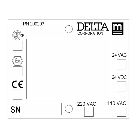
DELTA M Corporation 3242-OM-04 3/27/02 NOTES: Connections to sensors terminal block A (TBA) are factory installed and should not be disconnected in the field. Note Jumpers 1-2, 3-4, and 5-6 must be in place on TBA for proper operation of local electronics. - Page 21 DELTA M Corporation 3242-OM-04 3/27/02 FAILSAFE JUMPER LED LIGHTS GREEN RELAY FUSE PN 200203 SPAN ADJ. CORPORATION 24 VAC TRANSFORMER 24 VDC CAPTIVE SCREWS (2 PLS.) 220 VAC 110 VAC TRIP POINT ADJ. ZERO ADJ. DRAWING FILE: MTF800.DWG/.FCW FIGURE 8.0 microtuf®...
- Page 22 DELTA M Corporation 3242-OM-04 3/27/02 PROBE FLOW RESPONSE FOR THREE MEDIA AND TRIP POINT POT. (R15) SCALE NORMALIZED RESPONSE AFTER CALIBRATION % SPAN CALIBRATION SETTINGS FOR EACH SPAN % SPAN HYDROCARBONS TRIP POINT WATER SIGNAL (mV) 0.001 0.01 0.10 0.001 0.01...
-
Page 23: Calibration - Flow
DELTA M Corporation 3242-OM-04 3/27/02 Calibration – Flow **IMPORTANT** FOR OPTIMUM OPERATION, CALIBRATION MUST BE ACCOMPLISHED AT ACTUAL PROCESS TEMPERATURE AND PRESSURE CONDITIONS IN GASES AND AT ACTUAL PROCESS TEMPERATURE CONDITIONS IN LIQUIDS. See Figures 8.0 and 9.0 for location of potentiometers and LEDS on electronics PCB. -
Page 24: Operation And Calibration Of The Microtuf
DELTA M Corporation 3242-OM-04 3/27/02 ® OPERATION AND CALIBRATION OF THE microtuf LS3200 SERIES SWITCH FOR POINT LEVEL APPLICATIONS Pre-Operational Check The switch is installed and the product level is below sensor level (dry), the following procedure can be used to verify preliminary operation. - Page 25 DELTA M Corporation 3242-OM-04 3/27/02 5.2.3 Alternate Operation (Field Selectable) The relay logic may be reversed by moving the J-2 jumper to position A(1-2). (Refer to Figure 8.0.) RELAY GREEN RELAY CONTACT SENSOR STATUS COIL STATUS STATUS o NC Dry, or Lower Thermal...
-
Page 26: Calibration - Level
DELTA M Corporation 3242-OM-04 3/27/02 Calibration – Level **IMPORTANT** FOR OPTIMUM OPERATION CALIBRATION MUST BE ACCOMPLISHED AT ACTUAL PROCESS TEMPERATURE CONDITIONS. DECREASING THERMAL DISPERSION LIQUID METALS WATER COVER GAS OR AIR HYDROCARBON LIQUIDS FLUIDS VACUUM SENSOR SIGNAL (mV) TRIP POINT POT SCALE... - Page 27 DELTA M Corporation 3242-OM-04 3/27/02 Calibration - Level Using Figure 10.0 as a location guide adjust the system as follows: Remove the instrument enclosure lid by turning ccw. Apply power to the unit. Allow 5 minute warm-up. For optimum calibration results, wet sensor and drain but do not dry.
-
Page 28: Maintenance And Trouble Shooting
Lime deposits can be safely removed by soaking in 20% hydrochloric acid. Warming to 150°F is permissible to speed this process. For unusual cleaning problems, call DELTA M and determine the exact materials of construction and chemical compatibility before using strong acids or unusual cleansers. -
Page 29: Sensor/Electronics Functionality Verification
DELTA M Corporation 3242-OM-04 3/27/02 6.2.2 Sensor/Electronics Functionality Verification ® Turn power off to microtuf Switch. Allow a 5 minute cool down. Measure the resistance of each RTD at pins 1 and 6 of TBA (see Figure 6.0 or 7.0) for the hot RTD and pins 3 and 5 of TBA for the cold RTD. -
Page 30: Specifications
0.5 to 10 seconds no-flow (dry) to flow (wet) and 2 to 60 seconds flow (wet) to no-flow (dry) (application dependent) INPUT POWER: 115 Vac, 50/60HZ standard. (230 Vac, 50/60HZ, 24 Vdc, or 24 Vac optional); 3.1w. maximum. DELTA M PART NO. FUSE REQUIREMENTS (F1): CSA/FM CENELEC 115 Vac: 1/4 amp... -
Page 31: Warranty And Service
Section 7.2, to a repair facility designated by DELTA M and, after repair, DELTA M will prepay transportation to return the product to the customer. This limited warranty only covers failures due to defects in materials or workmanship which occur during normal use. -
Page 32: Volume Flow Conversion Chart
DELTA M Corporation 3242-OM-04 3/27/02 VOLUME FLOW CONVERSION CHART Convert known units to cubic feet per second (CFPS) or gallons per minute (GPM) for use with Chart A.2 TO CONVERT FROM MULTIPLY BY Gallons Per Minute (GPM) Cubic Feet Per 2.228 E-03... -
Page 33: Flow Conversion Chart
FLOW CONVERSION CHART CUBIC FEET CUBIC INCHES MILLILITERS MILLILITERS MILLILITERS MILLILITERS LITERS GALLONS GALLONS BARRELLS CUBIC FEET PER MINUTE PER MINUTE PER MINUTE PER MINUTE PER SECOND PER HOUR PER DAY PER MINUTE PER DAY PER DAY PER SECOND CU FT/MIN CU IN/MIN CC/MIN CC/MIN... - Page 34 DELTA M Corporation 3242-OM-04 3/27/02 This page left blank intentionally.
-
Page 35: 9.3 Flow Of Water Through Schedule 40 Steel Pipe
DELTA M Corporation 3242-OM-04 3/27/02 9.3 FLOW OF WATER THROUGH SCHEDULE 40 STEEL PIPE MODEL NUMBER DESIGNATION AND AVAILABLE OPTIONS... - Page 36 DELTA M Corporation 3242-OM-04 3/27/02 MODEL NUMBER DESIGNATION AND AVAILABLE OPTIONS...
- Page 37 DELTA M Corporation 3242-OM-04 3/27/02 MODEL NUMBER DESIGNATION AND AVAILABLE OPTIONS...
- Page 38 DELTA M Corporation 3242-OM-04 3/27/02 MODEL NUMBER DESIGNATION AND AVAILABLE OPTIONS...
- Page 39 DELTA M Corporation 3242-OM-04 3/27/02 MODEL NUMBER DESIGNATION AND AVAILABLE OPTIONS...
Need help?
Do you have a question about the microtuf FS4200 Series and is the answer not in the manual?
Questions and answers