Table of Contents
Advertisement
Advertisement
Table of Contents

Summary of Contents for Eden C1P2FXBT
- Page 1 Access control C1P2FX C1P2FXBT Technical manual...
-
Page 2: Technical Manual C1P2Fxbt – V1.7 P
Technical manual C1P2FXBT – V1.7 p 2/28... -
Page 3: Table Of Contents
Technical manual C1P2FXBT – V1.7 p 3/28 Contents Contents ..........................3 Acknowledgement ......................... 4 Information and Recommendations ..................5 Technical characteristic ......................6 1) C1P2FX ........................... 6 2) C1P2FXBT ........................6 Typical arrangement for connection ..................7 1) Active aerial ........................7 2) Identification technology using the WIEGAND / Clock&Data protocol ...... -
Page 4: Acknowledgement
Dear client, You have just purchased a “C1P2FX” control unit built by EDEN INNOVATIONS. The entire EDEN INNOVATIONS team would like to thank you for your interest as well as your confidence in our security solution. We hope that you will be completely satisfied with the level of security it provides for your com- pany’s premises. -
Page 5: Information And Recommendations
Technical manual C1P2FXBT – V1.7 p 5/28 Information and Recommendations o Pursuant to European directive UTE C00-200, incorporating directives 89/336 EEC and 92/31 EEC, C1P2FX complies with the following standards: 1. NF EN 50081-1 governing electromagnetic radiation, and 2. NF EN 50082-1 governing electromagnetic susceptibility. -
Page 6: Technical Characteristic
Technical manual C1P2FXBT – V1.7 p 6/28 Technical characteristic 1) C1P2FX Maximum power consumption ..300 mA Power supply voltage ...... 9 – 14VDC Weight including the housing ..1.05 kg Housing dimensions ......175 x 154 x 46 mm ............ -
Page 7: Typical Arrangement For Connection
Technical manual C1P2FXBT – V1.7 p 7/28 Typical arrangement for connection 1) Active aerial Radio receiver (JCM, TECHNO EM,…) Data sheet: 3 wires 100 m (228 ft) Ø 0.6 mm (1/30 in) (SYT recommended) Characteristic: Sensitive connection Screen: Mandatory Simply connect the three wires on the reader to the control unit terminal block as shown. -
Page 8: Identification Technology Using The Wiegand / Clock&Data Protocol
Technical manual C1P2FXBT – V1.7 p 8/28 2) Identification technology using the WIEGAND / Clock&Data protocol WIEGAND: o Proximity card readers (HID, STID, DESTEIR, INDALA, etc.) o Keypads (XPR, etc.) o Biometric readers (SAGEM, etc.) o Radio receivers (JCM, TECHNO EM, etc.) -
Page 9: Solo Reader (Rs485)
Technical manual C1P2FXBT – V1.7 p 9/28 3) SOLO Reader (RS485) 12V DC supply Note: You can connect up to 2 SOLO with a C1P2FX Data sheet: SYT recommended 1200m (2730 ft) Max Ø 0.6 mm (1/30 in) 2 pairs recommended... -
Page 10: Biovein Reader (Rs485)
Technical manual C1P2FXBT – V1.7 p 10/28 4) BIOVEIN Reader (RS485) Note: You can connect up to 2 BIOVEIN with a C1P2FX 12V DC supply RS485 Data sheet: SYT recommended 1200m (2730 ft) Max Ø 0.6 mm (1/30 in) 2 pairs recommended... -
Page 11: Extension Modules Infx2 And Outfx2 (Rs485)
Technical manual C1P2FXBT – V1.7 p 11/28 5) Extension modules INFX2 and OUTFX2 (RS485) ALIMENTATION 12Vcc 12V DC supply RS485 You can connect: o 10 INFX2 maximum to a C1P2FX o 10 OUTFX2 maximum to a C1P2FX Data sheet: SYT recommended 1200m (2730 ft) Max Ø... -
Page 12: Typical Connection Arrangement
Technical manual C1P2FXBT – V1.7 p 12/28 Typical connection arrangement 1) Power failure door activator and electromagnetic door lock triggered by a pow- er failure Non-return diode Power supply +12V 0V Note: In order to avoid all the random malfunctions that may interfere with proper use of the system caused by return currents, it is essential to use and connect the non-return diodes sup- plied with the control unit in accordance with the wiring diagram above. -
Page 13: Standard Door Activator: Triggered By A Voltage Pulse
Technical manual C1P2FXBT – V1.7 p 13/28 2) Standard door activator: triggered by a voltage pulse Non-return diode Power supply +12V 0V Note: In order to avoid all the random malfunctions that may interfere with proper use of the system caused by return currents, it is essential to use and connect the non-return diodes sup- plied with the control unit in accordance with the wiring diagram above. -
Page 14: Using The Menus
Technical manual C1P2FXBT – V1.7 p 14/28 Using the menus The control unit has a configuration menu. To access it, press one of the four buttons below the display. To navigate the menus, use the “+” and “-” keys. To go back to a menu, use the “V” key. To quit, press “C”... -
Page 15: Using The Control Unit Keys
Technical manual C1P2FXBT – V1.7 p 15/28 2) Using the control unit keys The control unit has four keys laid out as below: Scroll Down Key Confirm Key Cancel key Scroll Up Key ( - ) (Confirms a menu /... - Page 16 Technical manual C1P2FXBT – V1.7 p 16/28 o Deleting users: Users are deleted in the same way that they are added. o Browse the list This menu allows you to check the list of users registered in the control unit. The “N:” indicates the user number allocated when it was created while the figure in brackets indicates its position in the list.
- Page 17 This menu allows you to define the communication address (between 1 and 32) using external software (like SenatorFX or SenatorFX.NET). It also allows you to define the communications mode (RS485 / MOD-TCPIP) to communicate with EDEN software. This menu also allows you to force stand-alone mode if your control unit was previously config- ured by software and you now wish to go back into stand-alone mode.
- Page 18 Technical manual C1P2FXBT – V1.7 p 18/28 This menu comprises: Select the input to use as well as the type of contact, to UNAUTHORISED ENTRY INTO ENCLOSURE watch for unauthorized entry into the enclosure. Two successive swipes of a badge through the same reader not allowed.
- Page 19 Technical manual C1P2FXBT – V1.7 p 19/28 STANDARD TYPE 2 Same as the previous menu. READER For the SOLO and BIOVEIN type reader you must enter its identifier (ID on the product serial number label and its security level (false acceptance rate) and its sensitivity level (detection of the presence of a finger on the sensor).
- Page 20 Technical manual C1P2FXBT – V1.7 p 20/28 Automated devices time periods (and free DEVICE TIME PERIODS access) You can set up to 32 time ranges over 8 days (Monday to Sunday plus public holidays) of 10 periods per day. 1) Select the range to be configured using the “+” and “-” scroll keys, then press “V” to confirm.
-
Page 21: Use In Centralized Mode
Technical manual C1P2FXBT – V1.7 p 21/28 Use in centralized mode It is essential that you configure an address for your control unit. To do this, use the control unit menu and go into the “Communication mode” menu to enter the control unit address (1 to 32). -
Page 22: Other Communication Methods
Technical manual C1P2FXBT – V1.7 p 22/28 2) Other communication methods Communication Description Reference method Wired connection of an RS485 Ethernet net- bus on several control units to the C485FX + MOD-TCPIP work (TCP/IP): Ethernet network LAN, WAN, Wired connection of a single... -
Page 23: Connector Blocks
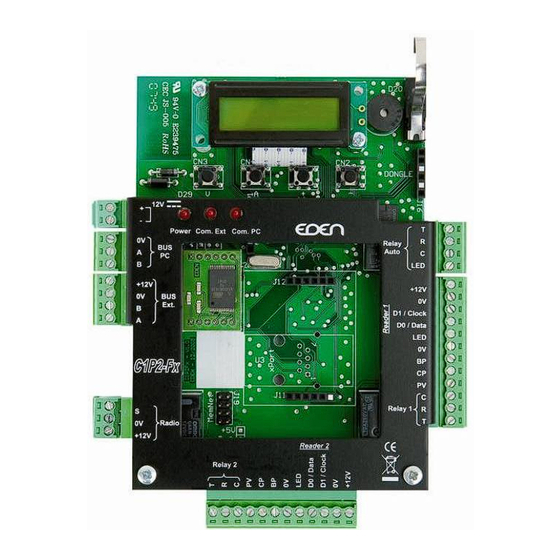
Technical manual C1P2FXBT – V1.7 p 23/28 Connector blocks Power supply +12V BUS 485 PC Control Auto LED +12V BUS 485 +12V Expansion card Entry 3 / Clock / Data1 Entry 4 / Data / Data 0 Reader 1 Push button... -
Page 24: C1P2Fx / C1P2Fx Bt
Technical manual C1P2FXBT – V1.7 p 24/28 C1P2FX / C1P2FX BT 1) Connecting to the power supply Battery 230V~ +12V Phase Earth PASS/C1P2FX Neutral +12V 2) Connecting the battery (not supplied) Battery to be used: 12V, 7Ah (dim. l x d: 151 x 65 mm; 5.94 x 2.56 in) -
Page 25: Check List
Technical manual C1P2FXBT – V1.7 p 25/28 Check list C1P2FX BT Serial number Connector block check Silk-screen print 2 diodes Bag Screws 4*10 Allen key T2,5 Power cable red & black : C1P2FX ... -
Page 26: Notes
Technical manual C1P2FXBT – V1.7 p 26/28 Notes ------------------------------------------------------------------------------------------------------------------------------- ------------------------------------------------------------------------------------------------------------------------------- ------------------------------------------------------------------------------------------------------------------------------- ------------------------------------------------------------------------------------------------------------------------------- ------------------------------------------------------------------------------------------------------------------------------- ------------------------------------------------------------------------------------------------------------------------------- ------------------------------------------------------------------------------------------------------------------------------- ------------------------------------------------------------------------------------------------------------------------------- ------------------------------------------------------------------------------------------------------------------------------- ------------------------------------------------------------------------------------------------------------------------------- ------------------------------------------------------------------------------------------------------------------------------- ------------------------------------------------------------------------------------------------------------------------------- ------------------------------------------------------------------------------------------------------------------------------- ------------------------------------------------------------------------------------------------------------------------------- ------------------------------------------------------------------------------------------------------------------------------- ------------------------------------------------------------------------------------------------------------------------------- ------------------------------------------------------------------------------------------------------------------------------- ------------------------------------------------------------------------------------------------------------------------------- ------------------------------------------------------------------------------------------------------------------------------- ------------------------------------------------------------------------------------------------------------------------------- ------------------------------------------------------------------------------------------------------------------------------- ------------------------------------------------------------------------------------------------------------------------------- ------------------------------------------------------------------------------------------------------------------------------- ------------------------------------------------------------------------------------------------------------------------------- Technical Support : hotline@eden-innovations.com... -
Page 28: Technical Manual C1P2Fxbt – V1.7 P
Technical manual C1P2FXBT – V1.7 p 28/28 Zone Commerciale et Artisanale 670, route de Berre 13510 EGUILLES France www.eden-innovations.com...
Need help?
Do you have a question about the C1P2FXBT and is the answer not in the manual?
Questions and answers