Table of Contents
Advertisement
Quick Links
Advertisement
Table of Contents

Related Manuals for ALUNG Hemolung CR4

Summary of Contents for ALUNG Hemolung CR4
- Page 1 Training Workbook 80450 Pioneered by HL-PL-0256_RB...
-
Page 2: Table Of Contents
Table of Contents 1 Introduction ................... 3 2 Theory of Operation ..............4 3 Hemolung RAS Components .............6 4 Preparation of the Hemolung RAS .......... 15 Part 1 Circuit Priming............16 Part 2 Catheter Insertion .............27 Part 3 Connect Tubing to Catheter ........35 Part 4 Final Checklist ............37 Part 5 Start Blood Pump ............38 5 Managing Therapy and Using the RAS ........39... -
Page 3: Introduction
1 Introduction The Hemolung Respiratory Assist System (RAS) is an integrated, single-use gas exchange system designed to provide partial extracorporeal respiratory support. Oxygen is supplied and carbon dioxide is removed from blood circulated through the Hemolung RAS. The utilization period of this device is validated for up to seven days. -
Page 4: Theory Of Operation
2 Theory of Operation The Hemolung RAS is an integrated, single-use gas exchange system that provides partial extracorporeal respiratory support by providing gas exchange independently of the lungs. Oxygen is supplied and carbon dioxide is removed from blood circulated through the system. This gives the patient’s lungs time to rest and heal. - Page 5 Microscopic Microscopic View View of a Fiber of a Fiber BLOOD GAS EXCHANGE MEMBRANE BLOOD INLET SWEEP GAS INLET BLOOD OUTLET SWEEP GAS OUTLET INTEGRATED CENTRIFUGAL PUMP Page...
-
Page 6: Hemolung Ras Components
3 Hemolung RAS Components The Hemolung RAS is comprised of 3 main components. Hemolung Cartridge • Membrane oxygenator with integrated centrifugal pump Hemolung Catheter • 15.5 Fr dual lumen venous Catheter with insertion accessories, percutaneous, single-stick venous access, femoral (26cm) and jugular (17cm) available Hemolung Controller •... - Page 7 Cartridge Blood Inlet (BLUE) Sweep Gas Inlet Seal Flush Port with Sweep Gas OneWay Outlet Valve Blood Outlet (RED) Catheters Stylet Infusion Lumen (RED) Suture Groove Infusion Drainage Drainage Lumen (BLUE) Port Port Infusion Lumen (RED) Suture Groove Drainage Lumen (BLUE) Drainage Port Infusion...
- Page 8 Hemolung Cartridge Kit Contents Product Description 13000 Hemolung Cartridge Kit - CME IV Pump Configuration Contains all subsequent equipment used to set up therapy 10002 Hemolung Cartridge Membrane oxygenator with integrated centrifugal pump 12100 Hemolung Accessories Kit - SM IV Contains the following equipment to set up or stop therapy: Hemolung Rinse Back Kit...
- Page 9 Hemolung Catheter Kit Contents Product Description 30020 Hemolung 15.5 Fr Femoral Catheter Kit (1) 15.5 Fr Femoral Catheter with Stylet (2) Grip-Lok™ Wide Adhesive Universal Catheter Securement (5) 6, 9, 12, 14, & 16 Fr Dilator (1 of each) (1) 10 mL Syringe (1) #11 Scalpel (1) 18 Ga x 7 cm (2.75 in) Introducer Needle (1) 0.038 in x 100 cm Guidewire with Straightener and...
- Page 10 The Diagnostic ports must be covered at all times during use of the Hemolung system. Removal of the Diagnostic Port cover may result in electrical damage (ESD). The Diagnostic Ports have no user functionality and should only be accessed by ALung authorized service personnel. 10 | Page...
- Page 11 Controller (Front) Blood Flow Sensor Bubble Detectors Tubing Strain Relief Alarm LED Controller Power Button Pump Stop Switch AC Power Present Magnetic Drive Purge Valve Vacuum Canister Bracket Magnetic Fan Cover 11 | Page...
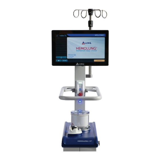
- Page 12 Hemolung Controller Display The display incorporates touch screen controls for interfacing with the system. Screen Lock Battery Status Sweep Gas Oxygen Source Current Mode Settings 12 | Page...
- Page 13 User Interface Display Symbol Area Indicates the following system status: ∞ Sweep gas source ∞ AC power status ∞ Battery status Current Mode Displays current operational mode (device state). Alarm List Active alarms are displayed in this area. Click any alarm listed for additional information.
- Page 14 Therapy Mode Interface Measured CO Removal Rate Displays the measured CO removal rate Measured Blood Flow Rate Displays the measured blood flow rate Removal Rate Trending Graph This area displays the graph for CO removal. Default period is 8 hr but can be cycled through 8 hr, 24 hr, 7 days, or 14 days.
-
Page 15: Preparation Of The Hemolung Ras
4 Preparation of the Hemolung RAS The preparation of the Hemolung RAS includes 4 main parts: Part 1 Circuit Priming Part 2 Catheter Insertion Part 3 Connect Tubing to Catheter Part 4 Final Checklist Part 5 Start Blood Pump The following supplies are required for circuit preparation: •... -
Page 16: Part 1 Circuit Priming
Part 1 Circuit Priming Step 1 Follow On Screen Instructions Follow the on screen instructions and press the NEXT button to advance through the procedure. Step 2 Remove Old Soda Lime Pull the old soda lime column out of the Controller and remove the reusable end caps. - Page 17 Step 3 Assemble and Attach New Soda Lime Column Remove the red shipping plugs from the new column. Attach the reusable end caps to the column and install the new soda lime column on the Controller. Step 4 Hang the Saline for Seal Flush Hang the container of saline for providing the seal flush on the Hemolung Controller.
- Page 18 Step 6 Prepare Priming Solution Prepare a priming solution of at least 500 mL and hang on the Controller. One (1) unit (U) heparin per milliliter (mL) saline is recommended as the priming solution. Other priming fluids have not been qualified for use with the Hemolung RAS.
- Page 19 Step 9 Connect Infusion Pump and Run at 30 mL/hr Remove the cap from the seal flush port on the Cartridge, then attach the check valve to the port, and connect the IV line. Open the clamp on the IV administration set and start the seal flush infusion at 30 mL/ hr.
- Page 20 Step 12 Prime the Cartridge Hold the Hemolung Cartridge upside- down with the red blood outlet port facing up. Open the white clamp located near the priming spike. This will start the flow of priming solution into the Hemolung circuit. Walk the air through the tubing until it is completely primed and solution begins to enter the Cartridge.
- Page 21 Step 15 Close the White Clamp Once the Cartridge is full, close the white clamp. Step 16 Open Blue Clamp and Remove Air Open the blue clamp to allow any trapped air to travel up and into the recirculation bag. Tap the line to assist in this process if needed.
- Page 22 Step 18 Apply Petroleum Jelly, Install Cartridge and Tubing Place the Cartridge on the Controller as shown. Apply a small amount of petroleum jelly to the area of the tubing that sits in the blood flow sensor. Place the tubing into the bubble detector and flow sensor, and close the flow sensor door.
- Page 23 Step 21 Cap Ports and Place Canister Cap the large port labeled "ACCESSORY" and the small port labeled "TANDEM". These ports will not be used. Hang the vacuum canister on the Controller using the bracket. Routinely replace the vacuum canister every 24 hours to ensure the integrity of the canister and overall system performance.
- Page 24 Use care when placing the silicone tubing into the purge valve. Using too much force or excessive stretching can cause damage to the tubing. Step 24 Connect Sweep Gas Supply Tube Connect the sweep gas supply tube (with bacterial filter) to the sweep gas port on the Controller as shown.
- Page 25 Step 27 Start Recirculation Press the NEXT button to begin the recirculation process, the pump will start automatically. The user is responsible for ensuring that no air bubbles are left in the circuit before continuing. Step 28 Allow the System to Self-Test If an error is found in the system during recirculation, the...
- Page 26 Step 29 Successful Completion When all recirculation checks have passed, and air has been removed from the circuit, press the CONTINUE button to proceed to the Settings screen. Step 30 Providing Supplemental O If deemed necessary by the physician, the Hemolung RAS can provide supplemental oxygenation to the patient through the use of oxygen as the sweep gas.
-
Page 27: Part 2 Catheter Insertion
Part 2 Catheter Insertion Step 1 Prepare Syringes and Insert Stylet with Priming Adapter into Infusion Lumen (Red) Open the Hemolung Catheter Kit and prepare three 20 mL and one 10 mL saline syringe flushes. Using sterile technique, insert the stylet with RED priming adapter into the Infusion Lumen (RED), placing the priming adapter over the barb connector. - Page 28 Step 4 Reinsert Stylet Remove the syringe and replace the stylet into the Infusion Lumen (RED). Step 5 Flush Drainage Lumen (Blue) Connect one of the 20 mL syringes to the Drainage Lumen (BLUE) priming adapter. Hold the Catheter with the tip up and flush the Drainage Lumen (BLUE) with approximately 10 mL of saline.
- Page 29 Step 7 Puncture Vessel • With a sterile scalpel blade, nick the skin over the target vessel. • Attach a 10 mL syringe to the introducer needle and insert the needle into the target vessel using a shallow angle (more parallel to the target vessel than a standard 45° approach).
- Page 30 Prior to connection to the Hemolung RAS, a target ACT >150 seconds or aPTT > 1.5 times baseline is recommended. If a significant delay occurs between administering the heparin bolus and starting Hemolung therapy, verify the anticoagulation level and re-bolus as necessary. Proceed to the following step while the Heparin circulates through the patient.
- Page 31 Step 9 Dilate Vessel Slide the dilator onto the guidewire advancing it through the skin and into the vessel using the same original insertion angle as the guidewire. Using the same shallow angle approach could reduce the potential risk of guidewire kinks or that a vessel is punctured.
- Page 32 6. Ensure adequate tissue relaxation with each dilation step. Consider repeatedly inserting/retreating the dilator at each step until the tissue is fully relaxed and resistance to insertion is minimal. Utilize rotational motion to gently advance the dilators through the tissue. Incorrect: Dilator inserted at a different angle than the guidewire resulting in kinking in the subcutaneous tissue.
- Page 33 Step 10 Insert Catheter Feed the distal section of the stylet over the guidewire. Proper Catheter location will be indicated by free blood flow. Verify the advancement, positioning, and placement of the Catheter using appropriate imaging guidance. For JUGULAR insertion, advance the Catheter tip to the junction of the superior vena cava and right atrium.
- Page 34 If a delay occurs in establishing extracorporeal blood flow, the Catheter lumens should be flushed continuously with an appropriate intravenous solution to prevent clotting. Step 13 Secure Catheter Femoral Catheter Secure the Catheter hub to the skin using a strong suture. The suture should be placed in the groove of the Catheter hub...
-
Page 35: Part 3 Connect Tubing To Catheter
Part 3 Connect Tubing to Catheter Step 1 Close All Clamps Press NEXT to proceed to Blood Tubing Connection. Close all clamps in the circuit. The plastic sheath surrounding the blood tubing is provided for sterile handling. Take extra care handling the blood tubing area surrounding the Catheter connection. - Page 36 Step 3 Connect FROM PATIENT (Blue) Tubing Set to Catheter Disconnect the FROM PATIENT (BLUE) Tubing Set from the Y-connector. Using a wet-to-wet technique, connect the tube to the blue lumen on the Catheter. Ensure that the tubing is placed completely over the barb connector for a secure connection.
-
Page 37: Part 4 Final Checklist
Part 4 Final Checklist After pressing NEXT on the final Patient Connection screen, the Final Check screen will be displayed. All items must be completed and manually checked off before the Start Therapy button becomes accessible. Step 1 Check Tubing Connections Check all tubing connections to make sure they are properly connected. -
Page 38: Part 5 Start Blood Pump
Part 5 Start Blood Pump After connecting the primed extracorporeal circuit to the Catheter, Therapy is initiated by pressing Start Therapy after the final checklist. The pump will start automatically, which causes blood to flow through the extracorporeal circuit and sweep gas to pass through the Cartridge membranes. -
Page 39: Managing Therapy And Using The Ras
5 Managing Therapy and Using the RAS When determining initial sweep gas flow settings, one should take into account that CO removal when starting Therapy is nearly instantaneous. The impact to the patient varies based on pCO level and patient status. Raising the sweep gas flow setting too quickly could result in the patient becoming hypocapnic. -
Page 40: Controlling Pump Speed
Controlling Pump Speed Increasing the blood flow rate will increase CO removal. The blood flow rate is adjusted by varying the pump speed using the Controller. The pump speed can be set between 500 and 1400 RPM to achieve the desired blood flow rate. Pump speed can only be changed from the Main Therapy Screen. -
Page 41: Controlling Sweep Gas Flow
Controlling Sweep Gas Flow Increasing the sweep gas flow rate will increase CO removal. The sweep gas flow rate can be set to 0 L/min, or be adjusted between 1.0 and 10.0 L/min. The sweep gas flow rate can only be changed from the Main Menu. -
Page 42: Start/Stop Blood Pump
Start/Stop Blood Pump The pump can be turned on and off with the on screen Start/Stop Pump button. The pump may also be shut off using the Pump Stop Switch. This will immediately stop the pump and display an E-Stop Engaged alarm. -
Page 43: Therapy Screen
Therapy Screen The “Therapy Screen” displays plot lines for the user set sweep gas flow and blood pump RPM as well as the measured CO removal and blood flow rate to detect trends SWEEP GAS SET POINT MEASURED SWEEP GAS RPM SET POINT MEASURED BLOOD FLOW... -
Page 44: Menu Screens
Screen Lock To avoid accidental button presses, it is recommended to lock the screen during therapy. Press the lock icon in the upper left corner of the screen to lock it. To unlock the screen press it again and then press UNLOCK on the popup message. Menu Screens Main Menu The settings can be... - Page 45 System To access the language selection, data download, and remote service, select the system tab from within the settings menu. This is accessed by pressing the settings ( ) icon at the bottom left of the screen. Language Select between different languages by pressing the settings ) icon at the...
-
Page 46: Daily Vacuum Canister Replacement
Daily Vacuum Canister Replacement The sweep gas vacuum canister must be changed daily to ensure adequate sweep gas flow. No changes or operations to the therapy parameters or blood pump are necessary to complete this task. An alarm will temporarily appear on the display screen during and following the vacuum canister change and should clear within approximately 1 minute. -
Page 47: Change Seal Flush Fluid
Step 3 Attach Sweep Gas Elbow Disconnect the sweep gas elbow from the vacuum canister port labeled “PATIENT” and attach it to the same port on the new vacuum canister. Change Seal Flush Fluid Replenish seal flush fluid according to hospital procedures using normal saline. -
Page 48: Weaning & Ending Therapy
6 Weaning & Ending Therapy Weaning from Therapy is done by progressively reducing the amount of CO removal while closely monitoring the patient. The sweep gas flow rate can be reduced to zero while circuit blood flow is maintained in order to evaluate the patient’s response to withdrawing Therapy. - Page 49 Step 2 Hang the saline bag on the Controller. Squeeze the plastic chamber to prime the IV tube. Step 3 Clamp the FROM PATIENT (BLUE) Tubing approximately 20 cm (8 in) from the Catheter connection using the attached ratchet clamp or another tubing clamp.
- Page 50 Step 5 After ensuring that the clamps are closed, cut the FROM PATIENT (BLUE) Tubing between the tubing clamp and the Catheter barb connector in the area that was previously cleaned. Step 6 Using a wet-to-wet technique, connect the priming spike barb connector to the FROM PATIENT (BLUE) Tubing, ensuring no air is trapped in the tubing.
- Page 51 Step 8 Once the blood is returned, clamp the FROM PATIENT (BLUE) Tubing and the priming spike barb connector using the attached ratchet clamps. Step 9 Close the TO PATIENT (RED) Tubing and remove the Catheter in the same manner as any other large bore central venous catheter.
-
Page 52: Without Blood Rinse Back
Without Blood Rinse Back The attending physician may decide it is not necessary to return blood to the patient and discard the entire circuit. Step 1 Press the STOP PUMP button to stop the Hemolung Cartridge pump. Step 2 Clamp both Catheter lumens with the attached slide clamps. Step 3 Clamp both blood tubes approximately 15 cm (6 in) from the Catheter connection using the attached ratchet clamps or other... -
Page 53: Troubleshooting
7 Troubleshooting Management of Alarms The device prioritizes alarm notifications. The alarms are displayed in the notification area on the left side of the screen. If multiple alarms occur, the highest priority alarm will be listed at the top. The alarms will appear individually in their corresponding color code. -
Page 54: Critical Errors And Accidental Termination Of Therapy
Critical Errors and Accidental Termination of Therapy If Therapy has been stopped due to a critical error, user error, battery depletion or other unforeseen circumstances, the user must turn the Controller off before the device can become operational. In these cases the Hemolung Controller can skip setup procedures and immediately enter therapy mode by pressing the Recover button on the Welcome screen. - Page 55 Step 3 Read all warnings and press the RECOVER button to proceed to therapy mode. Step 4 Press the PUMP START button to begin therapy. 55 | Page...
-
Page 56: Device Maintenance
Do not remove the instrument covers on the Hemolung Controller. The Hemolung RAS does not have any user serviceable parts and the battery cannot be replaced by the user. Contact ALung or your medical equipment distributor for service or repairs. Cleaning Clean the Hemolung Controller with a damp sponge and a mild soap solution and/or a 10% bleach solution. -
Page 57: Storage
Contact Information Dedicated 24/7 Support France: 0800-918846 Germany: 0800-181-6344 UK: 0-808-189-1190 All others: +1-724-506-5149 ALung Technologies, Inc. 2500 Jane Street Suite 1 Pittsburgh, PA 15203 USA +1-412-697-3370 +1-412-697-3376 Web www.alung.com 57 |... - Page 58 Notes 58 | Page...
- Page 59 Notes 59 | Page...
- Page 60 Pioneered by ALung Technologies, Inc. 2500 Jane Street, Suite 1 Pittsburgh, PA 15203 USA tel: +1 412-697-3370 fax: +1 412-697-3376 email: sales@alung.com 80450 www.alung.com HL-PL-0256_RB...
Need help?
Do you have a question about the Hemolung CR4 and is the answer not in the manual?
Questions and answers