Table of Contents
Advertisement
Advertisement
Table of Contents

Subscribe to Our Youtube Channel
Summary of Contents for Nordberg A2020
- Page 1 140569 A2020 INSTRUCTION MANUAL GP Series Cone Crushers Operator version 3/01...
-
Page 2: Table Of Contents
TABLE OF CONTENTS General _______________________________________________________________ 4 Nordberg A2020 ______________________________________________________________4 User interface ________________________________________________________________4 Crusher control ________________________________________________________ 6 Crusher control display ________________________________________________________6 Selecting operation mode_______________________________________________________6 2.2.1 Manual control mode______________________________________________________________ 7 2.2.2 Setting control mode ______________________________________________________________ 7 2.2.3 Load control mode________________________________________________________________ 8 2.2.4 Feeder control ___________________________________________________________________ 8 2.2.5... - Page 3 Lubrication oil heater and cooler control circuits _______________________________________ 23 5.3.4 Lubrication pump control circuit ____________________________________________________ 23 System faults ________________________________________________________________24 Error messages concerning software updating and network management _____________24 Appendices 1. Circuit diagrams and connections for A2020 2. Spare parts book Version 3/01 Page 3/25...
-
Page 4: General
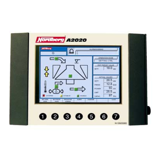
1. General Nordberg A2020 The crusher controller A2020 is used for controlling GP and HP crushers. The system can be installed on fixed and moving plants. A2020 is a computer system designed for field operation, and it consists of three decentralised components: •... - Page 5 Display screen The user interface screen is divided into seven windows. The function of the windows is described below, starting clockwise from the top left corner. Window 1: Crusher type. Window 2: Alarms and warnings. The alarm light at left in this window turns red for alarm and yellow for warning.
-
Page 6: Crusher Control
2. Crusher control Crusher control display To enter the crusher control display, press F1 in the main menu. In the crusher control display you can choose operating mode; preset values; alarm, warning, and event data; and calibrating functions. The crusher control screen shows the following functions: •... -
Page 7: Manual Control Mode
Nordberg A2020 system manager does see a loss of DCU <--> PCM/LCM communication for longer than 2 minutes. Manual control mode may also be forced by system as a result of serious fault on control modes. -
Page 8: Load Control Mode
2.2.3 Load control mode On load control mode, the crusher controller compares the actual pressure and power values with the preset ones. If the pressure or power actual value is bigger than preset value + hysteresis (hysteresis values are set in the configuration), setting increases until actual value is less than preset value + hysteresis value. -
Page 9: Operation Data
Operation data 2.4.1 Trends Trends describe the crusher's actual values. The horizontal axis indicates time and the vertical axis the actual system value at the specific moment. The time scales you can choose between are 6 minutes, 60 minutes, 6 hours, and 24 hours. The vertical axis scales itself automatically to give the most precise view possible. -
Page 10: Field Data
The table below describes the functions of the trend screen: Function Description of function Setting trend Setting [mm / in] Power trend Power [kW / hp] Pressure trend Pressure [bar / psi]. Capacity trend Capacity [mtph / stph] (tons per hour). Timescale 24 h <-- Changes the time scale shown on the screen. -
Page 11: Alarms
Reading field data: • Enter crusher control display (press F1 in main menu). • Select LOGBOOK (press F3). • Choose field data (press F2). • Press F7 to exit. Function Description of function. Timescale, day <-- Go over to previous time scale. Timescale, day -->... - Page 12 Reading alarm and warning data: • Enter crusher control display (Press F1 in main menu). • Select ALARMS (Press F4). Function keys in alarm mode are as follows: Function Description of function Select Selects event. Acknowledge all Acknowledges all events. Move up Moves cursor upwards on the list.
-
Page 13: Calibration
Calibration Methods of calibration: manual calibration and contact calibration. 2.6.1 Manual calibration In manual calibration, the crusher's setting is measured using e.g. a piece of lead. See crusher’s instruction manual for detailed information about how to perform measuring. After you have measured the actual setting, do this: •... -
Page 14: Contact Calibration
• Highlight manual calibration in the menu (F5 up, F6 down). • Select manual calibration (press F1) • Feed in new setting (F1 increases, F2 decreases in 0.1 mm / 0.01 inch increments). • Acknowledge calibration (press F3) • Press F7 to exit. 2.6.2 Contact calibration Contact calibration is allowed to do only in fine crushers! In the contact calibration, the crusher's current setting is checked by running liner against liner. -
Page 15: Trends
Trends Reading trends • Enter main menu. • Choose Diagn. (press F2). • Choose trends (press F1) • Press F7 to exit. The table below describes the functions of the trend screen: Function Description of function Tank temperature Oil temperature in the tank [_C /_F]. Return temperature Crusher lubrication return oil temperature [_C / _F]. -
Page 16: Input And Output Data
Timescale Changes the time scale shown on the screen. The time --> 6 min alternatives are 24 hours, 6 hours, 60 minutes (1 h), and 6 minutes. Close Exit to diagnostics display. Input and output data The diagnostics monitor the condition of sensors and actuators. The system also indicates the I/O statuses of the control units. -
Page 17: Starting Lubrication
The crusher is started and stopped through the start/stop menu. By selecting F2 in the main menu you enter the diagnostics display, and from there by pressing F3 to start/stop menu. The crusher and its auxiliary devices can be started one by one or in the sequence. When starting in a sequence, the crusher's controller automatically starts the lubrication, the crusher, and the feeding device in steps while controlling starting conditions for each device. -
Page 18: Starting Crusher
3.4.2 Starting crusher • Enter diagnostics display (Press F2 in main menu). • Select start/stop (Press F3). • Highlight crusher in the start-stop-sequences menu (F5 up, F6 down). • Start crusher (press F1). Lubrication unit and the crusher will start now in sequence. There is a delay between the startings. -
Page 19: Stopping Crusher
3.4.5 Stopping crusher • Enter diagnostics display (press F2 in main menu). • Select start/stop (press F3). • Highlight crusher in the start-stop-sequences menu (F5 up, F6 down). • Stop crusher (press F2). Feeding device and the crusher will now stop in sequence. There is a delay between the stoppings. -
Page 20: Error/Information Messages
Select language • Enter main menu (Press F7 a sufficient number of times). • Select system parametres (Press F3). • Select user setup (Press F1). • Select language settings (Press F1). • Highlight desired language (F5 up, F6 down). • Select language (Press F4). -
Page 21: Lubrication Oil Temperature In Tank
• You have reached the crusher's maximum pressure. Decrease crusher loading (increase setting or decrease feed). Fault on pressure sensor! • The output of the pressure sensor is below working limit. There must be a fault in the sensor or the cable. Check the sensor and cable. Replace if necessary. Fault on pressure sensor! •... -
Page 22: Power
• Lubrication oil temperature sensor message is over working limit. Check the sensor and cable. Replace if necessary. Return oil sensor ok. • There was a fault in lubrication oil temperature sensor. Now the sensor has recovered. 5.1.5 Power Power limit exceeded! •... -
Page 23: Faults In Cables And Connectors
Lubr. oil heater safety device OK. Lubr. oil heater safety device tripped. • Process is not stopped. Only an alarm is given. Adjustment pump safety device OK Adjustment pump safety device tripped. • Process is not stopped. Decreasing the crusher's setting is disabled. Increasing is still possible. -
Page 24: System Faults
System faults Adjusting fault! • The controller was trying to increase and decrease setting at the same time. This cannot be done. After a delay feed to the crusher was stopped. Filter jam • There is a filter jam in lubrication oil. Check the filter and replace if necessary. Lubrication problem, process stopped! •... - Page 25 LCM recovered. • LCM did not send its status earlier, but has now recovered and is working properly. PCM has become unreliable. • Module answers wrong to system queries. Check the connectors and cables. If this does not help, contact maintenance. LCM has become unreliable.
-
Page 26: Circuit Diagrams And Connections For A2020
Appendix 1 Circuit diagrams and connections for A2020... - Page 54 Appendix 2 Spare Parts Book...
- Page 55 924140 Parts REF. DESCRIPTION I/O-MODULE FASTENING BRACKET ELECTRIC SWITCH DISPLAY UNIT PCMCIA CARD CONNECTOR CABLE CONNECTOR RESISTOR 1 X1 PIN, MALE 1 X2 PIN, MALE 1 X3 PIN, MALE 1 X4 PIN, MALE 1 X5 PIN, MALE 1 X6 PIN, MALE 1 X7 PIN, MALE...
Need help?
Do you have a question about the A2020 and is the answer not in the manual?
Questions and answers