
Summary of Contents for W.E.S.T. Elektronik POS-123-P
- Page 1 Technical Documentation POS-123-U POS-123-P POS-123-U-SSI Universal positioning module, alternatively with power output stage or SSI interface...
-
Page 2: Table Of Contents
CONTENTS General Information ..............................4 Order number ..............................4 Scope of supply .............................. 4 Accessories ..............................4 Symbols used ..............................5 Using this documentation ..........................5 Legal notice ..............................5 Safety instructions ............................6 Characteristics ................................. 7 Compatibility ..............................8 Device description ............................ - Page 3 5.6.6 CTRL (Deceleration characteristics) ....................31 Output signal adaptation ..........................32 5.7.1 MIN (Deadband compensation) ......................32 5.7.2 MAX (Output scaling) ........................... 32 5.7.3 TRIGGER (Response threshold for the MIN parameter)..............32 5.7.4 OFFSET (Zero correction) ........................33 5.7.5 SIGNAL:U (Type and polarity of the output signal) ................33 Special commands ............................
-
Page 4: General Information
POS-123-U -2030 sensor interface POS-123-P-2030 - with integrated power output stage up to 2,6 A (see additional information) POS-123-U-SSI-2030 - with programmable output (±10 V differential output or 4… 20 mA), SSI sensor interface and 0… 10 V output as a diagnosis signal for the SSI sensor... -
Page 5: Symbols Used
1.4 Symbols used General information Safety-related information 1.5 Using this documentation Structure of the documentation: The standard product is descibed up to chapter 6. The extensions like POWER STAGE or SSI-INTERFACE are described in the chapters ADDITIONAL INFORMATION. 1.6 Legal notice W.E.St. -
Page 6: Safety Instructions
1.7 Safety instructions Please read this document and the safety instructions carefully. This document will help to define the product area of application and to put it into operation. Additional documents (WPC-300 for the start-up software) and knowledge of the application should be taken into account or be available. General regulations and laws (depending on the country: e. -
Page 7: Characteristics
2 Characteristics This electronic module has been developed for controlling hydraulic positioning drives. Proportional valves with integrated or external electronics can be controlled with the differential output. The internal profile generation is optimized for stroke-dependent deceleration or the NC control mode. The controller and the controller settings are adapted to typical requirements and thus permit rapid and uncritical optimization of the control behavior. -
Page 8: Compatibility
2.1 Compatibility As a result of further developments some smaller changes have to be taken in consideration. Functionality: 1. Downward compatible to the older modules. 2. 100 % wiring compatible. 3. Baud rate: The default baud rate has changed from 9600 baud to 57600 baud. This is adaptable in WPC-300: OPTIONS/SETTINGS/INTERFACE. -
Page 9: Device Description
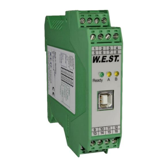
2.2 Device description Standard module – for the P-Version look at point 7.2 99,0000 mm 23,0000 mm 9 10 11 12 13 14 15 114,0000 mm Made in Germany Date: Add.: W.E.ST. Elektronik D-41372 Niederkrüchten Homepage: http://www.w-e-st.de Typenschild und Anschlussbelegung Type plate and terminal pin assignment W.E.ST. -
Page 10: Use And Application
3 Use and application 3.1 Installation instructions This module is designed for installation in a shielded EMC housing (control cabinet). All cables which lead outside must be screened; complete screening is required. It is also necessary to avoid strong electro-magnetic interference sources being installed nearby when using our open and closed loop control modules. -
Page 11: Typical System Structure
3.2 Typical system structure This minimal system consists of the following components: (*1) Proportional valve (or control valve): the valve type determines the precision. It is expedient to use control valves with integrated electronics. (*2) Hydraulic cylinder (*3) Integrated analogue or SSI position sensor (alternatively also with external position sensor) (*4) POS-123-* control module (*5) - Page 12 In manual mode (START disabled) the drive can be moved by means of HAND+ or HAND-. The drive moves under open-loop control at the programmed manual speeds. When the HAND (+ or -) signal is switched off, the current actual position is accepted as the required position and the drive comes to a controlled stop.
-
Page 13: Commissioning
3.4 Commissioning Step Task Installation Install the device in accordance with the circuit diagram. Ensure it is wired correctly and that the signals are well shielded. The device must be installed in a protective housing (control cabinet or similar). Switching on for the first Ensure that no unwanted movement is possible in the drive (e. -
Page 14: The Start-Up Assistant
3.5 The Start-Up assistant The function of the start-up assistant is available on request „Start-up-assistant for positioning drives”. This assistant is available in special versions of the positioning controllers only. Page 14 of 58 POS-123-*-2030 23.08.2019... -
Page 15: Technical Description
4 Technical description 4.1 Input and output signals Connection Supply PIN 3 Power supply (see technical data) PIN 4 0 V (GND) connection. Connection Analogue signals External speed demand (V), range 0… 10 V or 4… 20 mA (scalable) PIN 9 / 10 Position demand value (W), range 0…... -
Page 16: Led Definitions
4.2 LED definitions LEDs Description of the LED function GREEN Identical to the READY output. OFF: No power supply or ENABLE is not activated System is ready for peration Flashing: Error discovered Only active when SENS = ON YELLOW A Identical to the STATUS output. -
Page 17: Circuit Diagram
4.3 Circuit diagram Page 17 of 58 POS-123-*-2030 23.08.2019... -
Page 18: Typical Wiring
4.4 Typical wiring Power Supply Error / InPos Ready Enable Start Hand+ Hand- Analogue velocity 0... 10V / 4... 20 mA Power amplifier interface / proportional valve +/- 10V (differential input) 4... 12... 20mA PIN 15 to PIN 12 Screen Analogue Input 0... -
Page 19: Technical Data
4.6 Technical data 12… 30 (incl. ripple) Supply voltage (U [VDC] [mA] Current requirement <100 External protection 1 medium time lag Digital inputs OFF : < 2 ON : > 10 [kOhm] Input resistance Digital outputs OFF: < 2 ON: max. U [mA] Maximum output current 0…... -
Page 20: Parameters
5 Parameters 5.1 Parameter overview Group Command Default Unit Description Basic parameter Changing language help texts MODE Parameter view SENS Malfunction monitor EOUT 0,01 % Output signal if no ready HAND:A 3330 0,01 % Output signal in manual mode HAND:B -3330 0,01 % INPOS... - Page 21 Group Command Default Unit Description MAX:A 10000 0,01 % Output scaling MAX:B 10000 0,01 % TRIGGER 0,01 % Deadband compensation trigger point OFFSET 0,01 % Output offset value SIGNAL:U U+-10 Type of output signal and polarity Special commands Drift compensator Control parameter of the drift compensator DC:AV 0,01 %...
-
Page 22: Configuration
5.2 Configuration 5.2.1 LG (Changing the language) Command Parameters Unit Group x= DE|EN Either German or English can be selected for the help texts. CAUTION: After changing the language settings, the ID button (SPEED BUTTON) in the menu bar (WPC-300) must be pressed (module identification). 5.2.2 MODE (Switching between parameter groups) Command... -
Page 23: Eout (Output Signal: Ready = Off)
5.2.4 EOUT (Output signal: READY = OFF) Command Parameters Unit Group EOUT x= -10000… 10000 0,01 % Output value in case of a detected error or a deactive ENABLE input. A value (degree of valve opening) for use in the event of a sensor error (or the module is disabled) can be defined here. This function can be used if, for example, the drive is to move to one of the two end positions (at the specified speed) in case of a sensor error. -
Page 24: Inpos (In Position Range)
5.2.6 INPOS (In position range) Command Parameters Unit Group INPOS x= 2… 200000 µm This parameter is entered in µm. The INPOS command defines a range for which the INPOS message is generated. This function monitors the failure between the command and actual position. If the failure is less than the programmed value a INPOS message at the status output (see Pin description). -
Page 25: N_Range:x (Nominal Range Of The Sensor)
5.3.3 N_RANGE:X (Nominal range of the sensor) Command Parameter Unit Group N_RANGE:X x x= 10… 10000 EASY N_RANGE (nominal range or nominal stroke) is used to define the length of the sensor. This value should be always higher than SYS_RANGE. The control parameter cannot be calculated correctly in case of wrong val- ues. -
Page 26: Using Of The Commands Sys_Range, N_Range:x And Offset:x
5.3.5 Using of the commands SYS_RANGE, N_RANGE:X and OFFSET:X The application scaling will be done by these three commands. In this example the system is defined by a length of 120 mm of the sensor, a working stroke of 100 mm of the cylinder and an offset of 5 mm. These pa- rameters have to be typed in and the axis is driving between 5 mm and 105 mm of the sensor stroke and be- tween 0 mm and 100 mm of the cylinder stroke. -
Page 27: Speed Commands
5.4 Speed commands The SIGNAL:V command is used to switch over between external or internal speed limitation. SIGNAL:V = OFF Internal speed limitation (VELO command) SIGNAL:V = U0-10 External speed limitation PIN 9/10 is used for external speed limitation 5.4.1 VELO (Internal speed demand value) Command Parameters... -
Page 28: Profile Generator
5.5 Profile generator 5.5.1 VMODE (Methode of positioning) Command Parameters Unit Group VMODE x= SDD|NC The fundamental control structure can be changed with this parameter. SDD: Stroke-Dependent Deceleration. In this mode, stroke-dependent deceleration is activated. This mode is the default mode and is suitable for most applications. With stroke-dependent deceleration the drive comes to a controlled stop at the target position. -
Page 29: Control Parameter
5.6 Control parameter 5.6.1 A (Acceleration (ramp) time) Command Parameters Unit Group i= A|B VMODE=SDD x= 1… 5000 Ramp function for the 1 and 3 quadrants. The acceleration time for positioning is dependent on the direction. “A” corresponds to connection 15 and “B” corresponds to connection 16 (if POL = +). -
Page 30: Loop Gain Setting)
5.6.3 (Loop gain setting) Command Parameters Unit Group V0:i i= A|B VMODE = NC x= 1… 400 This parameter is specified in s (1/s). In NC Mode normally the loop gain is specified rather than the deceleration stroke The internal gain is calculated from this gain value together with the parameters VMAX and SYS_RANGE. ... -
Page 31: Pt1 (Timing Of The Controller)
5.6.5 PT1 (Timing of the controller) Command Parameter Unit Group x= 0… 300 This parameter can be used to change the internal timing of the control function. Hydraulic drives are often critical to control especially in case of high speeds and very fast valves. The PT1 filter can be used to improve the damping rate and allows therefore higher loop gains. -
Page 32: Output Signal Adaptation
5.7 Output signal adaptation 5.7.1 MIN (Deadband compensation) 5.7.2 MAX (Output scaling) 5.7.3 TRIGGER (Response threshold for the MIN parameter) Command Parameters Unit Group i= A|B MIN:i x= 0… 6000 0,01 % MAX:i x= 3000… 10000 0,01 % TRIGGER x= 0… 4000 0,01 % The output signal to the valve is adjusted by means of these commands. -
Page 33: Offset (Zero Correction)
5.7.4 OFFSET (Zero correction) Command Parameters Unit Group OFFSET x= -4000… 4000 0,01 % This parameter is entered in 0,0 1% units. The offset value is added to the output value. Valve zero offsets can be compensated with this parameter. 5.7.5 SIGNAL:U (Type and polarity of the output signal) Command Parameter... -
Page 34: Special Commands
5.8 Special commands 5.8.1 Drift compensation / high accurate positioning The high accurate positioning or the drift compensation can be used in case of external influence which is lim- iting the positioning accuracy. This function could be critical if limit cycling by wrong parameterization or the system behavior was not taken into account. - Page 35 Typical setup Valve pressure gain: 2,5 %; the activation point has to be set to 3… 5 % (DC:AV 300… 500). Valve hysteresis: 0,5 %; the deactivation point has to be set to 0,7… 1,0 % (DC:DV 70… 100). The lower the value the better the accuracy.
-
Page 36: Ainmode
5.8.2 AINMODE The AINMODE is used to define the kind of parameterizing of the analogue inputs. The EASY mode (DEFAULT) supports a simple and application oriented input scaling. The MATH mode supports the free input scaling by a linear equation. This mode is compatible to our older modules. -
Page 37: Process Data
Typical settings: Command Input Description AIN:X 1000 1000 0… 10 V Range: 0… 100 % AIN:X 1000 V OR 1… 9 V Range: 0… 100 %; 1 V = 1000 used for the offset and AIN:X 1000 1000 V gained by 10 / 8 (10 V divided by 8 V (9 V -1 V)) AIN:X 500 V OR 0,5…... -
Page 38: Appendix
6 Appendix 6.1 Failure monitoring Following possible error sources are monitored continuously when SENS = ON/AUTO: Source Fault Characteristic Command signal PIN 13 Out of range or broken wire The output will be switched off. 4... 20 mA Feedback signal PIN 14 Out of range or broken wire The output will be switched off. - Page 39 FAULT CAUSE / SOLUTION ENABLE is active, the The flashing READY LED signals that a fault has been detected by the module. The fault could be: READY LED is flashing. A broken cable or no signal at the input (PIN 13 or PIN 14), if 4… 20 mA signals are parameterized.
-
Page 40: Description Of The Command Structure
6.3 Description of the command structure The command structure: [nnnn:i x] or [nnnn Meaning: nnnn - used for an arbitrary command name nnnn: - used for an arbitrary command name, expandable by an index. Indexed commands are indicated by the sign “:” i oder I - is a dummy for the index. -
Page 41: Additional Information: Power Output Stage
7 ADDITIONAL INFORMATION: Power output stage 7.1 General function The power output stages have been developed for controlling proportional valves without spool position feedback. The output stage is controlled by the microcontroller on the basic module by means of pulse width modulated signals, and the current is continuously controlled. -
Page 42: Device Description
7.2 Device description 99,0000 mm 45,0000 mm 13 14 15 16 25 26 27 28 13 14 15 16 29 30 31 32 114,0000 mm Made in Germany Date: Add.: W.E.ST. Elektronik D-41372 Niederkrüchten Homepage: http://www.w-e-st.de Typenschild und Anschlussbelegung 18 19 20 Type plate and terminal pin assignment 22 23 24 W.E.ST. -
Page 43: Inputs And Outputs
7.3 Inputs and outputs Connection Signal description Power supply: 10… 30 VDC: For safety-related applications, the output stage PIN 22 + can be deactivated thanks to the separate power supply inputs. PIN 24 - PIN 17 + 19 Solenoid current output A PIN 18 + 20 Solenoid current output B Connection... -
Page 44: Typical Wiring
7.5 Typical wiring Power supply Solenoid A Solenoid B CAUTION: The solenoid cables should be screened due to electro-magnetic emissions. CAUTION: plugs with free-wheeling diodes and LED indicators cannot be used with current- controlled power outputs. They interfere with the current control and can destroy the output stage. -
Page 45: Parameter Overview Of The Power Station
7.7 Parameter overview of the power station Command Default Unit Description SIGNAL:M Type of the monitor output signal SIGNAL:U Output polarity CURRENT 1000 Output current range DFREQ Dither frequency DAMPL 0,01 % Dither amplitude 2604 PWM frequency Automatical calculation of the PPWM and IPWM parameter PPWM Current control loop PI control dynamics... -
Page 46: Current (Rated Output Current)
7.8.3 CURRENT (Rated output current) Command Parameters Unit Group CURRENT x= 500… 2600 The nominal output current is set. Dither and also MIN/MAX always refer to this current range. 7.8.4 DFREQ (Dither frequency) 7.8.5 DAMPL (Dither amplitude) Command Parameters Unit Group DFREQ x= 60…... -
Page 47: Acc (Current Loop Ato Adjustment )
7.8.7 ACC (Current loop ato adjustment ) Command Parameter Unit Group x= ON|OFF Operation mode of the closed loop current control. In automatic mode PPWM and IPWM are calculated depending on the preset PWM-frequency. OFF: Manual adjustment. 7.8.8 PPWM (Solenoid current controller P element) 7.8.9 IPWM (Solenoid current controller I element) Command... -
Page 48: Ims (Theoretical Maximum Current Drain)
7.8.10 IMS (Theoretical maximum current drain) In order to offer a safe protection against overheating of the coil in case of a hardware failure, the use of an up-stream electronic overload protection may be required. Further information about this topic can be taken from the document AN-102: „proportional magnet coils in Ex –... -
Page 49: Additional Information: Ssi Interface
8 ADDITIONAL INFORMATION: SSI interface 8.1 General function This expansion interface is suitable for digital position sensors. The accuracy of the internal processing is 1 µm. In addition, the digital information is also provided as an analogue position value (0… 10 V for 0…... -
Page 50: Device Description
8.2 Device description 99,0000 mm 45,0000 mm 25 26 27 28 13 14 15 16 13 14 15 16 29 30 31 32 114,0000 mm Made in Germany Date: Add.: W.E.ST. Elektronik D-41372 Niederkrüchten Homepage: http://www.w-e-st.de Typenschild und Anschlussbelegung 18 19 20 Type plate and terminal pin assignment 22 23 24 W.E.ST. -
Page 51: Inputs And Outputs
8.3 Inputs and outputs Connection Signal description 0… 10 V as position reference output* PIN 17 PIN 19 Power supply (see technical data) PIN 20 0 V (GND) connection Connection SSI Interface (RS422) PIN 25 CLK + PIN 26 CLK - PIN 27 DATA + PIN 28... -
Page 52: Circuit Diagram
8.4 Circuit diagram Page 52 of 58 POS-123-*-2030 23.08.2019... -
Page 53: Typical Wiring
8.5 Typical wiring Power supply DATA- DATA+ CLK- CLK+ SSI / SSD Interface +24 V DC +/- 10 V control valve 8.6 Technical data [VDC] Supply voltage 24... 30 Current requirement [mA] Fuse protection 1 (medium time lag) SSI interface RS-422 specification, 120 kBaud 0…... -
Page 54: Special Versions
8.7 Special versions S1 (POS-123-U-SSI-S1) Special version of the positioning controller with SSI interface: The monitoring output on PIN 17 is realized as 4… 20 mA signal. 8.8 Parameter overview of the SSI interface Command Default Unit Description SELECT:X Sensor input changeover SSI:RANGE Working length of the sensor SSI:OFFSET... -
Page 55: Parameter Description Of The Ssi Interface
8.9 Parameter description of the SSI interface 8.9.1 SELECT:X (Define sensor type) Group Command Parameters Unit SELECT:X x= ANA|SSI The appropriate sensor type can be activated with this command. The analogue sensor interface (0… 10 V or 4… 20 mA) is active. This sensor is scaled with the ANA: AIN:X command. -
Page 56: Ssi:res (Signal Resolution)
8.9.5 SSI:RES (Signal resolution) Command Parameters Unit Group SSI:RES x= 100… 10000 0,01 µm The sensor signal resolution is defined with this parameter. Data is entered with the resolution of 10 nm (nanometer or 0,01µm). This means that if the sensor has 1 µm resolution the value 100 must be specified. This also makes it possible to scale rotational sensors. -
Page 57: Notes
9 Notes Page 57 of 58 POS-123-*-2030 23.08.2019...
Need help?
Do you have a question about the POS-123-P and is the answer not in the manual?
Questions and answers