Table of Contents
Advertisement
Advertisement
Table of Contents

Related Manuals for Oerlikon Fairfield Torque-Hub C014C5 Series

Summary of Contents for Oerlikon Fairfield Torque-Hub C014C5 Series
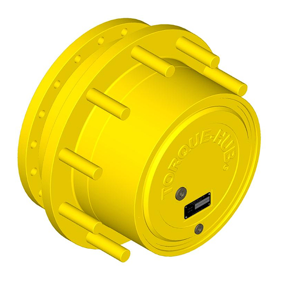
- Page 1 ® Torque-Hub Planetary Final Drive C014C5 Series Service Manual Rev 01/11/13...
- Page 2 While every precaution has been taken in the preparation of this document, Fairfield Manufacturing Co. Inc. assumes no liability with respect to the use of the documentation described herein, or for any act or omission of Fairfield Manufacturing ® Co. Inc. concerning this documentation. Torque-Hub is a registered trademark of Fairfield Manufacturing Co.
-
Page 3: Table Of Contents
Planetary Final Drive Service Manual Content Introduction Brake Test Roll and Leak Test Tightening and Torquing Bolts Lubrication Information Disassembly Instructions Main Disassembly Cover Disassembly Input Carrier Disassembly Input Brake Disassembly Input Coupling Disassembly Housing-Spindle Disassembly Output Planet Gear Disassembly Housing Disassembly Assembly Instructions Cover Subassembly... -
Page 4: Introduction
Planetary Final Drive Service Manual Introduction This manual is a step-by-step guide to the disassembly and ® assembly of the C014C5 Torque-Hub units. It is designed for the ® customer or mechanic who is repairing this particular Torque-Hub model. Users of this manual should note that each part mentioned is followed by an identification number enclosed in parentheses. -
Page 5: Brake Test
Planetary Final Drive Service Manual Brake Test The Brake Test To perform a brake check, use a M12x1.5 metric fitting. Install a hydraulic hand pump with pressure gauge into brake port in spindle (1A) using metric thread fitting. Place ROLL TEST Tool (refer to table on page 9) into input coupling. - Page 6 BRAKE CHART DIGIT FULL BRAKE NUMBER RELEASE RELEASE MAXIMUM BRAKE MODEL RELEASE PART PRESSURE PRESSURE PRESSURE TORQUE CODE PRESSURE NUMBER SPRINGS MIN (psi) MAX (psi) (psi) (in-lbs) (INPUT (psi) BRAKE) 902471 1500 5054 SPRING CHECKING PROCEDURE: UnInstall four bolts from the Adaptor Mounting in steps using an ‘X’ pattern to ensure that brake piston remains straight while being releasing compressed load out of brake cavity of spindle Carefully remove the Adaptor Mounting from the end of the input...
- Page 7 UNINSTALLING THE FOR FLAT HEX BOLTS ON ADAPTOR MONT AS THEY ARE SUBJECT TO SPRING PRESSURE Re-test the input brake. If release and/or lockup pressures still do not match the brake chart, contact the Oerlikon Fairfield service department. BRAKE LEAK REPAIR PROCEDURE: UnInstall four bolts from the Adaptor Mounting in steps using an ‘X’...
- Page 8 If brake still leaks, contact the Oerlikon Fairfield service department. Reference: Sample Model C014C5_ X _ _ _ _ _ _ _ The ‘X’ is the brake option (Model Code). Consult Oerlikon Fairfield for other brake options. NOTE: Failure to perform this test may result in damaged or ineffective brake parts.
-
Page 9: Roll And Leak Test
Planetary Final Drive Service Manual Roll and Leak Test ® Torque-Hub units should always be roll and leak tested before disassembly (if possible) and after assembly to make sure the unit’s gears, bearings and seals are working properly. The following information briefly outlines what to look for when performing these tests. - Page 10 The Leak Test The purpose of a leak test is to make sure the unit is airtight. To perform a leak test, use the leak test fixture from the table on page 10. If the tool is not available, the gearbox must be sealed to perform the test.
-
Page 11: Tightening And Torquing Bolts
Planetary Final Drive Service Manual Tightening and Torquing Bolts If an air impact wrench is used to tighten bolts, extreme care should be taken to ensure the bolts are not tightened beyond their specified torque. The following steps describe how to tighten and torque bolts or socket head cap screws in a bolt circle. -
Page 12: Lubrication Information
95 cst and maintain a minimum viscosity of 40 cst under normal operating conditions. Some applications require special considerations; consult the machine manufacturer and Oerlikon Fairfield for more additional information. The table below lists the recommended viscosities for various ambient operating temperatures. These recommendations are based on temperature rise of 50°... - Page 13 Oil temperatures should be not higher than 160° to 180°F for continuous operation, and no higher than 200°F for intermittent operation. For special applications, high horsepower, high speeds or wide temperature changes, please consult Oerlikon Fairfield. ® Oil Fill Level...
- Page 14 THIS PAGE INTENTIONALLY LEFT BLANK...
- Page 15 DISASSEMBLY...
-
Page 16: Main Disassembly
Planetary Final Drive Service Manual Main Disassembly Perform a roll check and a leak check prior to disassembling the unit. Remove the two magnetic Pipe Plugs (16 & 25) and drain the oil out of the gearbox. NOTE: Record the condition and volume of the oil. Remove the Retaining Ring (4) from the Housing. - Page 17 Remove the Input Sun Gear (6) if applicable. Remove the Input Shaft (9) from Hub-Spindle Subassembly. Lift out the Input Carrier Subassembly from Hub-Spindle Subassembly. CAUTION: Safety glasses must be worn during these next steps. UnInstall four bolts (14) from the Adaptor Mounting (12) in steps using an ‘X’ pattern to ensure that brake piston remains straight while being releasing compressed load out of brake cavity of spindle Remove the Adaptor Mounting (12) from Hub-Spindle Subassembly...
- Page 18 THIS PAGE INTENTIONALLY LEFT BLANK...
-
Page 19: Cover Disassembly
Planetary Final Drive Service Manual Cover Disassembly Remove the O-Ring (5) from groove in the Cover (2) and discard O-Ring. Remove Thrust Washers (3) from pocket in the Cover (2). This concludes the Cover Disassembly. -
Page 20: Input Carrier Disassembly
Planetary Final Drive Service Manual Input Carrier Disassembly Drive the Planet Shaft (8D) out of the carrier pin holes; forcing the Roll Pin (8E) to sheer off. Hold on to the Planet Gear (8F) and push the Planet Shaft (8D) out of the Carrier (8A). The Thrust Washers (8B) will slide off the shaft as it is removed. -
Page 21: Input Brake Disassembly
Planetary Final Drive Service Manual Input Brake Disassembly Place Hub Spindle Subassembly such that the flange side is up. CAUTION: Safety glasses must be worn during these next steps. Remove four bolts (14) from the Adaptor Mounting (12) in steps using an ‘X’ pattern to ensure that brake piston remains straight while being releasing compressed load out of brake cavity of spindle Remove the Adaptor Mounting (12) from Hub-Spindle Subassembly... - Page 22 Carefully remove the Retaining Ring (10J) from retaining groove of Spindle (1A) Remove Plastic Plug (19) from Spindle (1A) if applicable. This concludes the Input Brake Disassembly.
-
Page 23: Input Coupling Disassembly
Planetary Final Drive Service Manual Input Coupling Disassembly CAUTION: Safety glasses must be worn during these next step. Remove Retaining Ring (21) from retaining ring groove of Coupling (11). This concludes the Input Coupling Disassembly. -
Page 24: Housing-Spindle Disassembly
Planetary Final Drive Service Manual Housing-Spindle Disassembly Set the unit on a bench so that the Spindle (1A) flange is down. Remove 15 bolts (1P) that fasten the Bearing Carrier (1M) to the Hub/Spindle Sub-Assembly NOTE: Heat may need to be applied to loosen the Loctite 263 applied during assembly. Remove the Bearing Carrier (1M) out of Housing Spindle Subassembly. - Page 25 Push the 3 Output Planet Sub-Assemblies towards the center of the Hub/Spindle Sub- Assembly as shown in image above. Pull the Hub Sub-Assembly off of the spindle. Slide each Output Planet Sub-Assembly out of the spindle window. Place each sub- assembly with its respective Planet Shaft (1N) and Shim Set (1K) so that they are matched for re-assembly Using a means of prying, remove the Main Bearing Cone (1C) from the Spindle...
-
Page 26: Output Planet Gear Disassembly
Planetary Final Drive Service Manual Output Planet Gear Disassembly Place the Output Planet Gear Sub Assembly on bench. CAUTION: Safety glasses must be worn during this next steps. Remove Output Planet Bearing Cones (1R) out of Output Planet Gear (1H). Use a soft steel rod to tap out the Output Planet Bearing Cups (1Q) from Output Planet Gear (1H). -
Page 27: Housing Disassembly
Planetary Final Drive Service Manual Housing Disassembly Remove the Lip Seal (1B) from the Housing (1G). NOTE: The seal (B) should not be reused when reassembling the unit. Using a hammer and punch drive the inboard Bearing Cup (1C) out of the Housing (1G). Be careful not to damage the counter bore in the Housing (1G). - Page 28 ASSEMBLY...
-
Page 29: Cover Subassembly
Planetary Final Drive Service Manual Cover Subassembly Grease the O-ring (5) and place it in the groove in the Cover (2). Grease the O-ring (5) and place it in the groove in the Cover (2). Place the Thrust Washer (3) into counter bore of Cover (2) using grease to hold it in place. -
Page 30: Input Carrier Subassembly
Planetary Final Drive Service Manual Input Carrier Subassembly Apply a liberal coat of grease to the bore of the Planet Gear (8F). This will enable the Needle Rollers (8C) to be held in place during assembly. Install Needle Rollers (8C) into the bore of each of the three Planet Gears (8F). NOTE: The last roller installed must be installed end wise. - Page 31 Finish pushing the Planet Shaft (8D) into the Carrier (8A) until roll pin holes of Planet Shaft and Carrier are aligned. If necessary, align roll pin holes using a 1/8” diameter punch. NOTE: The chamfer on the Roll Pin hole should be towards the roll pin hole in the Carrier. Drive the Roll Pin (8E) with Chamfered end into the roll pin hole in Carrier (8A) and into the Planet Shaft (8D) until the larger end of the Roll Pin (8E) is flush with the outside diameter of Carrier (8F).
-
Page 32: Output Planet Gear Subassembly
Planetary Final Drive Service Manual Output Planet Gear Subassembly CAUTION: Safety glasses must be worn during this next steps. Install the Retaining Ring (1L) into groove of the Planet Gear (1H) by using Retaining Ring Plier. Install the Thrust Washer (1J) into bore of the Planet Gear (1H). Install the Bearing Cups (1Q) on both side of bore of the Planet Gear (1H) by using tool T-210516. -
Page 33: Input Coupling Subassembly
Planetary Final Drive Service Manual Input Coupling Subassembly CAUTION: Safety glasses must be worn during these next steps. Install the Retaining Ring (21) into the retaining ring groove of Input Coupling (11) using retaining ring installation tool. This concludes the Input Coupling Subassembly. -
Page 34: Spindle Brake Subassembly
Planetary Final Drive Service Manual Spindle Brake Subassembly NOTE: If a new Spindle is used, insure to clean up the brake port using an air gun and make sure there are no chips inside. Place Spindle (1A) such that flange side is up. CAUTION: Safety glasses must be worn during these next steps. - Page 35 Gradually feed Back-up Ring (10E) underneath O-Ring (10D). Using a small pick, push one end of the Back-up Ring (10E) to completely seat it in the groove. This ensures that the piston will not cut the Back-up Ring (10E) during assembly. Install large Backup Ring (18H) in groove on Piston (18A).
-
Page 36: Housing Subassembly
Planetary Final Drive Service Manual Housing Subassembly Place housing (1G) cover-side up onto table. Install bearing cup (1C) with wide face down, insure cup is aligned with bore. Press cup (1C) into housing using press tool. Insure that the cup is fully seated against the bearing shoulder. Turn over the housing (1G) on the table. -
Page 37: Housing-Spindle Subassembly
Planetary Final Drive Service Manual Housing - Spindle Subassembly Using alcohol and a clean rag, wipe off bearing locations on the Housing (1G) and the Spindle (1A). Apply a thin film of P-80 thix or alcohol to the OD of the spindle seal surface. Install the Bearing Cone (1C) on to Spindle (1A) with wide side down. - Page 38 Place output planet sub-assembly into windows of spindle (1A). The output planets must have their part number facing up. Slide the planet sub to the center of the spindle. Repeat the same for the rest of output planet sub-assemblies. Lift and rotate the housing sub-assembly over the spindle (1A) so that the seal is facing down.
-
Page 39: Main Assembly
Planetary Final Drive Service Manual Main Assembly Place Hub-Spindle Subassembly, spindle flange end down. Align one Stud (22) in the Housing (1G) with the brake port in Spindle (1A). Install Input Carrier Subassembly into the Hub-Spindle Subassembly with Intermediate Sun Gear (7) facing down. - Page 40 CAUTION: Safety glasses must be worn during these next steps. Align pipe plugs (16 & 25) to the Stud (22) timed with the brake port (Refer picture below) and install Cover Subassembly (2) to Housing (1G) using Retaining Ring (4). The unit should now be leak and roll checked as per instructions on page 9 &...
-
Page 41: Assembly Drawing
Planetary Final Drive Service Manual Assembly Drawing... -
Page 42: Parts List
Planetary Final Drive Repair Instructions Parts List Number Description COUPLING RETAINING RING OUTPUT PLANET GEAR BEARING CUP BEARING CONE THRUST WASHER RETAINING RING MOUNT ADAPTOR THRUST WASHER SPINDLE FLAT HEAD HEX BOLT PRESSURE PLUG COVER MAGNETIC PIPE PLUG PLATE ID RIVET MAGNETIC PIPE PLUG SUN GEAR... - Page 43 Number Description RETAINING RING SKT-UNC BOLT O-RING STUD PLASTIC PLUG BRAKE STATOR BRAKE ROTOR BRAKE STATOR BRAKE PISTON RETAINING RING BACK UP RING O-RING O-RING RETAINING RING SPRING NOTE: * For Spring (10K) quantity, refer to the Brake Chart under Brake Test on page 6.
-
Page 44: Assembly Tools
Planetary Final Drive Repair Instructions Assembly Tools T198122 – BRAKE ASSEMBLY CONCENTRICITY... - Page 45 T179926 –ASSEMBLY PRESSING TOOL...
- Page 46 T214917 – ASSEMBLY PRESSING TOOL...
- Page 47 T215321 – SEAL PRESSING TOOL...
- Page 48 T205708 – LEAK TEST ADAPTER...
- Page 49 T219813 – BEARING CONE HEATER...
- Page 50 T219850 – STUD DRIVER...
-
Page 51: Contact Information
Planetary Final Drive Repair Instructions Contact Information With more than 90 years of experience, Fairfield Manufacturing Co. Inc. has become the largest U.S. non-captive producer of gears, custom gear assemblies, planetary final drives and related gear products. Fairfield Manufacturing Co. Inc., headquartered in Lafayette, Indiana USA, is distinguished by our extensive design, manufacturing and applications engineering capabilities. - Page 52 Oerlikon Fairfield U.S. 52 South / P.O. Box 7940 Lafayette, IN 47903 USA 765-772-4000 www.oerlikon.com/fairfield...
Need help?
Do you have a question about the Torque-Hub C014C5 Series and is the answer not in the manual?
Questions and answers