Table of Contents
Advertisement
Advertisement
Table of Contents

Summary of Contents for Biomet 3i Navigator
- Page 1 Parallel Walled Navigator System For Guided Surgery ® Procedure Manual...
-
Page 3: Table Of Contents
Table Of Contents Navigator CT Guidance: Steps to Success ........................... 1 ® Getting Started ....................................3 Introduction And Treatment Planning ............................. 4 Instrumentation Overview ................................5 Surgical Plan Overview ................................... 9 Tips And Techniques ................................... 10 Immediate Provisionalization Option ............................12 Fabrication Of A New Denture Or Partial Denture And CT Scanning Appliance ................ -
Page 4: Navigator ® Ct Guidance: Steps To Success
10. The clinician will prepare the site(s) with the case-specific surgical plan and surgical guide for implant placement with the BIOMET 3i Parallel Walled Navigator Surgical Kit. 11. The implants are placed through the surgical guide. 12. The Implant Mounts and surgical guide are removed. - Page 5 Photos courtesy of Dr. Harold Baumgarten † , Philadelphia, PA and Dr. Alan Meltzer † , Voorhees, NJ † Dr. Baumgarten and Dr. Meltzer have financial relationships with BIOMET 3i LLC resulting from speaking engagements, consulting engagements and other retained services.
-
Page 6: Getting Started
Open Architecture System ® clinicians will need to purchase CT planning software from The Parallel Walled Navigator System is designed to allow one of the planning software companies and have access clinicians to place and provisionalize BIOMET 3i Dental to a CT scanning facility. Training on how to use the CT... -
Page 7: Introduction And Treatment Planning
BIOMET 3i Implant and restorative component designs provide practitioners with a wide range of restorative During the presurgical restorative planning phase of cases options, including support for single tooth crowns, fixed... -
Page 8: Instrumentation Overview
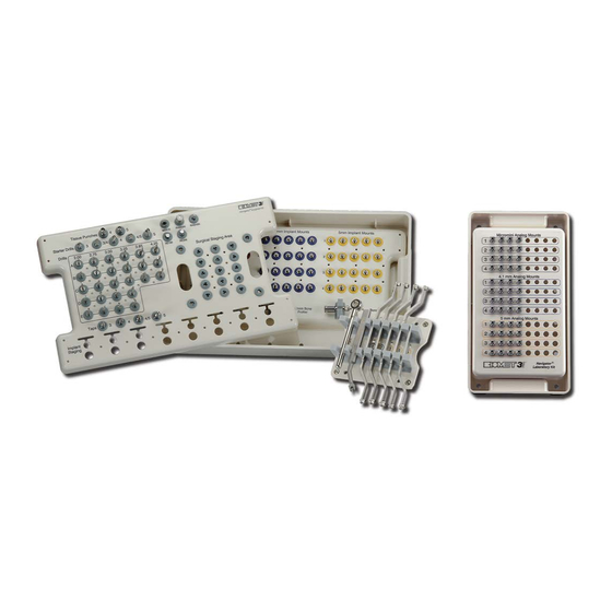
4/5/4 and straight PREVAIL 4/3 and 5/4mm Implants. With bone densities in order to plan and perform cases. Use this design, BIOMET 3i is able to support the majority of of CT scans allows procedures to be less invasive than clinical situations and compliment the use of a wide range traditional surgery. - Page 9 Implant Mounts and implants during surgery. LABORATORY KIT COMPONENTS IMPLANT ANALOG MOUNTS The Parallel Walled Navigator Laboratory Kit is comprised ® of Implant Analog Mounts used through the Master Tubes in the surgical guide to position implant analogs into a cast. The...
- Page 10 Instrumentation Overview (continued) TISSUE PUNCHES The Tissue Punches are used through the Master Tubes in the surgical guide to remove soft tissue for flapless surgery. The Tissue Punches are available in two diameters (4 and 5mm) and one length and contain depth markings of (1), (2), (3) and the top of the Tissue Punch (4) to correspond with the surgical plan (protocols) for use during surgery.
- Page 11 3.4, 4 and 5mm implants. MISCELLANEOUS TOOLS Miscellaneous standard drivers and ratchets are included in the system to place BIOMET 3i Implants. These tools include the following: PHD02N, RASH3N, MDR10, CW100, WR150 and RE100.
-
Page 12: Surgical Plan Overview
Surgical Plan Overview The Parallel Walled Navigator System For Guided ® Surgery works in conjunction with the surgical plan, which is provided by the CT planning software company. Each surgical plan is case-specific to provide direction regarding the instrumentation that will be used for each implant site. -
Page 13: Tips And Techniques
Surgical Guide. Remove the Surgical Guide and the tissue plugs. Then, replace and fixate the Surgical Guide. • Implants currently compatible with the Navigator ® System Include: • All instrumentation should be advanced as far as possible through the Master Tube(s) or the Drill Positioning •... - Page 14 Tips And Techniques (Cont’d) • Use copious irrigation on instruments prior to and during use to provide lubrication and cooling when passing through the Master Tube(s) and/or Drill Positioning Handle(s). Irrigate and suction the osteotomy and tubes to remove debris between each step of the Surgical Plan and prior to implant placement.
-
Page 15: Immediate Provisionalization Option
BIOMET 3i Implants using the Parallel Walled Navigator System For Guided Surgery. The CT software company may also offer the option of fabricating a stereo lithographic model for use in creating a master cast. -
Page 16: Fabrication Of A New Denture Or Partial Denture And Ct Scanning Appliance
Fabrication Of A New Denture Or Partial Denture And CT Scanning Appliance 1. CLINICIAN Make impressions of the maxillary and mandibular arches. 2. LABORATORY Pour the maxillary and mandibular impressions in die stone. Fabricate baseplate(s) and wax occlusal rim(s) on the cast(s). 3. - Page 17 Fabrication Of A New Denture Or Partial Denture And CT Scanning Appliance (continued) 5. CLINICIAN Place the wax try-in(s) in the mouth. Verify the occlusion, aesthetics and phonetics. Make any adjustments necessary. If major adjust- ments are necessary, make a new interocclusal registration and return to the laboratory for a new set-up and wax try-in.
-
Page 18: Fabrication Of Ct Scanning Appliance Using An Existing Denture
Fabrication Of CT Scanning Appliance Using An Existing Denture (continued) 1. CLINICIAN OR LABORATORY Using a denture duplication flask, mix the duplication material and place it into one side of the flask. Place the patient’s existing denture into the material with the soft-tissue side down. Allow the duplication material to set per the manufacturer’s instructions. -
Page 19: Pre-Surgical Fabrication Of An Edentulous Fixed Provisional Restoration
Pre-Surgical Fabrication Of An Edentulous Fixed Provisional Restoration Fabrication Of Master Cast, Articulation And Vacuum Formed Template 1. LABORATORY Select the proper diameter and length Analog Mounts for each implant position following the instructions provided by the Surgical Guide manufacturer. Place the Implant Analogs onto the Analog Mounts, line up the hexes and thread the thumb screws into these approximately two turns. -
Page 20: Pre-Surgical Fabrication Of A Partially Edentulous Fixed Provisional Restoration
Pre-Surgical Fabrication Of A Partially Edentulous Fixed Provisional Restoration Fabrication Of Master Cast, Articulation And Vacuum Formed Template 1. LABORATORY Select the proper diameter and length Analog Mounts for each implant position following the instructions provided by the Surgical Guide manufacturer. Place the Implant Analogs onto the Analog Mounts, line up the hexes and thread the thumb screws into these approximately two turns. -
Page 21: Cement-Retained Preformance ® Post
Cement-Retained PreFormance Post ® Continued from Laboratory Procedure (Steps 1-4) on page 17. ABUTMENT SELECTION Measure the soft-tissue depth in the interproximal areas at each location and select the proper abutment collar height that will allow the margin to be at soft-tissue level or slightly below after preparation. - Page 22 Cement-Retained PreFormance Post ® (continued) Remove the template from the PreFormance Posts. Remove the provisional restoration from the template. Remove all excess acrylic resin from around the margin areas and fill in any voids. Finish the restoration to the desired contour and polish.
-
Page 23: Cement-Retained Provide ® Abutment And Temporary Cylinder
Cement-Retained Provide Abutment ® And Temporary Cylinder Continued from Laboratory Procedure (Steps 1-4) on page 17. ABUTMENT SELECTION Select the proper Provide Abutment collar height for each implant by measuring the soft-tissue depth on the buccal side at each position. If a 1mm subgingival margin is desired, subtract 1mm. - Page 24 Cement-Retained Provide Abutment And ® Temporary Cylinder (continued) Remove the template from the Provide Abutments with the temporary cylinders inside the acrylic resin. Remove the provisional restoration from the template. Remove the temporary cylinders from the provisional restoration. Remove all excess acrylic resin from around the margin areas and fill in any voids.
-
Page 25: Screw-Retained Low Profile Abutment And Temporary Cylinder
Screw-Retained Low Profile Abutment And Temporary Cylinder Continued from Laboratory Procedure (Steps 1-4) on page 16. ABUTMENT SELECTION Select the proper Low Profile Abutment collar height for each implant by measuring the soft-tissue depth on the buccal side at each location. If a 1mm subgingival margin is desired, subtract 1mm. - Page 26 Screw-Retained Low Profile Abutment And Temporary Cylinder (continued) Clear the cylinder screw access opening and remove the retaining screw from the selected cylinder. Remove the template from the cast over the non-processed cylinders with the selected temporary cylinder inside the acrylic resin. Remove the provisional restoration from the template. Remove all excess acrylic resin from around the margin areas and fill in any voids.
-
Page 27: Screw-Retained Preformance Temporary Cylinder
Screw-Retained PreFormance Temporary Cylinder ® Continued from Laboratory Procedure (Steps 1-4) on page 16. ABUTMENT SELECTION PreFormance Temporary Cylinders are designed for allow acrylic resin to be added to develop the desired subgingival and supragingival contour to the restoration. The hexed cylinder is used for single-units and the non-hexed cylinder is used for multiple-unit provisional restorations. - Page 28 Screw-Retained PreFormance Temporary Cylinder ® (continued) CT GUIDED SURGICAL IMPLANT PLACEMENT 9. CLINICIAN Place the implants using a Surgical Guide and following the Surgical Guide instructions provided by the guide manufacturer. See page 9 for an example of a surgical plan. POST SURGICAL DELIVERY OF PROVISIONAL RESTORATION Place a PreFormance Temporary Cylinder on the implant...
-
Page 29: Combination Cement / Screw-Retained Quickbridge ® Restoration And Low Profile Temporary Cylinder Multiple-Unit Only
Combination Cement / Screw-Retained QuickBridge Restoration And Low Profile ® Temporary Cylinder Multiple-Unit Only Continued from Laboratory Procedure (Steps 1-4) on page 16. ABUTMENT SELECTION Select the proper Low Profile Abutment collar height for each implant by measuring the soft-tissue depth on the buccal side at each position. If a 1mm subgingival margin is desired, subtract 1mm. - Page 30 Combination Cement / Screw-Retained QuickBridge Restoration And Low Profile ® Temporary Cylinder Multiple-Unit Only (continued) Clear the cylinder screw access opening and remove the Low Profile Retaining Screw from the selected Low Profile Temporary Cylinder. Remove the template from the cast over the remaining cylinder and the Low Profile QuickBridge Caps with the Low Profile Temporary Cylinder inside the acrylic resin.
- Page 31 Combination Cement / Screw-Retained QuickBridge Restoration And Low Profile ® T emporary Cylinder Multiple-Unit Only (continued) If a flap procedure was used during surgery, suture the soft- tissue around the Low Profile Abutments. Place acrylic resin into the retention facets on the temporary cylinder and into the cylinder area on the provisional restoration.
- Page 32 Certain, Gold-Tite, Navigator, OSSEOTITE XP, PreFormance, PREVAIL, Provide and QuickBridge are registered trademarks of BIOMET 3i LLC. Providing Solutions - One Patient At A Time is a trademark of BIOMET 3i LLC. ©2016 BIOMET 3i LLC. All trademarks herein are the property of BIOMET 3i LLC unless otherwise indicated. This material is intended for clinicians or laboratories only and is NOT intended for patient distribution.
Need help?
Do you have a question about the Navigator and is the answer not in the manual?
Questions and answers