Table of Contents
Advertisement
Advertisement
Table of Contents

Summary of Contents for drexel und weiss aerosmart Series
- Page 1 aerosmart S / M / L Operating, Maintenance and Commissioning...
-
Page 3: Table Of Contents
Contents Technical Data __________________________________________________________ 2 Customer Information ____________________________________________________ 3 Product Description ......................3 Proper Application......................3 Unsuitable Applications...................... 3 Safety Instructions ......................3 Operation _____________________________________________________________ 4 Micro-Processor Controller ....................4 Main Display ........................5 Operating Modes ....................... 5 Switching On........................5 Switching Off ........................ -
Page 4: Technical Data
Technical Data General Data Mains supply ..................230 VAC / 50 Hz Recommended pre-fuse for the mains cable 1 ............16 A Recommended pre-fuse for the mains cable 2 ............13 A Heat recovery level according to VDI 2071 with nominal volumetric fl ow ..........85 % Average heat provision level of the ventilation module .........85–93 % Maximum power consumption of the fans (total) .......... -
Page 5: Customer Information
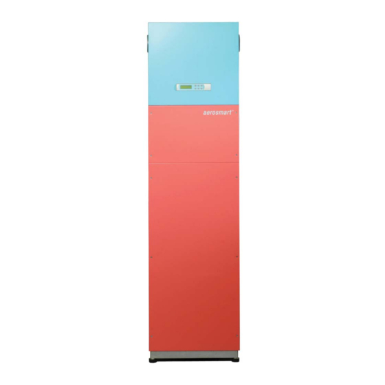
Please pay attention to the safety instructions! Product Description The devices in the aerosmart series are compact units which consist of a ventilation module with heat recovery, a domestic water storage tank and a heat pump. The unit is used to heat the supply air and the domestic water. -
Page 6: Operation
Operation The unit is controlled, managed and operated via a micro-processor controller on the unit and a room operating panel. Two types of room operating panels are available: • Analogue room operating panel with heating mode • Digital room operating panel If the analogue room operating panel is used, the basic settings must be made on the compact unit (micro-processor controller) during commissioning. -
Page 7: Main Display
Main Display The main display shows the time and date, the current operating mode and the current values for the room, set-point and actual temperature. 12:11 DI. 09/12/03 AUTOMATIK Akt. Sollwert: 21.5°C Akt. Raumtemp.: 20.3°C If you are viewing a different menu page, simply press the 'Esc' button one or more times to return to this main display. -
Page 8: Analogue Room Operating Panel With Heating Mode
Analogue Room Operating Panel with Heating Mode Use this room operating panel to set the room temperature and activate the special 'Party' mode. The LED indicator lights show if the heating is activated and if a fi lter change or fault is pending. - Page 9 A handy hint for greater system effi ciency If possible, fi nd your desired temperature at the start of the heating period. The system works most effi ciently if the set-point temperature is set once and then left unchanged. Regularly changing this setting uses the top up heater in the room more than necessary.
-
Page 10: Digital Room Operating Panel
Digital Room Operating Panel The digital room operating panel on the ventilation device operates at the same time as the micro-processor controller. The menu navigation, buttons and scope of operation are identical. Setting the Room Temperature Press the 'ESC' button until the main display appears. 12:11 DI. - Page 11 Special 'Party' Mode The ventilation is set to fan level 3 for a specifi c period. Once this period has passed, the fan level automatically returns to the currently set level. On delivery of the system, the default period is 60 minutes, but this can be adjusted in the technician level. Press 'Esc' to go from the main display to the main menu.
-
Page 12: Maintenance
Maintenance System maintenance by users is mainly limited to regularly changing the coarse particle fi lters in the ventilation module and the fi ne particle air fi lter in the outside air unit. The operating unit provides regular fi lter change notifi cations as the system operating hours are counted in the background. - Page 13 Remove the dirty fi lter pads. Insert new fi lter pads and push the cartridges back into the openings. Take care with the insertion direction! Ensure that airtightness is guaranteed. Reattach the inspection cover. Ensure that the cover is properly locked in place. (Contact switch on the control unit must be activated).
-
Page 14: Changing The Fine Particle Air Filter
Changing the Fine Particle Air Filter The fi ne particle air fi lter is located in the outside air unit and not in the compact unit. De- pending on the composition of the ventilation system, numerous fi lter types can be used. If the error message 'Change fi... -
Page 15: Commissioning
The initial commission- ing may only be carried out by technicians authorised by drexel und weiss. When the controller is powered on for the fi rst time, the controller initially performs a self- test. -
Page 16: Menu Levels
Menu levels The individual software areas are divided into levels. Press the 'Esc' button to access the main menu with the following submenus: Status Level Statusebene Technikerebene Technician Level Herstellerebene Manufacturer Level Übersicht Overview Use the arrow keys to select a sub-menu. Press 'Enter' to confi... - Page 17 Anf. Heizstab Current status of the (optional) immersion heating element in the boiler Boilergrenztemp. Überwachung The boiler is monitored for overheating. Temperature above 68°C = level 1; temperature above 73°C = level 2 (see error messages Übertemperatur Boiler WP aus - Excess tem- perature boiler heat pump off Aktuelle Stufe...
-
Page 18: Technician Level - Setting Operating Parameters
Technician Level - Setting Operating Parameters All operation-related settings are made in the technician level. Use the arrow buttons to scroll through the individual parameters on the menu pages. The cursor always fl ashes on the value to be amended. Statusebene Technikerebene Herstellerebene... - Page 19 Setting the Default Set-Point Room Temperature Stnd. Sollwert: 21.5°C Standard set-point temperature Akt. Sollwert: 20.3°C Set-point temperature Nachtabsenkung: 0.0°C Reduced set-point temperature Von/Bis: 22:00/06:00 From/ To: Stnd. Sollwert When using the analogue room operating panel, the user can turn the dial to adjust the room set-point temperature by +/- 3°C.
- Page 20 <TECHNIKEREBENE> Technician Level Sperre Raumheizung Room Heating cut-off Soll: 35°C Diff: 07.0°C Difference Soll By increasing the set-point, the warm water comfort can be increased. Diff The 'Difference' value describes the hysteresis, the exceeding of which deactivates the room heating cut-off. Setting the Nominal Air Quantities <TECHNIKEREBENE>...
- Page 21 Setting the Time and Date Set clock Uhr neu einstellen Zeit: 00:00 Time: Datum: 01/01/00 Date: day/month/year Wochentag: SO. Weekday: This window can be used to set the time and date. MO. = Monday DI. = Tuesday MI. = Wednesday DO.
- Page 22 Operating Hours Counter For control, service and maintenance purposes, various operating hours for individual operations can be viewed here. J = Yes N = No <BETRIEBSSTUNDEN> Operating Hours VERDICHTER Compressor Sum: 00000 hours Summe: 00000 STD. Reset: N Reset: No <BETRIEBSSTUNDEN>...
-
Page 23: Manufacturer Level - Factory Settings
Manufacturer Level - Factory Settings Statusebene Technikerebene Herstellerebene Übersicht This menu can be used to set the factory parameters. If needs be, these parameters can be changed by the authorised customer service agents. A password is therefore required to access the menu. Overview –... -
Page 24: Faults
Faults Error Messages The messages described here are displayed on both the micro-processor controller and the digital room operating panel. The faults cannot be acknowledged until they have been resolved. If several faults occur simultaneously, use the up and down arrow buttons '↑' '↓'... -
Page 25: Faults In The Ventilation System
or no text in the digital room operating panel No Link ( Fault with addressing the digital room operating panel; the digital room operating panel is already correctly addressed on delivery. It is, however, possible that the message 'No link' appears after commissioning or changing the room operating panel. -
Page 26: Important Unit Information (Logbook)
Important Unit Information (Logbook) Your authorised technician has handed over the unit to you with the following settings. Please keep this data handy in case of queries. Customer: Location: Unit type / version: Serial number: Initially commissioned on: Installation com- pany: Authorised technician:... - Page 27 aerosmart - Operation, Maintenance and Commissioning Page 25...
- Page 28 Legal notice Publisher: drexel und weiss energieeffi ziente haustechniksysteme gmbh. Achstrasse 42, 6922 Wolfurt T 05574 47895-0 F 05574 47895-4 E-mail: offi ce@drexel-weiss.at www.drexel-weiss.at ATU 35542007; FN 192604t; Company Accounts Registrar: Feldkirch Document number: 20080908.01 BWI-EN...
Need help?
Do you have a question about the aerosmart Series and is the answer not in the manual?
Questions and answers