
Summary of Contents for GTS iMAPLA series
- Page 1 Modular energy supply system for load lifting magnets iMAPLA 8, iMAPLA 13, iMAPLA 17, iMAPLA 20, iMAPLA 25, iMAPLA 30 Installation and operating manual English 08/2013 Issue 08/2013...
-
Page 2: Legend, Safety Instructions
Legend, safety instructions Legend, safety instructions This operating manual contains information you must observe for your own personal safety and to prevent material or property damage. The information concerning your own personal safety is emphasised with a warning triangle. Information about material or property damage without personal injury appears without a warning triangle. -
Page 3: Table Of Contents
Dimensions of the systems Technical data 4.9.1 Construction type “One Unit” 4.9.2 Construction type “External Unit” 4.10 GTS type designation and identification 4.10.1 Rating plate, generator 4.10.2 Serial number switch box / controller 4.10.3 Serial number, MMI control unit Issue 08/2013 Page 3... - Page 4 Assembly instructions for flange mount SAE5 5.6.7 Assembly instructions for hydraulic drive Arrangement of the hydraulic drive 5.7.1 Calculation for hydro-drive for GTS iMAPLA generators Installation of the switch box, construction type “External Unit” 5.8.1 Requirements on the installation position 5.8.2 Permissible installation site for a switch box 5.8.3...
- Page 5 Legend, safety instructions Contents 6.10 Troubleshooting 6.10.1 Interruption 6.10.2 Interface fault 6.10.3 Overload limitation 6.10.4 System fault 6.10.5 Underspeed 6.10.6 Overspeed 6.10.7 Insulation faults arose 6.10.8 Overtemperature pre-warning (control electronics) 6.10.9 Temperature limit exceeded (control electronics) 6.10.10 Insulation monitor faulty 6.10.11 Cyclic duration factor greater than or equal to 80 % 6.10.12 MMI overview display values 6.10.13 Troubleshooting, system fault blink codes...
-
Page 6: Important Information And Notes
The iMAPLA system is designed for use as a permanently installed power generation system in excavators or material folding machine. y The GTS iMAPLA system is only for use for suitable lifting magnets with suitable rated voltage. Always follow the manufacturer's instructions from the supplier of the lifting magnet and their safety instructions. -
Page 7: Validity Of The Manual
Important information and notes y The GTS iMAPLA system is also available as a single-bearing variant upon request. Normally they are connected directly to combustion engines. When used in this way, the manufacturer must be consulted on the suitability for use and the drive design. -
Page 8: Copyright
We are more than happy to provide information, assistance, service and ordering assistance. Generator. Technik. Systeme. GmbH & Co. KG Ziegelfeldstraße 62 + 65 73563 Mögglingen (Germany) Tel +49 (0) 7174 8 98 00-0 Fax +49 (0) 7174 8 98 00-25 www.gts-generator.com info@gts-generator.com Page 8 Issue 08/2013... - Page 9 Generator. Technik. Systeme. GmbH & Co. KG is a technically leading manufacturer of power generation systems and produces generators from 4 to 40 kVA and electronic control units of its own design. GTS generators are highly durable and of the highest quality. They are maintenance-free, long-lasting, precise and robust.
-
Page 10: Safety Instructions
Safety instructions Safety instructions The generally valid safety instructions are included in this chapter. Before the installation, commissioning and use of the iMAPLA system read this operating manual completely and carefully, and follow the instructions herein. This safety instructions also appears in the relevant areas of the text in the manual. - Page 11 Safety instructions Danger Danger to life through electric shock Insulation monitors can mutually influence each other. Do not connect any other insulation monitors to the ► iMAPLA system. Danger Danger to life through electric shock With an insulation fault, the “electrical separation” protective measure - which is otherwise provided by the system - is no longer effective.
- Page 12 Safety instructions Danger Danger to life through falling loads! A loss of drive power always leads to the uncontrolled release of the lifted load from the lifting magnet. The machine operator must check that there is sufficient ► drive power, and establish the operational reliability of the drive before commissioning.
- Page 13 Safety instructions Warning Risk of injury and risk of damage! Shutting off the drive motor counts as a general EMERGENCY STOP function. In the event of an emergency, shutting down the drive ► machine can switch off the system safely. After the shut-down, hazardous voltages may remain in and on the system for up to a max.
- Page 14 Safety instructions Warning Risk of accident An energised lifting magnet suspended in the air can attract unwanted material to it. Never switch on the lifting magnet when it is not needed ► for the work. Warning Danger to life caused by electric shock and risk of damage. Water from a high-pressure cleaner can cause damage to the iMAPLA system or electric shock.
- Page 15 Safety instructions Important The iMAPLA system is not suited for supplying fixed distribution systems. The iMAPLA system is designed for a specific output and speed. The system can be damaged by voltage peaks and overloads. The iMAPLA system must not be used for supplying ►...
- Page 16 Safety instructions Important No modifications may be made to the system or individual components of the system. Any modification, incorrect repair or use of unsuitable third party parts shall cause all warranty claims to lapse and the lapsing of the type approval according to the Equipment Safety Act (GSG) and the certification according to EU-/EEC directives.
-
Page 17: References To Standards And Directives
References to standards and directives References to standards and directives The generator has been manufactured in accordance with the following norms and directives. y DIN EN 60034 Part 1-9, rotating electrical machines y DIN EN 60204-1; VDE 0113-1:2011-01 Safety of machinery - Electrical equipment of machines: general requirements y DIN VDE 0100 (VDE 0100) Regulations for the installation of electrical power installations with rated voltages of up to 1,000 V in particular:... - Page 18 References to standards and directives y DIN EN 60204-32; VDE 0113-32:2009-03 Safety of machinery - Electrical equipment of machines-Part 32: requirements for lifting gear (IEC 60204-32:2008) y DIN EN 13155 Cranes - Safety - Non-fixed load lifting attachments (not for mobile material handling machines) y DIN EN 60068-2-27;...
-
Page 19: Imapla System Description
iMAPLA system description Components iMAPLA system description Components y Generator y Switch box with control electronics y MMI control device (Man-Machine Interface) System overview The iMAPLA system is a modular system for power generation for lifting magnets and is engineered for used in excavators. Construction type “One Unit”... - Page 20 System overview Controller with CAN Bus The controller for the iMAPLA series 2013 offers an additional CAN Bus connection which can be programed according to Standard J1939 specific to the application. It is possible to establish a direct connection to the machine controller without the MMI.
-
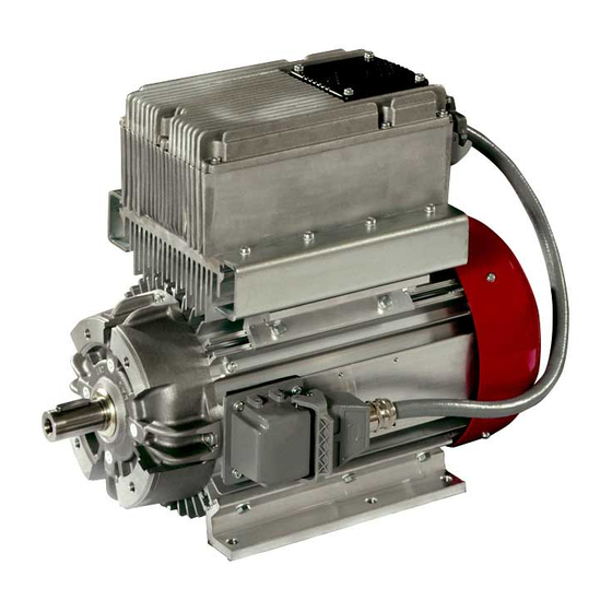
Page 21: Fig. 1. Imapla System Overview (Shown: Imapla 17 "One Unit" With Stand-Alone-Mmi)
iMAPLA system description System overview Manual control unit with control button (joystick) or footswitch upon request MMI control device Possible options: Switch box - Stand-Alone version (shown) - Radio modem Drive - Inboard version Possible options: - Sorting function (MSF) - Belt drive (shown) - Direct drive - Direct flange... -
Page 22: Special Properties
Standard J1939. It is possible to establish a direct connection to the machine controller without the MMI. Contact the particular manufacturer for the specification (Option from iMAPLA series 2013 and later for all performance categories). Page 22 Issue 08/2013... -
Page 23: Function Description
iMAPLA system description Function description Function description 4.4.1 Lift load (switch on lifting magnet) After pressing the button (Joystick S1) on the MMI manual control unit, the generator sends a voltage out to magnetise the lifting magnet. When switched on for the first time after a system start, the current that flows through the lifting magnet will increase relatively slowly, exponentially, until the rated current is reached. -
Page 24: Release Load (Switch Off Lifting Magnet)
iMAPLA system description Function description Magnetisation is completed a lot earlier and the lifting magnet reaches its maximum tension force much earlier. Once the saved current value has been reached, the voltage is reduced to the rated value. As a result, the current in the lifting magnet remains constant until the load is released. -
Page 25: Fig. 3 Characteristic Curve "Release
iMAPLA system description Function description The iMAPLA system transmits an opposite voltage (negative nominal voltage) after the “release” command until the current in the lifting magnet is zero (“demagnetisation with countervoltage”). The lifting magnet still has a residual magnetism until the current reaches zero. -
Page 26: Overload Protection Imapla
iMAPLA system description Function description 4.4.3 Overload protection iMAPLA The intelligent MAPLA system (iMAPLA system) has a sophisticated protection system which provides secure protection to the machine, generator control electronics, load cables and plug connection components against overcurrent caused by faults or excessive magnetic loads. Magnetic voltage standard overloaded system... - Page 27 iMAPLA system description Function description If the overload constraint is active, this is signalled to the machine driver on the MMI control unit. Ö MMI operating- and fault displays, page 99 Newer MMI versions do not display the overload notification until the overload values are unmistakable (>110 % of the generator's rated power).
-
Page 28: Generator Drive Types
iMAPLA system description Generator drive types Generator drive types The iMAPLA generator can be driven in different ways. Installation and required components depend on the drive type Ö Generator installation for iMAPLA 8, 13, 17 and 20, page 69 Ö Generator installation for iMAPLA 25 and 30, page 79 4.5.1 Drive via belt pulley The generator is joined to the drive unit via a belt pulley and a belt. -
Page 29: Mmi Control Unit (Stand-Alone Version)
iMAPLA system description MMI control unit (stand-alone version) MMI control unit (stand-alone version) Note The information in this chapter only applies for the stand-alone version of the standard MMI. Ö Options and accessories, page 147 4.6.1 General MMI control device (MMI = Man-Machine-Interface) The MMI control device intelligently controls all system functions and indicates the operating states. -
Page 30: Mmi Displays
iMAPLA system description MMI control unit (stand-alone version) 4.6.2 MMI displays The MMI control unit indicates all operating and fault states in the iMALPA system using LEDs. Socket for the connection cables to the iMAPLA generator Fig. 5 MMI control unit (stand-alone) and MMI displays flashing Operation indicator, MMI Operation indicator, lifting magnet (lift) -
Page 31: Mmi Plug Connections (Default Assignment)
iMAPLA system description MMI control unit (stand-alone version) Description of the individual displays Ö MMI operating- and fault displays, page 99 Summary of display values and fault blank codes for error localisation in the event of a system fault Ö System fault, page 121 Ö... -
Page 32: Installation
iMAPLA system description MMI control unit (stand-alone version) 4.6.4 Installation The MMI is installed inside the cab within the driver's field of vision to allow him / her to monitor the indicated operating states. > Either screw on with 4 screws or secure with the aid of a permanently magnetised plate affixed to the reverse side. -
Page 33: Generator And Controller
Generator and controller Generator and controller Switch boxes with control electronics (completely cast) iMAPLA: generator controller iMAPLA series 2013: insulation monitor (fully cast) Connection for MMI (RS232 interface) Connection for lifting magnet Cooling element for the switch box Cooling air inlet... -
Page 34: Fig. 10 Generator Imapla 25 "External Unit" (Example)
iMAPLA system description Generator and controller Switch box with control electronics and generator controller Connection for generator Connection for MMI (RS232 interface) Connection for lifting magnet Cooling element Connection cable for the switch box Fan wheel cover with the cooling air inlet Drain hole for condensate water Attachment bracket (both sides) Drive shaft... -
Page 35: Description
iMAPLA system description Generator and controller 4.7.1 Description The generator is a brush-less, electronically controlled synchronous generator which is designed for continuous operation and is very speed-tolerant. As a result, it has a high service life, is maintenance-free and very free of interference. The ball bearings used in the generator are maintenance-free. - Page 36 (rotational frequencies). The generator controller does not need a separate current supply, as it is supplied by the generator. From iMAPLA series 2013 and later, the generator controller is integrated on the Powerboard. This allows for generator variables to be controlled more efficiently and safely.
-
Page 37: Plug Connections On The Generator And Switch Box
iMAPLA system description Generator and controller 4.7.2 Plug connections on the generator and switch box The connector assignment for 132 (BG132) model generators each with a 2-pole assignment from 8 to 20 kW rated power: Generator Socket Cable (s) or Switch box connection on connection to the generator the switch box... -
Page 38: Fig. 12 Imapla 25 And 30; Plug Connection Generator-Switch Box
iMAPLA system description Generator and controller The connector assignment for 160 (BG160) model generators each with a 4-pole assignment with a rated power >=25 kW: Generator Socket on Cable for Switch box generator Switch box Housing weight Housing weight Generator U1 Generator U1 Generator U2 Generator U2 Generator V1... -
Page 39: Fig. 14. Connection Assignment At The Lifting Magnet Output, Imapla 8 To Imapla 20
Generator and controller The MMI interface is standardised by GTS on all switch boxes and is backwards-compatible. An old MMI and the system tester can be connected to the MAPLA, iMAPLA and the new iMAPLA 2013 series. Warning... -
Page 40: Fig. 15. Connection Assignment At The Lifting Magnet Output Imapla 25 And 30
iMAPLA system description Generator and controller Load cable (s) to the magnet Lifting magnet black Gray brown blue gn/ge Fig. 15 Connection assignment at the lifting magnet output iMAPLA 25 and 30 Page 40 Issue 08/2013... -
Page 41: Fig. 16 Connection Assignment Can Socket Imapla 2013 Series
iMAPLA system description Generator and controller brown CAN-GND (shielding) white CAN Low blue CAN High black MMI-GND Output gray MMI +15 V Output Fig. 16 Connection assignment CAN socket iMAPLA 2013 series Information about the CAN connection y From the iMAPLA 2013 series, a CAN Bus connection is also provided alongside the MMI interface. -
Page 42: Dimensions Of The Systems
iMAPLA system description Dimensions of the systems Dimensions of the systems Fig. 17 Dimensioned drawing iMAPLA 8 “One Unit” Page 42 Issue 08/2013... -
Page 43: Fig. 18 Dimensioned Drawing Imapla 8 "External Unit
iMAPLA system description Dimensions of the systems Fig. 18 Dimensioned drawing iMAPLA 8 “External Unit” Issue 08/2013 Page 43... -
Page 44: Fig. 19 Dimensioned Drawing Imapla 13 "One Unit
iMAPLA system description Dimensions of the systems Fig. 19 Dimensioned drawing iMAPLA 13 “One Unit” Page 44 Issue 08/2013... -
Page 45: Fig. 20 Dimensioned Drawing Imapla 13 "External Unit
iMAPLA system description Dimensions of the systems Fig. 20 Dimensioned drawing iMAPLA 13 “External Unit” Issue 08/2013 Page 45... -
Page 46: Fig. 21 Dimensioned Drawing Imapla 17 "One Unit
iMAPLA system description Dimensions of the systems Fig. 21 Dimensioned drawing iMAPLA 17 “One Unit” Page 46 Issue 08/2013... -
Page 47: Fig. 22 Dimensioned Drawing Imapla 17 "External Unit
iMAPLA system description Dimensions of the systems Fig. 22 Dimensioned drawing iMAPLA 17 “External Unit” Issue 08/2013 Page 47... -
Page 48: Fig. 23 Dimensioned Drawing Imapla 25 "External Unit
iMAPLA system description Dimensions of the systems Fig. 23 Dimensioned drawing iMAPLA 25 “External Unit” Page 48 Issue 08/2013... -
Page 49: Fig. 24. Dimensioned Drawing Imapla 20
iMAPLA system description Dimensions of the systems 528.5 10.5 Fig. 24 Dimensioned drawing iMAPLA 20 Issue 08/2013 Page 49... -
Page 50: Fig. 25 Dimensioned Drawing Imapla 30 "One Unit
iMAPLA system description Dimensions of the systems Fig. 25 Dimensioned drawing iMAPLA 30 "One Unit Page 50 Issue 08/2013... -
Page 51: Technical Data
iMAPLA system description Technical data Technical data 4.9.1 Construction type “One Unit” iMAPLA iMAPLA iMAPLA iMAPLA iMAPLA 25/30 Generator principle Brushless electronic controlled synchronised generator (three-phase winding) Nominal output 8 kW 13 kW 17 kW 20 kW 25/30 kW Nominal voltage 230 V Surge voltage 280 V Rated current 34.7 A 56.5 A... -
Page 52: Construction Type "External Unit
iMAPLA system description Technical data 4.9.2 Construction type “External Unit” iMAPLA iMAPLA iMAPLA iMAPLA Generator principle Brushless electronic controlled synchronised generator (three-phase winding) Nominal output 8 kW 13 kW 17 kW 25 kW Nominal voltage 230 V Surge voltage 280 V Rated current 34.7 A 56.5 A 73.9 A 108 A Permissible speed 2800 to 4500 min... -
Page 53: Gts Type Designation And Identification
GTS type designation and identification 4.10 GTS type designation and identification The GTS MAPLA and iMAPLA series has a range of possibilities for identifying the existing components and components in use. Normally, information about the generation (iMAPLA or new iMAPLA 2013 series) of the controller (switch box) is needed for analysis or for ordering spare parts. - Page 54 = old MAPLA system, predecessor to the iMAPLA xxxx generations = iMAPLA system, xxxx-INT13 position 13 indicates the power class in kW. = iMAPLA series 2013 (with CAN Bus), xxxx-I13G2 position 13 indicates the power class in kW. Page 54 Issue 08/2013...
-
Page 55: Serial Number Switch Box / Controller
1234 = Serial number of electronic controller (4 digits for iMAPLA) Ø = hardware ID, switch box (Ø = newer version, not used for iMAPLA series 2013) Serial number, iMAPLA 2013 series switch box (with CAN Bus) 12345 I13 G2 -2 ISO Uxx... - Page 56 GTS type designation and identification Danger Risk of injury and risk of damage! Using switch boxes with a higher performance class than the generator is not allowed. Risk of permanent / creeping overload / overheating of the generator. Note 2-pole and 4-pole version iMAPLA controllers are only compatible with the connectors on the appropriate generator.
-
Page 57: Serial Number, Mmi Control Unit
Possible MMI type descriptions B13 INT STD STD = version (here STD = Standard) INT = suitable for the iMAPLA series (also backwards-compatible to existing MAPLA systems) B13 = MMI with fixed power class in kW (this entry does not apply with the new MMI which is independent of the... -
Page 58: Installation And Commissioning
Installation and commissioning General safety instructions Installation and commissioning This chapter describes the installation and the commissioning of the iMAPLA system. The system may only installed by authorised and appropriately qualified technicians. Minor variations in procedures may arise depending on the MMI version. Reference is made to these deviations in the corresponding chapters of this manual. - Page 59 Installation and commissioning General safety instructions Danger Risk of injury and risk of damage! Incorrectly installing the iMAPLA system can cause malfunctions or damage, or lead to dangerous situations. Before the installation of the iMAPLA system read this ► operating manual completely and carefully, and follow the instructions herein.
- Page 60 Installation and commissioning General safety instructions Danger Danger to life through electric shock All work on the iMAPLA system, visual inspections for maintenance purposes or cleaning work during operation of the system can lead to potentially fatal injury through electric shock.
- Page 61 Installation and commissioning General safety instructions Warning Risk of injury When protective coverings are not in use, there is a risk of injury through electric shock, moving parts and hot surfaces. Only operate the iMAPLA system when protective covers ► have been fitted for the drive as specified. Warning Risk of injury and risk of damage! The use of unauthorised third party parts can lead to...
- Page 62 Installation and commissioning General safety instructions Important The iMAPLA system is not suited for supplying fixed distribution systems. The iMAPLA system is designed for a specific output and speed. The system can be damaged by voltage peaks and overloads. The iMAPLA system must not be used for supplying ►...
-
Page 63: Delivery Scope
Installation and commissioning Delivery scope Delivery scope Please verify the completeness of the delivery before installation of the system. Please get in touch with the manufacturer or the supplying agent if any parts are missing or if you have questions. Construction type “One Unit”... -
Page 64: Installation Of Mmi
Installation and commissioning Installation of MMI Construction type “External Unit” and Stand-Alone MMI y iMAPLA Generator y Switch box y MMI y Connection cable, MMI switch box y Connection cable, switch box lifting magnet y Connection cable, MMI to control button Construction type “External Unit”... -
Page 65: Pre-Assembled Cables, Supplied
Installation and commissioning Installation of cables 5.4.1 Pre-assembled cables, supplied Use the pre-assembled cables ex works which are supplied. These cables were specially selected for the requirements in such systems and carefully inspected and, therefore, offer the best-possible guarantee of a fault- and fault-free operation. -
Page 66: Rules For Cable Installation
As usual, select all connection cables in accordance with the electrical and mechanical requirements. Only use the supplied cables which were pre-assembled in the factory, or cable types expressly permitted by GTS. Minimum requirements for the cables used y UV-resistant,... - Page 67 Installation and commissioning Installation of cables Requirements for the connection cables between generator and lifting magnet Minimum cross sections y iMAPLA 8: 5 x 4 mm² Cu y iMAPLA 13: 5 x 4 mm² Cu y iMAPLA 17: 5 x 6 mm² Cu y iMAPLA 20: 5 x 6 mm² Cu y iMAPLA 25 and 30: 5 x 10 mm²...
- Page 68 Installation and commissioning Installation of cables Specifications Regulations DIN VDE 0627 DIN VDE 0110 Contact inserts Number of contacts 4 + PE Rated current max. 40 A Rated voltage 1000 V Test voltage Ueff 4 kV Contamination level 3 (C) Insulation resistance ≥ 1010 MegaOhm Material Polycarbonate Temperature range...
-
Page 69: Generator Installation For Imapla 8, 13, 17 And
Installation and commissioning Generator installation for iMAPLA 8, 13, 17 and 20 Generator installation for iMAPLA 8, 13, 17 and 20 y To install the generators, proceed according to the descriptions in this chapter. y Prior to installation, read the safety instructions attentively and follow the instructions and information therein. -
Page 70: Requirements On The Installation Position
Installation and commissioning Generator installation for iMAPLA 8, 13, 17 and 20 5.5.1 Requirements on the installation position iMAPLA Generators “One Unit” construction type with attached switch box y Do not assemble the “One Unit” type in the engine compartment. iMAPLA Generators “External Unit” construction type with a separate switch box y Do not expose the External Unit type to the radiation range of heat sources (e.g. exhaust pipes). -
Page 71: Permissible Installation Positions
Installation and commissioning Generator installation for iMAPLA 8, 13, 17 and 20 5.5.2 Permissible installation positions The generator must be monitored on a horizontal surface standing on the attachment brackets as shown. In the normal installation position, the plug attached to the generator lies on the side of the generator. -
Page 72: Minimum Clearances And Cooling Provisions
Installation and commissioning Generator installation for iMAPLA 8, 13, 17 and 20 y Secure the generator with at least four mounting screws (minimum M8 or comparable, bolt grade min. 8.8). y The attachment must be permanent and resistant to shock and vibrations. y Use suitable means to prevent the screws from coming undone by themselves, e.g. via a tension ring according to DIN 128. - Page 73 Installation and commissioning Generator installation for iMAPLA 8, 13, 17 and 20 Minimum clearances When installing, respect the following minimum clearances from fixed parts or walls Ö adjacent figures y Both sides and above: a = 100 mm y Front: w = 200 mm y Rear: c = 170 mm Temperature and pressures of the cooling air Important A cooling air feed above 40 °C can lead to power restrictions;...
-
Page 74: Assembly Instructions For Belt Drive
Installation and commissioning Generator installation for iMAPLA 8, 13, 17 and 20 5.5.5 Assembly instructions for belt drive Warning Risk of accident Open drive belts and pulleys are a hazard. Never operate the generator without ► a protective covering. Never reach into a drive belt while it is ►... - Page 75 Installation and commissioning Generator installation for iMAPLA 8, 13, 17 and 20 Important ► The drive belt must not sag loosely. When using narrow belt pulleys of type SPA, the clearance between the axes must not exceed 600 mm. For permissible axis clearances for other belts, ask the manufacturer.
-
Page 76: Assembly Instructions For Flange Mount Sae5
Installation and commissioning Generator installation for iMAPLA 8, 13, 17 and 20 5.5.6 Assembly instructions for flange mount SAE5 Preparatory disassembly Ö Fig. 27, Preparatory disassembly of the flange mount (iMAPLA 8 and 13), page 76 > Unscrew two M8 x 45 screws [2], wrench size 10 mm. >... -
Page 77: Assembly Instructions For Hydraulic Drive
Installation and commissioning Generator installation for iMAPLA 8, 13, 17 and 20 > Secure the drive side of the coupling [6] to the drive and insert it into the coupling plate. If necessary, while inserting, twist slightly until the gearing locks. > Secure the flange [1] to the drive unit. -
Page 78: Fig. 29. Assembly Of The Flange Mount For The Hydraulic Drive (Using Imapla 13 As An Example)
Installation and commissioning Generator installation for iMAPLA 8, 13, 17 and 20 Assembly Ö Fig. 29, Assembly of the flange mount for the hydraulic drive (using iMAPLA 13 as an example), page 78 > Place the flange [2] onto the generator and secure with four screws [4a]. >... - Page 79 Installation and commissioning Generator installation for iMAPLA 25 and 30 Generator installation for iMAPLA 25 and 30 y To install the generators, proceed according to the descriptions in this chapter. y Prior to installation, read the safety instructions attentively and follow the instructions and information therein.
-
Page 80: Requirements On The Installation Position
Installation and commissioning Generator installation for iMAPLA 25 and 30 5.6.1 Requirements on the installation position iMAPLA Generators “One Unit” construction type with attached switch box y Do not assemble the “One Unit” type in the engine compartment. iMAPLA Generators “External Unit” construction type with a separate switch box y Do not expose the External Unit type to the radiation range of heat sources (e.g. exhaust pipes). -
Page 81: Permissible Installation Position
Installation and commissioning Generator installation for iMAPLA 25 and 30 5.6.2 Permissible installation position The generator must be monitored on a horizontal surface standing on the attachment brackets as shown. The controller (iMAPLA 30) or terminal box (iMAPLA 25) attached to the generator must always be on top. -
Page 82: Assembly (Imapla 25 And 30)
Installation and commissioning Generator installation for iMAPLA 25 and 30 5.6.3 Assembly (iMAPLA 25 and 30) During assembly, observe the minimum clearances and specifications for cooling in the following chapter. Generator dimensions Ö Minimum clearances and cooling provisions, page 82 Secure the generator with at least four mounting screws (minimum M12 or comparable, bolt grade min. 8.8). - Page 83 Installation and commissioning Generator installation for iMAPLA 25 and 30 Minimum clearances When installing, respect the following minimum clearances from fixed parts or walls. Ö Adjacent figures y Both sides and above: a = 100 mm y Front: w = 300 mm y Rear: c = 200 mm Temperature and pressures of the cooling air Important A cooling air feed above 40 °C can lead to power restrictions;...
-
Page 84: Assembly Instructions For Belt Drive
Installation and commissioning Generator installation for iMAPLA 25 and 30 5.6.5 Assembly instructions for belt drive Warning Risk of accident Open drive belts and pulleys are a hazard. Never operate the generator without ► a protective covering. Never reach into a drive belt while it is ►... - Page 85 Installation and commissioning Generator installation for iMAPLA 25 and 30 Important ► The drive belt must not sag loosely. When using narrow belt pulleys of type SPA, the clearance between the axes must not exceed 800 mm. For permissible axis clearances for other belts, ask the manufacturer.
-
Page 86: Assembly Instructions For Flange Mount Sae5
Installation and commissioning Generator installation for iMAPLA 25 and 30 5.6.6 Assembly instructions for flange mount SAE5 Preparatory disassembly Ö Fig. 30, Preparatory disassembly of the flange mount SAE5 (iMAPLA 25 and 30), page 86 > Unscrew and remove four grub screws M12 x 20 [1]. 1(4x) Fig. -
Page 87: Assembly Instructions For Hydraulic Drive
Installation and commissioning Generator installation for iMAPLA 25 and 30 > Secure the drive side of the coupling [4] to the drive and insert it into the coupling plate. If necessary, while inserting, twist slightly until the gearing locks. > Secure the flange [1] to the drive unit. -
Page 88: Fig. 32 Assembly Of Flange Mount Hydraulic Drive (Imapla 25 And 30)
Installation and commissioning Generator installation for iMAPLA 25 and 30 Assembly Ö Fig. 32, Assembly of flange mount hydraulic drive (iMAPLA 25 and 30), page 88 > Place the flange [1] onto the generator and secure with four screws [2a]. Place a toothed washer [2b] underneath the screws and secure with Loctite. -
Page 89: Arrangement Of The Hydraulic Drive
Arrangement of the hydraulic drive Arrangement of the hydraulic drive 5.7.1 Calculation for hydro-drive for GTS iMAPLA generators These calculation principles are relevant to the use of hydraulic axial piston engines. The feed performance of the hydraulic pump can be found from the central hydraulic systems or other components, such as the hammer piping. - Page 90 Nm] Operating a GTS iMAPLA at SunFab Hydro-Motors GTS offers options in the arrangement of the hydraulic drive through the use of special flow rate control valves. The indicated working pressures and volume flows in the table are to be used using the SunFab axial piston hydraulic motors (optionally also) offered by GTS.
-
Page 92: Installation Of The Switch Box, Construction Type "External Unit
Installation and commissioning Installation of the switch box, construction type “External Unit” Installation of the switch box, construction type “External Unit” Install the switch box according to the descriptions in this chapter. Prior to installation, read the safety instructions in chapter 2 attentively and follow the instructions and information therein. Ö... -
Page 93: Permissible Installation Site For A Switch Box
Installation and commissioning Installation of the switch box, construction type “External Unit” 5.8.2 Permissible installation site for a switch box The switch box must be mounted so that the cooling vanes are vertical and to ensure unobstructed air convection through the cooling vanes. iMAPLA 8 + 13 The plug connections on the switch box must face down in the installation position. -
Page 94: Commissioning
Installation and commissioning Commissioning Commissioning CAUTION In addition to the work given here, checks on the drive system may be necessary as set out in the requirements and regulations of the drive / system manufacturer. This also contains the proper attachment of protective covers. This work must be performed by the person responsible for the machine. -
Page 95: Operation
Operation Safety instructions for operation Operation This chapter describes the operation of the iMAPLA system. Minor variations in the operating procedures may arise depending on the MMI version. Reference is made to these deviations in the corresponding chapters of this manual. - Page 96 Operation Safety instructions for operation Danger Danger to life through falling loads! A loss of drive power always leads to the uncontrolled release of the lifted load from the lifting magnet. The machine operator must check that there is sufficient ►...
- Page 97 Operation Safety instructions for operation Caution Burn hazard Parts of the iMAPLA system can get very hot during and after operation. Allow the iMAPLA-System and parts to cool down before ► touching. Important The optionally built-in insulation monitor must trip in the self-test.
-
Page 98: Operating Instructions
Operation Operating instructions Operating instructions The iMAPLA system offers the highest levels of efficiency in material handling as a result of the quick magnetisation and demagnetisation times. As a result, the time for the full magnetisation of the large lifting magnets can take up to 4 seconds. -
Page 99: Mmi Operating- And Fault Displays
Operation MMI operating- and fault displays MMI operating- and fault displays The MMI control unit indicates all operating and fault states in the iMALPA system using LEDs. Fig. 33 MMI displays flashing Operation indicator, MMI Operation indicator, lifting magnet (lift) Quick magnetisation running (release) Interruption Interface fault... - Page 100 Operation MMI operating- and fault displays LED 1 Operation indicator, MMI Green The LED is lit y Supply voltage present for MMI. The system is switched on and ready for use, the generator is running. Note: The MMI can also be powered by an external power supply. (For example on systems adapted to specific customer needs or with an MMI with radio modem).
- Page 101 Operation MMI operating- and fault displays LED 3 Quick magnetisation Yellow The LED is lit y Quick magnetisation of the lifting magnet is activated. Ö “Release” The LED lights up during quick magnetisation. The LED goes out once quick magnetisation has been fully completed.
- Page 102 Operation MMI operating- and fault displays Multi-function / assignment: The LEDs flash at the same time: insulation fault 4+5+6 Ö Insulation faults arose, page 124 LED 4+5+6 light up and 100 %-LED flashes 4+5+6 Temperature warning, control electronics Ö Temperature for control electronics exceeded LED 5 Fault indicator The LED is lit: overload limitation...
- Page 103 Operation MMI operating- and fault displays Fault indicator 6 red The LED is lit: underspeed y The generator runs at an underspeed and may not be able to provide full power under certain circumstances. When switching on, it is possible that the lifting magnet is not magnetised with full surge voltage.
- Page 104 Operation MMI operating- and fault displays LED 7 Cyclic duration factor of the lifting magnet Multi-coloured LED display (50 % green, 60 % yellow, 70 % orange, from 80 % red): y The cyclic duration factor of the lifting magnet is indicated in per cent.
- Page 105 Operation MMI operating- and fault displays Multiple functions when several LEDs light up at the same time Insulation fault indication / ISO fault occurred 4+5+6 If an insulation fault is active, a magnet restart block flashing automatically becomes active, i.e. after putting the load down, the operator is no longer able to switch the magnet back on again.
-
Page 106: Establish The System's Readiness For Use
Operation Establish the system's readiness for use Excess temperature, control electronics 4+5+6 Ö Temperature limit exceeded (control electronics), flashing page 127 & y The temperature in the control electronics has exceeded 100 % LED the permissible threshold and the system is switched off flashes immediately without further warning. -
Page 107: Daily Inspection Of The Insulation Monitor
Operation Daily inspection of the insulation monitor The MMI is not supplied with voltage by the generator (External power supply) y Switch on the voltage supply for the MMI. The green LED 1 then lights up. y Start the drive unit. >... -
Page 108: Set Operating Modes, Normal Mode And Jog Mode (Machine Handling And Sorting Operation)
Operation Note There are systems without the optional insulation monitor. Without an insulation monitor, the LED does not flash during the requested self-test. The serial number on the switch box has the letters “ISO” if an insulation monitor is installed. If “ISO” is not stamped on the switch box this means no insulation monitor is installed. -
Page 109: Jog / Sort Mode [B] (Switch Setting Below)
6.6.3 Other optional modes GTS offers a range of different MMI variants adapted to and programmed for specific applications. This can be used with every iMAPLA system and are plug-compatible. Some examples for functions upon demand: y MMI INT MSF (extended sorting and material handling) Setting magnetic force and release response. -
Page 110: Operating In Normal Or Material Handling Mode [A]
Operation Operating in Normal or Material handling mode [A] Operating in Normal or Material handling mode [A] For Normal mode, the switch on the right-hand side of the MMI must be in the top position [A] = Material handling mode = Normal mode. In Normal mode, the lifting magnet is switched on by pressing the control button briefly and remains switched on until the control button is pressed again briefly. - Page 111 Operation Operating in Normal or Material handling mode [A] Note If the control button is pressed again after switching on the lifting magnet (while magnetisation is still running), magnetisation is stopped and the automatic quick release / shut-down is started straight away. In this case, the system may require a few magnetisations until the maximum tension force of the lifting magnet becomes available.
-
Page 112: Release Load (Switch Off Lifting Magnet)
Operation Operating in Normal or Material handling mode [A] 6.7.2 Release load (switch off lifting magnet) > Move the lifting magnet with the suspended load into the position for releasing the load. > Briefly press the control button. LED 2 on the MMI goes out and the LED 3 light is out for the duration of the automatic quick magnetisation. -
Page 113: Operation In Jog Mode / Sorting Mode [B]
Operation Operation in Jog mode / Sorting mode [B] Operation in Jog mode / Sorting mode [B] Job mode The “switch is down” on the right-hand side of the MMI [B] = Sorting mode = Jog mode. The Jog mode is particularly good for separating the material. This operating mode is usually not suited to normal material handling as the lifting magnet only remains switched on for as long as the control button remains pressed. -
Page 114: Lift Load
Operation Operation in Jog mode / Sorting mode [B] 6.8.1 Lift load > Place the lifting magnet on the load to be raised. > Press the control button and keep it pressed. LED 2 lights up on the MMI. y The lifting magnet is magnetised and remains switched on until the control button is held down. -
Page 115: System Restart Imapla Controller
Operation System restart iMAPLA controller System restart iMAPLA controller In processor-controlled systems, faults may arise when processing information during processing programs. In this case, the processor system must be brought into a pre-defined home position. This is achieved via a “restart”. For certain faults, a system restart of the iMAPLA controller will be necessary. Carrying out the restart In the system, the MMI is supplied with voltage by the generator Ö... - Page 116 Operation Troubleshooting 6.10 Troubleshooting This chapter describes the system fault displays and the required measures for troubleshooting. Carefully read the safety instructions. Safety instructions for troubleshooting Danger Risk of injury and risk of damage! Opening or disassembling the iMAPLA system puts the system at risk and compromises the safety of the user.
- Page 117 Operation Troubleshooting Danger Danger to life! Strong, permanent magnetic fields can impair the operation of active implants / pacemakers. Persons with pacemakers are not allowed to remain in the ► vicinity of lifting magnets when switched on. Always maintain a sufficient safety clearance from the lifting ►...
- Page 118 Operation Troubleshooting 6.10.1 Interruption LED 4 The LED is lit: y The connection cable to the lifting magnet is not connected or the connection is broken. After switch-on, a check is run to see whether current is flowing through the lifting magnet. Without a flow of current, the lifting magnet will be switched off again after approx.
- Page 119 Operation Troubleshooting 6.10.2 Interface fault LED 4 The LED is flashing y A fault occurred on the interface between MMI and the controller. Note When using an MMI with radio modem, a fault in the radio transmission can also be the cause of the fault. Troubleshooting measures >...
- Page 120 Operation Troubleshooting 6.10.3 Overload limitation LED 5 The LED is lit: y The connected lifting magnet is too big for the iMAPLA system. The built-in overload / current limiter of the iMAPLA is active. The LED continues to light up after being switched back on. The LED will not go out until an overload state is no longer detected after the next time the lifting magnet is switched off.
- Page 121 Operation Troubleshooting 6.10.4 System fault LED 5 The LED is flashing y A critical safety fault on the iMAPLA controller occurred. (On old MAPLA systems, this fault message denotes a short circuit on the magnet output.) The output to the lifting magnet is switched off immediately. The LED goes out after a system restart.
- Page 122 Operation Troubleshooting 6.10.5 Underspeed LED 6 The LED is lit: y The generator runs at an underspeed and may not be able to provide full power under certain circumstances. When switching on, it is possible that the lifting magnet is not magnetised with full surge voltage.
- Page 123 Operation Troubleshooting 6.10.6 Overspeed LED 6 The LED is flashing y The generator is operating at an overspeed. After releasing the load, it is not possible to switch the plate back on again. The LED goes out once the speed is within the tolerance limits again.
- Page 124 Operation Troubleshooting 6.10.7 Insulation faults arose LEDs 4+5+6 flash at the same time If LEDs 4+5+6 flash at the same time when switching on or operating the machine, the built-in insulation monitor will detect an insulation fault. If this message is active, a magnet restart block is automatically active, i.e. after putting the load down, the operator is no longer able to switch the magnet on again.
- Page 125 If current systems with ISO monitors are run with faulty magnets, a fault message will arise. The letters “ISO” in the serial number stamped on the switch box / controller indicates whether an insulation monitor has been installed in your system. Ö GTS type designation and identification, page 53 Issue 08/2013 Page 125...
- Page 126 Operation Troubleshooting 6.10.8 Overtemperature pre-warning (control electronics) LED 4+5+6 light up and 100 %-LED flashes Even though the iMAPLA system is designed for continuous operation, it may become too hot. This risk exists when, under a fill load, the cooling of the generator (for “One Unit”) or the control electronics (for “External Unit”) is impaired, or when the temperature of the cooling air exceeds the maximum permissible value of 40 °C.
- Page 127 Operation Troubleshooting y Check whether the cooling air inlet and outlet openings are free and whether the cooling air can flow unimpeded through the cooling profiles of the switch box. Clean the switch box cooling profiles with a damp cloth if required. y If the fault persists, please get in touch with the manufacturer or a party authorised by the manufacturer.
- Page 128 Operation Troubleshooting Note More recent iMAPLA systems report an excess temperature as a system fault (LED 5 flashes). On newer iMAPLA systems, the control electronics will not switch off the magnet for safety reasons. Nevertheless, this message should ALWAYS be considered as a very critical operating state! 6.10.10 Insulation monitor faulty When the system is running and after pressing the check button for the...
- Page 129 Operation Troubleshooting 6.10.11 Cyclic duration factor greater than or equal to 80 % The cyclic duration factor of the lifting magnet is the ratio between the switch-on/switch-off time. A switch-on time of 1 minute and subsequent switch-off time of 1 Minute is equivalent to a relative connection time of 50)%.
- Page 130 Operation Troubleshooting 6.10.12 MMI overview display values Power category in kW (this entry is not required for new MMIs) 10 INT variant: intelligent MAPLA = iMAPLA (these three letters are not used in older versions) 11 Variant of MMI / Typ Bxx INT xxxx 1 MAPLA system is ready for use The voltage supply for the MMI is present.
- Page 131 Operation Troubleshooting 5 Overload / system fault LED on: Overload (current limiter on iMAPLA active) This LED lights up when the connected lifting magnet is too big for the iMAPLA system or a fault arose on the lifting magnet or load cable. The material handling output is reduced accordingly / the magnetic current is restricted to the machine's maximum.
- Page 132 6.10.13 Troubleshooting, system fault blink codes Blink code table of the iMAPLA (INT) MMIs when a SYSTEM FAULT (= LED No. 5 blinks) is displayed. Valid for MMIs with label: “INT” and suitable iMAPLA controller. LED No. 5 is flashing= SYSTEM FAULT (Magnet re-engaging lock active) By pressing the joystick button (for 5 secs.) a fault blink code is indicated on the 100 % ED LED.
- Page 133 = 3 x brief ON = 3 x brief ON Example for blink code no. 3: LED ON (LED flashes three LED OFF times Time Pause LED OFF Count value = Code 3) Note: On the iMAPLA 2013 series, the description of blink codes 8 to 10 is different.
- Page 134 Maintenance and care Troubleshooting Maintenance and care All system components are in principal maintenance-free. However, carry out the maintenance activities listed by the user in the maintenance overview in the Visual checks / cleaning work chapter regularly and timely in order to ensure reliable operation of the system.
- Page 135 Maintenance and care Safety instructions Safety instructions This chapter summarises the safety instructions relevant for the maintenance work. Danger Risk of injury and risk of damage! Opening or disassembling the iMAPLA system puts the system at risk and compromises the safety of the user.
- Page 136 Maintenance and care Safety instructions Danger Danger to life! Strong, permanent magnetic fields can impair the operation of active implants / pacemakers. Persons with pacemakers are not allowed to remain in the ► vicinity of lifting magnets when switched on. Always maintain a sufficient safety clearance from the lifting ►...
- Page 137 Maintenance and care Safety instructions Warning Risk of injury and risk of damage! During maintenance, make sure that the PE/PA connection (potential connection, usually green / yellow) between the lifting magnet and generator controller is connected to the electricity supply. Without this, the detection of external ISO faults in the lifting magnet will not be possible.
- Page 138 Maintenance and care Visual inspection / cleaning work by the user Visual inspection / cleaning work by the user Read and follow the safety instructions in the Safety instructions chapter as well as the information given here. Ö Safety instructions, page 135 Danger Danger to life through electric shock Never carry out visual inspections on the iMAPLA system for maintenance purposes and cleaning during operation.
- Page 139 Maintenance and care Visual inspection / cleaning work by the user Cables Check the junction cables and plug connections. y between generator and switch boxes, y between switch box and the lifting magnet, y between switch box and MMI (for MMI with radio modem: between switch box and radio modem) and y between MMI and manual control unit (joystick) y for outwardly visible damage and correct fit of the plugs.
- Page 140 Maintenance and care Maintenance work carried out by authorised personnel Maintenance work carried out by authorised personnel Warning Risk of injury and risk of damage! When working on the iMAPLA system, insufficiently qualified persons put themselves at risk and can damage the system. The assembly, connection and commissioning of the ►...
- Page 141 Repairs / repair Maintenance work carried out by authorised personnel Repairs / repair The user is not allowed to carry out any repair work on the IMAPLA system. Such work is only to be carried out by authorised and qualified specialists. We strongly recommend you to replace the generator system for this work before sending it to the manufacturer or a party approved by the manufacturer.
- Page 142 Repairs / repair Maintenance work carried out by authorised personnel Danger Danger to life! Strong, permanent magnetic fields can impair the operation of active implants / pacemakers. Persons with pacemakers are not allowed to remain in the ► vicinity of lifting magnets when switched on. Always maintain a sufficient safety clearance from the lifting ►...
- Page 143 Repairs / repair Maintenance work carried out by authorised personnel Warning Danger to life caused by electric shock and risk of damage. Water from a high-pressure cleaner can cause damage to the iMAPLA system or electric shock. Never expose the iMAPLA system to the ►...
- Page 144 Transport and storage General Transport and storage General To protect the generator against damage, the generator of the iMAPLA system is bolted down for transport on a pallet ex works. The MMI and connecting cables are enclosed. Only transport and store the generator. Note Transport and store the iMAPLA system when dry and ►...
- Page 145 Transport and storage Lifting generators and switch boxes iMAPLA 20 and 30, construction type “One Unit” The attached eyebolts may NOT be suitable for lifting the generator! Lift the generators on the front and rear with a load-bearing cable (threaded) under the attached switch box. Weight: 124 kg for iMAPLA 20, 196 kg for iMAPLA 30.
- Page 146 Decommissioning, storage after disassembly of, disposal Lifting generators and switch boxes Decommissioning, storage after disassembly of, disposal Removal and decommissioning of the iMAPLA system according to the Installation and commissioning Chapter. Ö Installation and commissioning, page 58 Pack and store still operative systems after the removal based on the Transport and storage Chapter.
- Page 147 Options and accessories MMI with radio modem Options and accessories 11.1 MMI with radio modem CAUTION Do not use the MMI with radio modem in the following cases: y In safety-critical machines and when controlled by MMI functions which are important in a safety-related way. y When faults in the radio transmission by other radio devices or other ambient conditions unfavourable to radio transmission.
-
Page 148: Fig. 34 Mmi With Radio Modem
Options and accessories MMI with radio modem NOTE The radio modem mounted in the vicinity of the switch box gets its voltage supply from the generator. The wireless MMI mounted in the driver's cab needs an external supply source (from the on-board power supply) because there is no cable connection between the MMI and the generator system. -
Page 149: Fig. 35 Assignment, Rs232 Interface Radio Modem To Switch Box
Options and accessories MMI with radio modem 11.1.2 Displays on the MMI The MMI indicates all operating and fault states of the iMALPA system using LEDs. Ö MMI operating- and fault displays, page 99 11.1.3 Plug connections, MMI and radio modem Plug connection Socket on MMI or Connector on the... -
Page 150: Fig. 36 Connection Assignment Control Button
Options and accessories MMI with radio modem Socket on MMI 1 12-24 V INPUT (Power supply) 2 Joystick S1 INPUT 3 GND INPUT (Power supply) 4 +12 V OUTPUT Connection assignment control button 1 brown (Power supply +12-24 V) 2 white (Joystick S1 Input) 3 blue (Power supply GND / earth) 4 black... - Page 151 Options and accessories MMI with radio modem 11.1.4 Installing the MMI with radio modem To provide a safe radio connection, the clearance between MMI and the radio modem must be at least 1 m. Otherwise, transmission faults may arise. Ö Fig. 37, Dimensions and fastening dimensions MMI and radio modem, page 153 CAUTION Where necessary, the transparent cover can be removed for the attachment...
- Page 152 Options and accessories MMI with radio modem 11.1.5 Installing the radio MMI The MMI is installed inside the cab within the driver's field of vision to allow him / her to monitor the indicated operating states. Either screw on with 4 screws or secure with the aid of a permanently magnetised plate affixed to the reverse side.
-
Page 153: Fig. 37 Dimensions And Fastening Dimensions Mmi And Radio Modem
Options and accessories MMI with radio modem t=55 mm (with cover) Fig. 37 Dimensions and fastening dimensions MMI and radio modem 11.1.7 Configuring the radio channel Normally, the factory-configured radio channel does not need to be changed. To ensure safe wireless transmission when running multiple systems at the same time, keep to a mutual channel clearance between systems of at least 5 channels. - Page 154 The following are available: y Diagnostic tools “System tester” or laptop software (for CAN interface of iMAPLA series 2013) for displaying all system values and reading statistical values (fault memory data) y Protective covers and rain covers y Fan covers with intake manifold...
- Page 155 Standard spare parts can be obtained from the manufacturer or service contact partners under the following list. GTS spare parts list iMAPLA SPARE PART GTS iMAPLA 8 kW GTS iMAPLA 13 kW GTS iMAPLA 17 kW Generator (complete) 0/0100-7477-000-001 0/0100-7677-000-001 0/0100-7877-000-001 Switch box (8-30 kW) 0/0101-5232-008-001 0/0101-5232-013-001 0/0101-5233-017-001 without ISO monitoring Switch box (8-30 kW)
- Page 156 Spare parts Accessories SPARE PART GTS iMAPLA 20 kW GTS iMAPLA 25 kW GTS iMAPLA 30 kW MAPLA Generator (complete) 0/0100-7879-000-001 0/0100-4023-000-001 0/0101-4023-000-001 iMAPLA switch box (8-30 kW) 0/0101-5235-020-001 0/0101-5235-025-001 0/0101-5235-030-001 without ISO monitor iMAPLA switch box (8-30 kW) 0/0101-5235-120-001 0/0101-5235-125-001 0/0101-5235-130-001 with ISO monitor...
- Page 157 Commissioning Commissioning The start-up of the system and the inspection of the correct function must be confirmed by the responsible person by filling out this commissioning report in full Installed system Rated power (8, 13, 17, 20, 25 or 30 kW) One Unit External Unit ...
- Page 158 73563 Mögglingen (Germany) Tel.: +49 (0) 71 74/8 98 00-0 Description of system components: y function: GTS iMAPLA: intelligent lifting magnet lifting system (iMAPLA) with AC-DC generator for magnet applications (DGGM) y Type / model: DGGM (BL4) or DGGM (BL) 132 and 160 2-pole and 4-pole models...
- Page 159 EC Declaration of Conformity Compliance with other directives / provisions valid for the product is also declared: Machinery Directive 2006/42/EC, Appendix II A EMC Directive 2004/108/EC Low Voltage Directive 2006/95/EC Applied harmonised / national standards where applicable to the product, in particular: DIN EN 60033-ff Rotating electrical machines DIN VDE 0100 Regulations for the erection of power installations...
-
Page 160: Fig. 38 Block Circuit Diagram 8-17 Kw
Block circuit diagram Block circuit diagram Fig. 38 Block circuit diagram 8-17 kW Page 160 Issue 08/2013... -
Page 161: Fig. 39 Block Circuit Diagram 20 Kw
Block circuit diagram Fig. 39 Block circuit diagram 20 kW Issue 08/2013 Page 161... -
Page 162: Fig. 40 Block Circuit Diagram 30 Kw
Block circuit diagram Fig. 40 Block circuit diagram 30 kW Page 162 Issue 08/2013... - Page 163 Index of figures Index of figures Fig. 1. iMAPLA system overview (shown: iMAPLA 17 “One Unit” with Stand‑Alone‑MMI) .......21 Fig. 2. Characteristic curve, “lifting” ..........................24 Fig. 3. Characteristic curve “release” ..........................25 Fig. 4. Characteristic curve, overload protection ......................26 Fig. 5. MMI control unit (stand‑alone) and MMI displays ..................30 Fig.
- Page 164 ...............19 Important information and notes ........... 6 Cables .......................139 Information for Han modular connector Calculation of hydro‑drive for GTS iMAPLA generators ..89 cables switch box lifting magnet ..........67 Carry out a restart ................115 Installation ....................32 Commissioning ................94, 157 Installation and commissioning .............58...
- Page 165 Technical data MMI with radio modem ........154 Overtemperature pre‑warning (control electronics) ...126 Temperature and pressures of the cooling air ....73, 83 Overview table for operating a GTS iMAPLA at SunFab ..91 Temperature limit exceeded (control electronics) ....127 Temperature warning, control electronics .......126 The MMI is not supplied with voltage from the generator ................107...
- Page 166 Page 166 Issue 08/2013...
- Page 167 Issue 08/2013 Page 167...
- Page 168 Ziegelfeldstraße 62 + 65 // D-73563 Mögglingen // T. +49(0) 71 74 8 98 00-0 // F. +49 (0) 71 74 8 98 00-25 // E. info@gts-generator.com // W. www.gts-generator.com...
Need help?
Do you have a question about the iMAPLA series and is the answer not in the manual?
Questions and answers