
Summary of Contents for P.S.I TireView
- Page 1 INSTALLATION & MAINTENANCE MANUAL For Tire Pressure Monitoring Systems On Commercial Trailers TireView™ TPMS T004-01 Rev 06-19 www.tireview.com...
-
Page 3: Table Of Contents
Programming Sensor Codes into the Display........................17 Automatic Code Learning (option #1)..........................17 Pressure Code Learning (option #2)..........................18 Manual Coding (option #3)...............................18 Swap Tire Sensor Positions..............................19 Delete Sensor ID Codes from the TireView TPMS Display....................19 ™ Delete a Sensor ID Code..............................19 T004-01 Rev 06-19 ©... - Page 4 Setting the Displayed Pressure Units..........................23 Setting the Low Pressure Alarm............................. 23 Setting the High Pressure Alarm............................ 24 Setting the Displayed Temperature Units........................25 Setting the High Temperature Alarm..........................25 Restore the TireView TPMS Display to Factory Settings....................26 ™ TireView TPMS Display Alerts.............................26 ™...
- Page 5 Table of Contents T004-01 Rev 06-19 © Pressure Systems International Inc. All rights reserved worldwide.
- Page 6 T004-01 Rev 06-19 © Pressure Systems International Inc. All rights reserved worldwide.
-
Page 7: Record Of Revisions
Record of Revisions Record of Revisions Retain this record in front of the manual. Upon receipt of a revision, insert revised pages in the manual, enter revision number, date filed, and initial. Revision Number Revision Date Date Filed May 28, 2019 June 25, 2019 T004-01 Rev 06-19 ©... - Page 8 T004-01 Rev 06-19 © Pressure Systems International Inc. All rights reserved worldwide.
-
Page 9: Service Notes
SECTION 1 - TIREVIEW ™ TPMS INSTRUCTION MANUAL Service Notes About this Manual This manual provides installation and maintenance procedures for the P.S.I. TireView Tire Pressure Monitoring ™ ™ System (TPMS). Use the procedures in this manual to install the system on commercial vehicle tires at original equipment manufacturers or on in-service tires. -
Page 10: Tireview ™ Tpms System Components
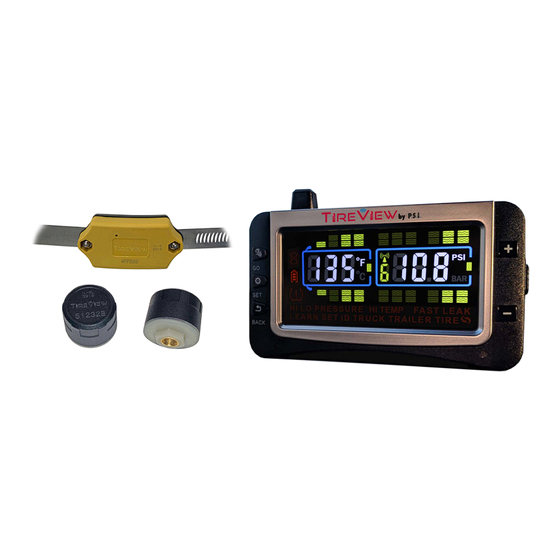
Section 1 - TireView TPMS Instruction Manual ™ The system cannot prevent accidents nor will P.S.I. be responsible for damage or injury due to (a) improper use, ™ (b) failure to follow the product manufacturer’s instructions or to perform preventative maintenance, (c) unauthorized repair or modifications, (d) use of products beyond their useful life, or (e) external causes such as accidents, abuse, or other actions or events outside of P.S.I. - Page 11 Section 1 - TireView TPMS Instruction Manual ™ Rubberized Display Cradle 12 VDC USB Power Cord 12 VDC Power Adapter Repeater Suction Cup Mount T004-01 Rev 06-19 © Pressure Systems International Inc. All rights reserved worldwide.
-
Page 12: Tireview ™ Tpms Display Features
Section 1 - TireView TPMS Instruction Manual ™ Fixed Mount Cap Sensor Internal Sensor Also shown w/ band TireView ™ TPMS Display Features Easy to read display screen Manual On/Off power slide-switch Internal, non-replaceable, lithium-ion battery Includes two mounts; suction cup mount and rubberized display cradle... -
Page 13: Tireview ™ Tpms Display Normal Scrolling
Section 1 - TireView TPMS Instruction Manual ™ TireView ™ TPMS Display Normal Scrolling Automatic scroll/cycle of tire icons every five to six seconds Manual scroll/cycle delay using the + or - buttons 10 second delay after manual scroll/cycle; automatic scroll/cycle resumes after delay TireView ™... -
Page 14: Tireview ™ Tpms Display Icons
Section 1 - TireView TPMS Instruction Manual ™ Figure 3: Display Controls - Back TireView ™ TPMS Display Icons Icon Description Tire Warning °F / °C Temperature unit (Selectable) BAR / PSI Pressure unit (Selectable) Sensor low battery Display battery indicator... -
Page 15: Cap Sensor Features
Section 1 - TireView TPMS Instruction Manual ™ Red light operational indicator; mostly steady with occasional blinking Waterproof Interior or exterior installation There is no set-up needed for the repeater Cap Sensor Features Easy installation on the tire valve stem... -
Page 16: Tireview ™ Tpms Display Specifications
Press the BACK button two times to return to the main screen. Setting ID Trailer Three-Digit Identifier and Trailer Selection Note: Four trailers with sensors can be paired into the TireView TPMS display and each can be selected to be ™... -
Page 17: Programming Sensor Codes Into The Display
Section 1 - TireView TPMS Instruction Manual ™ When selecting a trailer on the TireView TPMS display: ™ Make sure to adjust the high pressure and low pressure alarms for each trailer that has sensors paired to it. On the main screen: Press the GO button to scroll/cycle and view the trailers that have sensors installed on them. -
Page 18: Pressure Code Learning (Option #2)
Section 1 - TireView TPMS Instruction Manual ™ Figure 5: Recommended Sensor Position for Automatic Code Learning The display will capture the sensor code and show it on the screen. Push and release the SET button to save the code to that tire position. When coded correctly, a unique six-digit code will be shown. -
Page 19: Swap Tire Sensor Positions
Press the + button or the - button to select the tire sensor ID code (moved to position). Press the SET button to swap the tire sensor ID code positions. Press the BACK button two times to return to the main screen. Delete Sensor ID Codes from the TireView ™ TPMS Display Delete a Sensor ID Code Press and hold the SET button until it beeps. -
Page 20: Sensor Installation
Section 1 - TireView TPMS Instruction Manual ™ Press and hold the BACK button. Listen for THREE beeps followed by SIX beeps, then release the BACK button. DEL ALL will show on the TPMS display. Press the SET button one time. The TPMS display will beep and all sensor ID codes will be deleted. - Page 21 Section 1 - TireView TPMS Instruction Manual ™ Figure 6: Tire Change Shovel - Correct Position Figure 7: Internal Sensor Rubber Pad T004-01 Rev 06-19 © Pressure Systems International Inc. All rights reserved worldwide.
-
Page 22: Setting The Sensor Alarms
Section 1 - TireView TPMS Instruction Manual ™ Figure 8: Band Clamp Screw Threads Figure 9: Internal Sensor Installation Setting the Sensor Alarms Note: The TPMS display must be powered ON and showing the main screen. Note: Pressure and temperature conversions are provided as a reference only. -
Page 23: Setting The Displayed Pressure Units
Section 1 - TireView TPMS Instruction Manual ™ Low Pressure Alarm 100 PSI (6.9 BAR) Displayed Temperature Units °F High Temperature Alarm 158 °F (70 °C) Setting the Displayed Pressure Units Press and hold the SET button until a beep is heard from the display. -
Page 24: Setting The High Pressure Alarm
Section 1 - TireView TPMS Instruction Manual ™ Figure 12: Low Pressure Set Parameter Screen Press the GO button to scroll/cycle to the next axle. Note: At the trailer section of the display, all the tires will flash. All the trailer axle low pressures can now be set as one group. -
Page 25: Setting The Displayed Temperature Units
Section 1 - TireView TPMS Instruction Manual ™ Figure 14: High Pressure Set Screen Press the GO button to scroll/cycle to the next axle. Note: At the trailer section of the display, all the tires will flash. All the trailer axle high pressures can now be set as one group. -
Page 26: Restore The Tireview ™ Tpms Display To Factory Settings
Section 1 - TireView TPMS Instruction Manual ™ Figure 16: High Temperature Set Screen Press the SET button to enter that mode. Press the + button or the - button to adjust the high temperature alarm. See Figure Figure 17: High Temperature Set Parameter Screen Press the SET button to save the alarm setting. -
Page 27: Fast Leak Alert
Section 1 - TireView TPMS Instruction Manual ™ The audible alarm can be silenced for a short time by pressing any of the buttons on the front of the TPMS display. The red LED warning light will continue to flash until the pressure or temperature issue is resolved and brought back within the preset values. -
Page 28: Tireview ™ Tpms Flow-Thru Bracket Assembly
Section 1 - TireView TPMS Instruction Manual ™ To connect a trailer to the TPMS display: Press the GO button and the - button at the same time. The trailer section on the display will appear and the TPMS display will now read data from the sensors. - Page 29 Section 1 - TireView TPMS Instruction Manual ™ Figure 20: TireView ™ TPMS Flow-thru Bracket - R-spindle Axle Install the two flow-thru bulkhead fittings onto the sides of the flow-thru bracket. Make sure the valve stem threaded end of the flow-thru bulkhead fittings are on the interior of the flow-thru bracket. See Figure ™...
-
Page 30: Tireview ™ Tpms Flow-Thru Bracket Installation
Section 1 - TireView TPMS Instruction Manual ™ Loosely install the inside tire cap sensor and the outside tire cap sensor onto the flow-thru bulkhead fitting valve stems. Make sure the cap sensors are installed in the correct position per the INSIDE and OUTSIDE labels on the flow-thru bracket. - Page 31 Section 1 - TireView TPMS Instruction Manual ™ Figure 23: Tractor Flow-thru Bracket Installed - R-Spindles For N-spindle and P-spindle configurations: Identify and remove hub cap bolts that will be used to attach the flow-thru bracket assembly. Reinstall bolts and washers onto the flow-thru bracket assembly and hub cap. Torque to 12-16 ft- lbs.
-
Page 32: Tireview ™ Tpms System Troubleshooting
Section 1 - TireView TPMS Instruction Manual ™ CAUTION: THE KNURLED ENDS ON THE CP HOSES ARE TO BE HAND-TIGHTENED ONLY. DO NOT USE TOOLS TO TIGHTEN. DAMAGE TO THE KNURLED ENDS CAN OCCUR. Connect and hand tighten the CP short hose (OUTSIDE) knurled end onto the fitting marked OUTSIDE on the flow-thru bracket. - Page 33 If a repeater is installed, check the red LED light on the repeater to make sure that it is operational. An indoor/outdoor thermometer with an external temperature sensor may interfere with the P.S.I. ™ TireView TPMS. Use a thermometer with a higher ™...
- Page 34 Section 1 - TireView TPMS Instruction Manual ™ Issue Solution Visually inspect the tire for damage or defects. Check the tire pressure as this can affect tire temperature. If necessary, have the tire serviced or replaced. There may be a high or low pressure reading from a tire position.
- Page 35 Copyright 2019 Pressure Systems Int'l Inc. All rights reserved worldwide. 4323 Interstate Way, San Antonio, TX 78219 USA Phone: 210.222.1926, Fax: 210.568.4221 www.tireview.com Revision B: June 25, 2019 T004-01 Rev 06-19 T004-01 Rev 06-19 © Pressure Systems International Inc. All rights reserved worldwide.
Need help?
Do you have a question about the TireView and is the answer not in the manual?
Questions and answers