
Summary of Contents for Feig Electronic Sensors VEK CN1-1
- Page 1 Operating Instructions VEK CN1-1 Digital Counter - Stand: 07.12.11 as/ws BES_CN1-1_2011_12_07_GB.doc...
- Page 2 The installation recommendations contained in this guide assume the most favorable circumstances. FEIG ELECTRONIC assumes no liability for perfect function of the traffic detector in a foreign system environment. Photocopying and reproduction of this guide in whole or in part as well as translation into other languages is not permitted without prior written permission from FEIG ELECTRONIC.
-
Page 3: Table Of Contents
Factory Setting _____________________________________________________________________ 12 Installation Instructions ___________________________________________________________ 13 3.1 Input voltage _______________________________________________________________________ 13 3.2 Wiring of Relays Outputs _____________________________________________________________ 14 Technical Data __________________________________________________________________ 14 Safety instructions and Warnings ___________________________________________________ 15 FEIG ELECTRONIC GmbH 12/11... -
Page 4: Functional Description
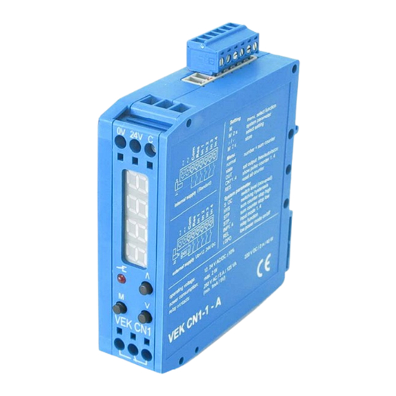
No loss of current data storage in case of power failure • Display of temporary power failure • Compact plastic housing 0.88 ” (22,5 mm) x 3.15 ” (80 mm) x 3.35 ” (85 mm), with DIN-Rail mounting 12/11 FEIG ELECTRONIC GmbH... -
Page 5: Operating Modes
The adjustment parameters and the input pulse counter will not be changed. Is the output state manually set on free or used (see 2.3.3 Set Relay Output manually to “Free” or “Occupied”) so the relay will stay in this state. FEIG ELECTRONIC GmbH 12/11... -
Page 6: Relay Output
During voltage breakdowns the setting values and the counter states remain unchanged. After the voltage returns the counter works on normally. A flashing display shows the counter state must be checked and maybe fixed (see 2.3.1 Power Failure). 12/11 FEIG ELECTRONIC GmbH... -
Page 7: Display And Setup
Cnk4 Input 4 ∧ or ∨ →change Reset all Counter →save M long 2.3.1 Power Failure Display Status Setting ∧ or ∨ → update open space counter 1234 Return after power (flashing) →confirm existing counter failure FEIG ELECTRONIC GmbH 12/11... -
Page 8: Modify/Correct Counter
The open space and passed vehicle counter as well as the four (4) input counter can be reset at ones using the following menu: Display State Setting → 1234 Normal operation M 6 x short = Reset menu → reset all counter Menu item Reset M long → back to normal operation without reset M short 12/11 FEIG ELECTRONIC GmbH... -
Page 9: System Menu - Installation Specific Settings
∧ or ∨ 1 sec. → fast scroll flashes) ∧ or ∨ 3 sec. → 10´s → 100´s → 1000´s → 100´s → 10´s → 1´s → cancel M short → Skor M long = save FEIG ELECTRONIC GmbH 12/11... -
Page 10: Counter Hysteresis
∧ or ∨ 1 sec. → fast scroll digit) ∧ or ∨ 3 sec. → 10´s → 100´s → 1000´s → 100´s → 10´s → 1´s → cancel M short → Stor M long = save 12/11 FEIG ELECTRONIC GmbH... -
Page 11: Display / Input Settings
Change Relay function ∧ → → Fr.on Fr.on oc.on ∨ → → oc.on oc.on Fr.on → cancel (flashing) M short → Skor M long = save Factory default is Normally Open mode for the output relay. FEIG ELECTRONIC GmbH 12/11... -
Page 12: Power Saving Mode
-999 InP1 Function Input 1 incrementing InP2 Function Input 2 decrementing InP3 Function Input 3 incrementing InP4 Function Input 4 decrementing oc.on Output functionality Normaly Open Mode LoPo Power Save Mode off, Display continuously activated 12/11 FEIG ELECTRONIC GmbH... -
Page 13: Installation Instructions
• 12..24V AC Do not connect multiple counter units in parallel! J2 to down and right External 12..24V DC • 12..24V AC/DC Use only one external power supply for all inputs! J2 to up and left FEIG ELECTRONIC GmbH 12/11... -
Page 14: Wiring Of Relays Outputs
Power Supply/Electronics and pins 5.5 mm between pins 3.0 mm between Power Supply/Electronics and pins 0.5 mm Connection Screw Terminal (Power Supply, Relay output) Block Terminals (Input) CE-Standards EN 50082-2, Feb. 1996 EN 50081-1, March 1993 12/11 FEIG ELECTRONIC GmbH... -
Page 15: Safety Instructions And Warnings
• The gold gladded relay contacts will be destroyed for switching currents higher than 100 mA. Relays with such pre-stressed contacts can certainly switch only currents higher than 100 mA. FEIG ELECTRONIC GmbH 12/11... - Page 16 Output Function oc.on normally closed Fr.on normally open LoPo Power Saving Mode off (Display on) on (Display off) FEIG ELECTRONIC GmbH * D-35781 Weilburg * Lange Str. 4 * Tel.: +496471/3109-0 * Fax: +496471/3109-99...
Need help?
Do you have a question about the Sensors VEK CN1-1 and is the answer not in the manual?
Questions and answers