
Summary of Contents for OSTLING PinMark UMC box
- Page 1 Ö S T L I N G Markiersysteme GmbH Broßhauser Str. 27 42697 Solingen - Deutschland Tel.: +49 (0) 212 - 26 96 0 Fax.: +49 (0) 212 - 26 96 199 www.ostling.com Edition: 04/2006...
- Page 2 The document was written in the Technical documentation department of the company ÖSTLING Markiersysteme GmbH. All rights at this documentation, in particular the right of the duplication and spreading as well as the translation are at ÖSTLING Markiersysteme GmbH, also for the case of patent right registrations.
-
Page 3: Table Of Contents
Table of contents Chapter 1 Safety For your safety ..................1-2 Definitions....................1-2 Operational safety ..................1-3 Intended use of the marking system ............1-3 Measures taken by the user/operator ............. 1-4 Consider warning plates and references..........1-4 Personnel instruction................1-4 Duty to care in handling the marking system ........ - Page 4 Description of the components .............. 3-4 Marking unit..................... 3-5 Unit design ................... 3-5 Marking heads..................3-6 Combination unit with marking head ............ 3-7 Marking tools ................... 3-7 Examples for marking tools ..............3-8 Control UMC box................... 3-10 External communication ............... 3-11 Chapter 4 Operation Operating devices and indicators ............
- Page 5 System control ..................4-26 Reading out diagnostic data..............4-26 Operating the marking head in manual operation......... 4-28 Displaying marking head parameters ........... 4-29 Displaying marking head origin ............. 4-30 Selecting the marking tool..............4-31 Setting options..................4-32 Selecting the language............... 4-32 Selecting software adjustments ............
- Page 6 Chapter 7 Index Chapter 8 Drawings, parts lists Chapter 9 EC declaration of conformity Chapter 10 Service request B_PM_UMCbox_en00.doc Table of contents ÖSTLING Markiersysteme GmbH...
-
Page 7: Safety
Chapter 1 Safety For your safety ..................1-2 Definitions....................1-2 Operational safety ..................1-3 Intended use of the marking system ............1-3 Measures taken by the user/operator ............. 1-4 Consider warning plates and references..........1-4 Personnel instruction................1-4 Duty to care in handling the marking system ........1-5 Use of intended spare parts and operational funds ...... -
Page 8: For Your Safety
For your safety The UMC box coining unit has been developed as the newest, state-of-the-art marking system concerning safety and reliability. We confirm that the UMC box marking system meets the fundamental safety and health requirements of the EEC machine guideline 98/37/EG. We provide the "EEC conformity explanation", and the CE-indication on the marking system. -
Page 9: Operational Safety
Operational safety The marking system is built according to the latest state-of-the-art technology, and reliability in service. From this marking system, however, dangers can proceed if it is used by un- trained personnel inappropriately, or to not intended use. This can result in: Dangers for the safety of the operator. -
Page 10: Measures Taken By The User/Operator
3.2 Measures taken by the user/operator Consider warning plates and references Within operation and handling of the marking system, dangers can arise if not handled with proper care. In this manual, operating instructions are given, including appropriate warning references in the front. In addition, warning plates can be found on the marking system. -
Page 11: Duty To Care In Handling The Marking System
Duty to care in handling the marking system Guarantee perfect condition of the installation: The user and/or the circle of acquaintances assigned by him may operate • the marking system exclusively in the perfect condition. The user must ensure cleanliness and clarity of the work place at the mar- •... -
Page 12: Measures Of The Manufacturer
When using the intended operational funds the instructions for use must be kept. As far as a safety data sheet (European guideline 91/155/EWG) of the manufacturer for operational funds is prescribed, the references made there must be considered obligatorily, like e. g.: Chemical characterization. -
Page 13: Danger Overview
Danger overview The following chart outlines potential hazardous risks and endangerment to one's life from the marking system. Through construction and design, as well as implementation of safety devices as defined by the EEC machine guideline 98/37/EG, will prevent dangers and promote safety to personnel. If the user of the marking system can provide additional measures for the prevention of dangers, the user finds these additional measures in the following chart. - Page 14 B_PM_UMCbox_en01.doc Safety ÖSTLING Markiersysteme GmbH...
-
Page 15: Set-Up
Chapter 2 Set-up Installing and setting up the marking system........2-2 Installing the software ................2-3 Built-in units..................... 2-4 Measures to prevent electronic interference ........2-5 Complying with interference suppression as per CE ......2-6 B_PM_UMCbox_en02.doc ÖSTLING Markiersysteme GmbH Set-up... -
Page 16: Installation And Set-Up Of The Marking System
Installation and Set-up of the Marking System 1. Install the marking system in compliance with all safety rules. 2. Supply the marking head with oiled and cleaned compressed air via the designated connection. 26-pin plug of the connection cable 21-pin connection at the marking head 21-pin plug of the connection cable Connection cable for marking head and marking head Fig. -
Page 17: Installing The Software
6. Tuck the 26-pin plug of the connection cable (1) into the 26-pin connection BU1 (10) on the back side of the control UMC box. Ensure the coding pin of the plug is inserted into the flute of the connection. 7. -
Page 18: Built-In Units
1.2 Built-in units Horizontal (on the left) and vertical installation of the marking head Fig. 10262 All marking heads are supplied ready for use. The following points must be con- sidered when installing the marking head into a production line: Built-in units must be installed adjustable to allow subsequent aligning •... -
Page 19: Measures To Prevent Electronic Interference
With vertical/lateral installation of the marking head (front of the marking head shows upward), the following points must be additionally considered: Marking tool can move down by itself, since the driving motors are dead • after switching off the marking equipment and possess no automatic locking. -
Page 20: Complying With Interference Suppression As Per Ce
2.1 Complying with interference suppression as per CE The marking system UMC box, coining unit, is designed and build according to the regulations of the electromagnetic compatibility guideline. To ensure interference suppression the following points must be considered: Use shielded control cables to connect all external components (e. g. •... -
Page 21: Description
Chapter 3 Description Short description..................3-2 Technical data ..................3-2 Marking units ................... 3-2 Control UMC box..................3-3 Software ....................3-3 Description of the components .............. 3-4 Marking unit..................... 3-5 Unit design ................... 3-5 Marking heads..................3-6 Combination unit with marking head ............ 3-7 Marking tools ................... -
Page 22: Short Description
Short description The UMC box, coining unit, is a marking system for marking products through coining. Coining When coining, the marking takes place via a carbide point, which is brought to oscillating by compressed air. The carbide point is moved in X- and Y-direction by a coordinate unit with two stepping motors. -
Page 23: Control Umc Box
2.2 Control UMC box Computer external PC System requirements Intel Pentium or equivalent computer with Microsoft Windows 2000 or XP clock frequency [GHz] RAM [MB] hard disc space [MB] colour monitor [Pixel] min. 1024 x 768, 65K colours CD drive Ports COM (RS232, RS485) Memory... -
Page 24: Description Of The Components
Description of the components Connection cable control - Control UMC box External PC for Software marking head PinWare (not included in Foot switch delivery) Marking head (here: MagicPin) PC connecting cable 24 V power supply with line cord Components of the marking system Fig. -
Page 25: Marking Unit
3.1 Marking unit Unit design 4 different unit designs are available: Table unit. • Hand-held unit. • Built-in unit. • Combination unit (combination of table unit and hand-held unit). • Customized special designs are also possible. Table unit With the table unit, the marking head is attached to a stand. The marking head can be manually moved up and down (Z-axis). -
Page 26: Marking Heads
Hand-held unit With the hand-held unit, the marking head is put on the workpiece manually with a handle or a double handle. At the handle there is a releasing pushbutton for the start of the marking. Built-in unit The built-in unit corresponds to the table device without stand. It is intended for the installation into production and assembly lines. -
Page 27: Combination Unit With Marking Head
Combination unit with marking head Not every marking head is available in every unit design: Designation Size of the Table unit Hand-held Built-in unit Combination marking marking field unit unit head [mm] MagicPin 30 x 50 3 / 5 30 x 50 4 / 6 40 x 60 5 / 9... -
Page 28: Examples For Marking Tools
Examples for marking tools Note Not all marking tools can be used in each marking head. There are different sizes of tool fittings. Coining tool WE 2 Coining tool WE 3 Art.-Nr. 45.22.0000 Art.-Nr. 45.30.0000 blue housing red housing • •... - Page 29 Coining tool WP 3 Deep coining tool WE 1 Art.-Nr. 45.70.0000 Art.-Nr. 45.10.0000 black housing • This needle does not begin The needle tip is brought to swing independently independent swinging when it is subjected with compressed air. The fre- compressed air.
-
Page 30: Control Umc Box
3.3 Control UMC box All coining heads of the PinMark family can be controlled by the control UMC box. The external PC (not included in delivery) communicates with the control over the RS232 interface. In addition the control and thus the entire marking system can be controlled from external. -
Page 31: External Communication
External communication The marking system can communicate with external controls via the connection BU2. Digital I/O signals are sent via this connection, e. g. start with foot switch, ready for operation, ready to mark, marking and E-STOP. The high level of the input signals is defined between 17 -30 V DC, the high level for output signals will be 24 V DC. - Page 32 B_PM_UMCbox_en03.doc 3-12 Description ÖSTLING Markiersysteme GmbH...
- Page 33 Chapter 4 Operation Operating devices and indicators ............4-3 Pushbuttons .................... 4-3 Status-LEDs .................... 4-4 Basics of operation .................. 4-5 Text fields, Masks and Projects .............. 4-5 Switching on and off the control .............. 4-6 Switching on the control ............... 4-6 Switching off the control ...............
- Page 34 System control ..................4-26 Reading out diagnostic data..............4-26 Operating the marking head in manual operation......... 4-28 Displaying marking head parameters ........... 4-29 Displaying marking head origin ............. 4-30 Selecting the marking tool..............4-31 Setting options..................4-32 Selecting the language............... 4-32 Selecting software adjustments ............
-
Page 35: Operating Devices And Indicators
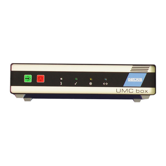
Operating devices and indicators The following operating devices are available at the UMC box: Pushbutton ENTER for acknowledgment and start of the marking. • Pushbutton ESC for program abort. • The following indicators are available at the UMC box: 4 status LEDs. •... -
Page 36: Status-Leds
1.2 Status-LEDs 4 coloured LEDs are situated at the front of the UMC box. They indicate the current status of the marking system. After switching on the UMC box the LEDs are tested: all 4 LEDs are switched on and off again for 3 s one after the other. The white LED "Power on" remains switched on. -
Page 37: Basics Of Operation
Basics of operation 2.1 Text fields, Masks and Projects The software is based on the use of text fields and masks. Several text fields which belong to one workpiece are combined in a mask. A mask can contain max. 31 text fields. A text field can contain max. 50 characters or one graphic. If more than 31 text fields are needed for the marking of a workpiece, several masks must be created. -
Page 38: Switching On And Off The Control
2.2 Switching on and off the control Switching on the control Electronics damage to control possible! Control must be switched off for at least 20 s before switching on. Switch on MAIN SWITCH. Control boots, axes of the marking head reference: the slide of the marking head moves in X-direction until the X-initiator actuates. -
Page 39: Switching Off The Control
Switching off the control 1. Save all changes of the current mask or project (see pages 4-19 and 4-20). 2. After no keys is pressed for a short time: switch off MAIN SWITCH. 2.3 Brief instruction: marking a workpiece 1. Switch on control via MAIN SWITCH. 2. -
Page 40: Working With Masks
Working with masks 3.1 Creating a text field Several text fields which belong to one workpiece are combined in a mask. A mask can contain max. 31 text fields. If more than 31 text fields are needed for the marking of a workpiece, several masks must be created. Type text field 5 different types of text field are available: Text: text is aligned on a straight line. -
Page 41: Creating A New Text Field
Creating a new text field 1. Select File > New mask. "Mask Data" appears. Mask "Mask Data" Fig. 10221en 2. Enter the number of the text field behind "Textfield". 3. Select the desired type of text field (see page 4-8) behind "Type". Depending on the selected "Type"... - Page 42 10. If the text shall not be marked on a horizontal line: enter the desired angle of rotation of the text in [° ] under "Angle". A vertical text corresponds to an angle of 90° . 11. Enter the diameter of the circular arc in [mm] under "Diameter", if circular text is marked.
-
Page 43: Editing A Text Field
Editing a text field A text field that is already created can be edited in the edit or service mode at any time. 1. If the mask in which the text field shall be edited is not the current mask: select File >... -
Page 44: Working With Wildcards
3.2 Working with wildcards Instead of text also a wildcard can be entered in a text field. With wildcards variable information (e. g. current date or time) can be marked. The information isn't queried by the system until the marking takes place. Wildcards are included by 2 "@"... -
Page 45: Creating A Counter
Objects are saved in an object list and can be inserted in as many masks as de- sired. E. g. if a four-digit counter is needed on several different workpieces, which begins with 0 and ends with 250, this counter must be created only once. Note If "Autosave"... - Page 46 3. Enter the following values: "Value": current value of the counter. Select "User" if the current value of the counter shall be queried from the user by a message (see also Fig. 10235, page 4-16). "Begin": minimal value of the counter. "End": maximal value of the counter.
-
Page 47: Creating The Object "Date And Time
Creating the object "Date and Time" 1. Select Edit > Object List. Select OL in "Mask Data". "Object List" appears. 2. Select unimplemented object or object "Counter" to be changed and select ENTER. 3. Select "Date and Time" in the field on the right. Mask "Date and Time Object"... -
Page 48: Creating The Object "User Input
Creating the object "User Input" 1. Select Edit > Object List. Select OL in "Mask Data". "Object List" appears. 2. Select unimplemented object or object "Counter" to be changed and select ENTER. 3. Select "User Input" in the field on the right. Mask "User Input"... -
Page 49: Creating A Shift Index
"Default Data": data that is displayed in the message behind "Please enter data" (see Fig. 10235). "Current Data": enter nothing. These are the data that are entered by the user just before the marking. "Length": max. number of digits of the text to be marked. 5. - Page 50 4. Enter the following values: "Shift start": enter the hour of the shift start in the first column. Enter the minute of the shift start in the second column. "Text": displayed text, when the current time corresponds to the rela- tive shift.
-
Page 51: Saving Masks
3.4 Saving masks 1. Create the mask with all desired text fields (see paragraph 3.1, page 4-8). 2. Select File > Save Mask. If a new mask is saved (mask doesn't have a file name yet) "Save File" appears. If the mask has been saved once and therefore has a file name, the mask will be saved. -
Page 52: Working With Projects
Working with projects If the same masks are used on different marking units with different marking heads, the masks can be stored as projects. Beside the mask with all text fields a project contains also all current adjustments e. g. used marking head. If the mask is stored as project, these adjustments must be entered only once for each marking head. -
Page 53: Opening A Project
4.2 Opening a project 1. Select File > Open Project. "Load File" appears. Mask "Load File" Fig. 10268en 2. Select the desired file (project). 3. Select Project is opened: mask which is stored in this project is opened, all stored adjustments are assumed by the control. -
Page 54: Marking A Workpiece
Marking a workpiece 5.1 Preview on marking 1. To see a preview of the mask to be marked: select Marking > Preview. Select in "Mask Data". "Preview" appears. Mask "Preview" Fig. 10269en 2. To scale up the view: select 3. To reset the view to normal view: select 4. -
Page 55: Starting The Marking
5.2 Starting the marking 1. Select Marking > Start. Select Start in "Preview". "Print" appears. Mask "Print" Fig. 10270en 2. Enter the number of workpieces to be marked behind "Number". 3. Select , to start the marking. After the marking, the system indicates behind "Time" how long the marking has lasted in [s]. -
Page 56: Further Functions
Further functions 6.1 Importing data Texts from files which are on an external storage medium (disk, net drive assembly) can be imported. The software assumes all characters from the file. These characters are inserted in one or more text fields of one or several masks. -
Page 57: Changing The Mode
6. Enter the import options (see also Fig. 10272): "Active line number": enter the line number of the file with the data to be imported, from which the import is started. Each line of the file is used as a mask. "Separator": enter the character that separates the individual texts in one line, e. -
Page 58: System Control
System control 7.1 Reading out diagnostic data Select System > Diagnostic. "Diagnostic" appears. Mask "Diagnostic" Fig. 10247en Pinware Version: software version that is installed on the control. • Install Version: version of the compact flash card. • Firmware Version: software version of the motor card. •... - Page 59 middle Motor voltage: voltage in No voltage. [V] that is impressed to the Voltage OK. motor. High voltage. To high voltage, error. Low voltage. Too low voltage, error. 2. from Heat sink temperature Sensor not attached. right Temperature OK. High temperature. Too high temperature, error.
-
Page 60: Operating The Marking Head In Manual Operation
7.2 Operating the marking head in manual operation 1. Select System > Manual Control. "Manual Operation" appears. Mask "Manual Operation" Fig. 10240en 2. To move the marking tool manually: enter step width in [mm]. 3. Select F6 to F9 to move the marking tool in the desired direction. 4. -
Page 61: Displaying Marking Head Parameters
7.3 Displaying marking head parameters 1. Select System > Marking Head Parameters. "Markinghead Parameters" appears. 2. Select "MotorCard". Mask "Markinghead Parameter", tab "MotorCard" Fig. 10248en Current: motor current in [mA]. • Boost: increase of the motor current in [mA] during ramping. •... -
Page 62: Displaying Marking Head Origin
7.4 Displaying marking head origin Select System > Marking Head Origin. "Markinghead Origin" appears. Mask "Markinghead Origin" Fig. 10249en Origin: origin of the X- and Y-axis in [mm]. For hand-held units it is useful to • displace the origin in order that the marking isn't "turned upside down". Scale: the value "-1"... -
Page 63: Selecting The Marking Tool
7.5 Selecting the marking tool 1. Select System > Needle Parameters. "Needle Parameters" appears. Mask "Needle Parameters" Fig. 10250en 2. Select the desired marking tool behind "Needle Type". Image of the selected marking tool is displayed. 3. If desired, change the parameters of the marking tool: Turn-on delay: The needle of the marking tool is brought to oscillating by compressed air. -
Page 64: Setting Options
7.6 Setting options Selecting the language 1. Select System > Options. "Options" appears. Mask "Options", Tab "Language" Fig. 10394en 2. Select the desired language. 3. To convert the software into the selected language: select B_PM_UMCbox_en04.doc 4-32 Operation ÖSTLING Markiersysteme GmbH... -
Page 65: Selecting Software Adjustments
Selecting software adjustments 1. Select System > Options. "Options" appears. 2. Select "Pinware". Mask "Options", Tab "Pinware" Fig. 10395en Autostart: If selected the page "Print" appears directly when booting the • control. Autosave: If selected the current mask is saved after each marking. Use •... -
Page 66: Changing The Start Mode Of The Control
Changing the start mode of the control 1. Select System > Options. "Options" appears. 2. Select "Mode". Mask "Options", Tab "Mode" Fig. 10396en 3. Select the desired start mode: Work mode: files (projects and masks) can be loaded and marked. Edit mode: files (projects and masks) can be loaded, changed and marked. -
Page 67: Fonts
Fonts 15 different fonts are available in the software. By default the software uses the font 'litt.chr'. To select another font: select CHR in "Mask Data" and select the desired font from the list (see page 4-10). For every individual of the 31 text fields of a mask you can select another font. As a result of the different layouts of the individual fonts however differences can arise in the character width, height and size. -
Page 68: Further Fonts
This font is a proportionally font, i. e. the individual letters possess different character widths (e. g. a W is wider than an i). The following illustration clarifies the structure of the characters by the example of the Ö and y: Structure of font 'litt.chr' Fig. - Page 69 Font 'bold.chr' Fig. 10277 Font 'd5x7.chr' Fig. 10278 Font 'euro.chr' Fig. 10280 Font 'goth.chr' Fig. 10281 B_PM_UMCbox_en04.doc 4-37 ÖSTLING Markiersysteme GmbH Operation...
- Page 70 Font 'lcom.chr' Fig. 10282 Font 'ocra.chr' Fig. 10284 Font 'rlit.chr' Fig. 10285 Font 'rtri.chr' Fig. 10286 B_PM_UMCbox_en04.doc 4-38 Operation ÖSTLING Markiersysteme GmbH...
- Page 71 Font 'sans.chr' Fig. 10287 Font 'scri.chr' Fig. 10288 Font 'sima.chr' Fig. 10289 Font 'simp.chr' Fig. 10290 B_PM_UMCbox_en04.doc 4-39 ÖSTLING Markiersysteme GmbH Operation...
- Page 72 Font 'trip.chr' Fig. 10291 Font 'tscr.chr' Fig. 10292 B_PM_UMCbox_en04.doc 4-40 Operation ÖSTLING Markiersysteme GmbH...
- Page 73 Chapter 5 Maintenance General Guidelines for maintenance............5-2 Maintenance overview ................5-3 Lubricants....................5-3 Mechanical parts ..................5-4 Maintenance overview ................5-4 Maintenance instructions ................ 5-5 Exhaust air silencer ................5-5 Toothed belts of the axes ..............5-6 Slides of the axes ................. 5-8 Pneumatic parts ..................
-
Page 74: General Guidelines For Maintenance
General Guidelines for maintenance Note Unprofessional usage of controls or marking head voids the warranty. General guidelines for maintenance: With all adjustments, maintenance and repair works, the control must • always be switched off and the marking unit must be separated from the power supply. -
Page 75: Maintenance Overview
1.1 Maintenance overview Operating hours Maintenance place Maintenance work Page Slides of the axes Check the slides on smooth running 2000 Exhaust air silencer Clean the silencer, change it if necessary If necessary Toothed belts of the Check the toothed belts on wear axes Check the tension of the toothed belts If necessary... -
Page 76: Mechanical Parts
Mechanical parts 2.1 Maintenance overview Toothed belts of the axes Slides of the axes Exhaust air silencer Fig. 10641 B_PM_UMCbox_en05.doc Maintenance ÖSTLING Markiersysteme GmbH... -
Page 77: Maintenance Instructions
2.2 Maintenance instructions Exhaust air silencer (see page 5-4) Clean the Every 2000 operating hours. silencer 1. With table or built-in unit: move the marking head completely upward. With hand-held units: turn the marking head upside down. 2. Switch off the control and pull the power supply plug. Silencer Marking head from the bottom Fig. -
Page 78: Toothed Belts Of The Axes
Toothed belts of the axes (see page 5-4) Check the If necessary, i. e. if the slides (see page 5-8) are tight or with loss of quality of toothed belts the marking. 1. Switch off the control and pull the power supply plug. 2. - Page 79 Change a If necessary, i. e. if the tension of the toothed belt is too low or a toothed belt is toothed belt worn out. 1. Switch off the control and pull the power supply plug. 2. Unscrew the covering cap of the marking head. 3.
-
Page 80: Slides Of The Axes
Slides of the axes (see page 5-4) Check on Every 40 operating hours. smooth running 1. Switch off the control. 2. Move the slides manually in X- and Y-direction. Slides must be movable easily by hand. 3. If the slides can be moved only with difficulty: lubricate the guiding rods of the axes: Rear guiding rod of the X-axis Left guiding rod of the Y-axis... -
Page 81: Pneumatic Parts
Pneumatic parts 3.1 Maintenance overview Pneumatic maintenance unit Fig. 10640 B_PM_UMCbox_en05.doc ÖSTLING Markiersysteme GmbH Maintenance... -
Page 82: Maintenance Instruction
3.2 Maintenance instruction Pneumatic maintenance unit Note 2 different maintenance units are used at the PinMark marking units. Type of maintenance unit FESTO type All marking tools Filter control valve with Festo LFR 1/8 D-Mini pressure reducer Marking tools WE 1 and/or Filter control valve with Festo FRC 1/8 D-Mini, WE 4 with hardened steel... -
Page 83: Connector Pin Lists
Chapter 6 Connector pin lists Marking head .................... 6-2 Plug to UMC box ..................6-2 Stepping motors ..................6-3 Colour coding ..................6-3 Circuit ....................6-3 Control UMC box ..................6-4 Socket BU1 to marking head ..............6-5 Socket BU2 ..................... 6-6 Serial port START ................... -
Page 84: Marking Head
Marking head 1.1 Plug to UMC box The plug for the connection of the marking head to the control UMC 112 has 21 pins. Axis Colour of Name Remark the cable pink motor X-axis: phase 2A black motor X-axis: phase 1A blue motor X-axis: phase 2B green... -
Page 85: Stepping Motors
1.2 Stepping motors Colour coding Phase Colour of the cable Phase Colour of the cable Phase 1A black Phase 2A Phase 1B orange Phase 2B yellow Jumper 1 black - white/ Jumper 2 red - white/ orange -white yellow - white Tab. -
Page 86: Control Umc Box
Control UMC box Back side of the control UMC box Fig. 10388 B_PM_UMCbox_en06.doc Connector pin lists ÖSTLING Markiersysteme GmbH... -
Page 87: Socket Bu1 To Marking Head
2.1 Socket BU1 to marking head The plug BU1 for the connection of the marking head to the control has 26 pins. Name Remark motor X-axis: phase 2A motor X-axis: phase 1A motor X-axis: phase 2B motor X-axis: phase 1B motor Y-axis: phase 2A motor Y-axis: phase 1A motor Y-axis: phase 2B... -
Page 88: Socket Bu2
2.2 Socket BU2 The socket BU2 for standard digital I/O communication has 37 pins. With this connection the current status of the marking head can be queried or releases can be sent. The high level of the input signals is defined between 17 -30 V DC, the high level for output signals will be 24 V DC. -
Page 89: Serial Port Start
GND 24 V DC GND 24 V DC GND 24 V DC +24 V DC +24 V DC internal voltage +24 V DC +24 V DC internal voltage not used E1.0 foot switch start max. +25 V DC not used E1.4 reserved E1.6... -
Page 90: Connection Cable For Marking Head
Connection cable for marking head Colour of the cable Name Remark white motor X-axis: phase 2A brown motor X-axis: phase 1A green motor X-axis: phase 2B yellow motor X-axis: phase 1B pink motor Y-axis: phase 2A grey motor Y-axis: phase 1A blue motor Y-axis: phase 2B motor Y-axis: phase 1B... - Page 91 Chapter 7 Index B_PM_UMCbox_en07.doc ÖSTLING Markiersysteme GmbH Index...
- Page 92 Axes............. 3-6 Hand-held unit..........3-6 Homing............4-6 HPGL ............4-8 Basing point ..........4-6 Bellows ............2-4 Built-in unit ..........2-4, 3-6 Import............4-24 vertical, lateral installation......2-5 Initiator ............4-29 Installation ............ 2-2 Software ........... 2-3 Interference suppression ......2-6 Circular text ..........
- Page 93 Needle parameters ........4-31 Set-up ............2-2 Shift index ..........4-17 Software ............. 3-10 install ............2-3 Object ............4-12 Spare parts ..........1-5 Counter ..........4-13 Stepping motor Date and time......... 4-15 Circuit ............6-3 Shift index ..........4-17 Switch off .............
-
Page 94: B_Pm_Umcbox_En00.Doc
B_PM_UMCbox_en07.doc Index ÖSTLING Markiersysteme GmbH... - Page 95 Chapter 8 Drawings, parts lists B_PM_UMCbox_en08.doc ÖSTLING Markiersysteme GmbH Drawings, parts lists...
- Page 96 B_PM_UMCbox_en08.doc Drawings, parts lists ÖSTLING Markiersysteme GmbH...
- Page 97 Chapter 9 EC declaration of conformity B_PM_UMCbox_en09.doc ÖSTLING Markiersysteme GmbH EC declaration of conformity...
- Page 98 B_PM_UMCbox_en09.doc EC declaration of conformity ÖSTLING Markiersysteme GmbH...
- Page 99 EC conformity declaration in terms of EC directives - Machines 98/37/EG - Electromagnetic compatibility 89/336/EWG - Low voltage 73/23/EWG Hereby we declare that the below designated machine corresponds to the fundamental safety and health requirements of the mentioned EC directives machines in its conceiving and design as well as in the execution brought in circulation by us.
- Page 101 Chapter 10 Service request B_PM_UMCbox_en10.doc 10-1 ÖSTLING Markiersysteme GmbH Service request...
- Page 102 B_PM_UMCbox_en10.doc 10-2 Service request ÖSTLING Markiersysteme GmbH...
- Page 103 Request for service of company Markiersysteme für Billing address: Produkt und Verpackung Östling Markiersysteme GmbH Broßhauser Straße 27 42697 Solingen Tel: 0212 / 2696 - 0 Fax: 0212 / 2696 - 199 Gewährleistung Location of machine (if different to above): Kulanz Rechnung Termin:...
- Page 105 ÖSTLING - worldwide ÖSTLING Markiersysteme GmbH Broßhauser Str. 27 D-42697 Solingen Tel.: +49 - 212 - 26 96 0 Fax.: +49 - 212 - 26 96 199 Internet: http://www.ostling.com E-mail: info@ostling.com Switzerland France ÖSTLING ÖSTLING Markiersysteme AG Système de Marquage Eichenweg 16 Technopôle Metz 2000...
Need help?
Do you have a question about the PinMark UMC box and is the answer not in the manual?
Questions and answers