Table of Contents
Advertisement
Advertisement
Table of Contents

Summary of Contents for UYAR VisionLine RWC
- Page 1 Operating instructions VisionLine RWC VisionLine EAC VisionLine EC...
-
Page 2: Table Of Contents
Operating instructions VisionLine Inhaltsverzeichnis Notes on symbols and markings �������������������������������������������������������������������� 3 Preface ���������������������������������������������������������������������������������������������������������� 4 Illustration of the EC declaration of conformity VisionLine RWC ���������������������� 5 1 Introduction ���������������������������������������������������������������������������������������������� 7 1.1 Liability ....................7 1.2 Warranty ....................7 1.3 Return andhandling ................. 8 2 Description of the camera system ��������������������������������������������������������������... -
Page 3: Notes On Symbols And Markings
Operating instructions VisionLine Notes on symbols and markings This operating manual uses symbols and images to help you understand how to use the product safely and to warn you of potential hazards due to incorrect connection, mounting, selection and operation. It is important that you know the meaning of the notes to this manual exactly in order to use this camera system correctly. -
Page 4: Preface
©2018 by A.U. Uyar Technology Center e.K. Copyright of the operating instructions The copyright to this manual remains with the A.U. Uyar Technology Center e.K.. These operating instructions are intended for the operating personnel. It contains rules and drawings of a technical nature which are not allowed, neither as a whole nor in part, to be reproduced, distributed or exploited for the purposes of competition without authorization or communicated to others. -
Page 5: Illustration Of The Ec Declaration Of Conformity Visionline Rwc
Operating instructions VisionLine Illustration of the EC declaration of conformity VisionLine RWC Werkzeugmaschinen Kamera Typ: RWC 88 HDMI 2.6.2 EU-Konformitätserklärung Technology Center e.K. Carl-Bosch-Straße 6 D-33790 Halle (Westfalen) EU-Konformitätserklärung im Sinne der EU-Richtlinie Elektrische Betriebsmittel 2014/35/EU (ab 20.04.2016) EU-Richtlinie EMV 2014/30/EU (ab 20.04.2016) - Page 6 Operating instructions VisionLine...
-
Page 7: Introduction
In these cases the liability is transferred to the operator. A.U. UYAR Technology Center e.K. will charge the operator for any resulting repairs. The manufacturer is not liable for any accidental loss resulting through thedue to use or non-use of this product, such as loss of business incomesprofits. -
Page 8: Return Andhandling
The UYAR camera systems of the RWC and EAC series are mounted inside the working area of a machine tool. The rotating special pane of glass in the VisionLine RWC throws both the impinging coolant and the chips away to the outside and thus out of sight. - Page 9 Operating instructions VisionLine VisionLine EC Thanks to the well-sealed housing with IP67 standard, the VisionLine EC models can be used wherever conventional cameras fail after a short time. The housing of the VisionLine EC is not only dust- and waterproof: All seals are also resistant to oils and cooling lubricants. NOTICE The coolant jet must not be directed at the camera system.
-
Page 10: Structure Of The Camera Systems
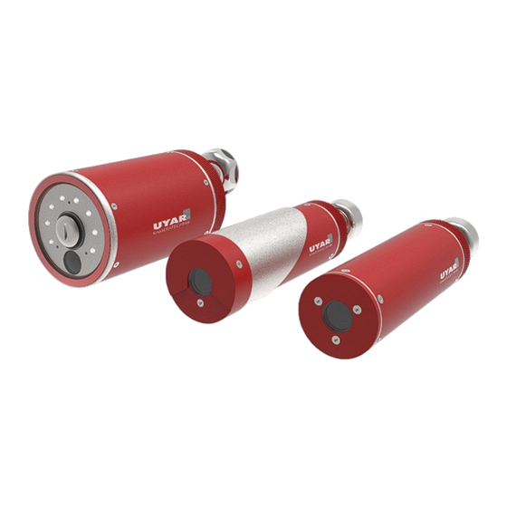
Operating instructions VisionLine 2�2 Structure of the camera systems 2�2�1 VisionLine RWC 2�2�2 VisionLine EAC... - Page 11 Operating instructions VisionLine 2�2�3 VisionLine EC 2�2�4 Hinge options Hinge option 1 Hinge option 2 with external ball joint with integrated ball joint and cable bushing...
-
Page 12: Installation
These installation instructions include the standard installation for industrial processing machines. Ho- wever, depending on the type of construction or the type of system another mounting style can be more appropriate. If you have any questions, please contact us directly: A.U. Uyar Technology Center e.K. Carl-Bosch-Straße 6 33790 Halle (Westf.) -
Page 13: Mechanical Installation
Operating instructions VisionLine 3�2 Mechanical installation The following installation instructions are valid for the VisionLine RWC, EAC and EC models. A differentiation is made in the mechanical installation between the various hinge and installation options. Please refer to one of the following chapters for the respective installation instructions for your camera: 3.2.1 Mounting the camera with external ball joint... - Page 14 Operating instructions VisionLine Mounting the camera 1. counter-sunk screw 2. washer 3. machine wall 4. o-ring 5. external ball joint If you have not purchased a magnetic holder for your camera system, a Ø8.2mm hole is required at the position specified in Chapter 3.1. Here the camera is attached to the external ball joint (incl. O-ring) with washer and countersunk screw (included in delivery) according to the above exploded view.
- Page 15 Operating instructions VisionLine Mounting of the control box via the cable-hose-package: At the chosen position a Ø30mm hole is needed in the machine wall. This should preferably be done with a step drill or a sheet metal punch. Carry the wall mount (no. 1) with the attached flat seal (no. 4) from the interior of the machine through the hole.
- Page 16 Operating instructions VisionLine 3�2�2 Direct wall mounting with integrated ball joint without hose assembly Preparations on the machine tool: At the chosen position a Ø30mm hole is needed in the machine wall. This should preferably be done with a step drill or a sheet metal punch. Installation of the control box: Carry the wall mount (no.
- Page 17 Operating instructions VisionLine 3�2�3 Wall mounting with integrated ball joint and cable-hose-package Preparations on the machine tool: At the chosen position a Ø30mm hole is needed in the machine wall. This should preferably be done with a step drill or a sheet metal punch. Installation of wall mount, wall connection and camera: Guide the wall mount (no.
- Page 18 Operating instructions VisionLine 3�2�4 Installation of the optional wall bushing „double socket“ 1. hose connector 2. double socket 3. machine wall 4.hose connector Once the camera is positioned, a suitable position must be found for the wall bushing of the cab- le-hose -package.
- Page 19 Operating instructions VisionLine 3�2�5 Hose mounting If you are using an optional wall bushing „double socket“ ,you must cut the hose at the suitable positi- on. For this purpose, temporarily lay the hose between the camera and the wall bushing and mark the separation point.
-
Page 20: Electrical Installation
During the mechanical installation the cables of the camera were already inserted into the control box. These must now be connected to the (control) electronics of the control box. Please note the different power connection instructions for the models VisionLine RWC and VisionLine EAC/EC! - Page 21 Operating instructions VisionLine 3�3�1 Connect the power connector of VisionLine RWC to the control box board 1. Mounting PE- cable 2. HDMI socket 3. Connector X2 (4-pole) 4. Connector X4 (2-pole) 5. Potentiometer for the engine Motor speed First loosen the marked fixing screw (pos. 1) of the upper board and thread the hook eye of the PE cable under the washer.
- Page 22 Operating instructions VisionLine 3�3�2 Connect the power connector of VisionLine EAC/EC to the control box board 1. Connector X2 (2-pole) 2. HDM socket 3. Mounting PE cable First loosen the marked fixing screw (pos. 3) of the upper board and thread the hook eye of the PE cable under the washer.
-
Page 23: Pneumatic Installation
Operating instructions VisionLine 3�4 Pneumatic installation CAUTION Make sure that the system is not under pressure before starting to work! Risk of injury! Notice for the Model VisionLine EC: Since the VisionLine EC model does not need to be supplied with compressed air, a blanking plug is located in the compressed air inlet of the control box when delivered. -
Page 24: Operation
To do this, press the „Lighting on / off“ push-button on the operating unit. After turning on the switch, the power LEDs in the camera body light up and the switch is highlighted with a green light. The optional control unit is only available for the VisionLine RWC camera system. -
Page 25: Control
In addition, the LED lamps can be switched on and off separately with the operating unit. The VisionLine RWC model can be temporarily taken out of service and still remain in the running ma- chine tool. First switch off the camera system as described above. -
Page 26: Maintenance / Servicing
With our special glass panes, which are installed in all models of the VisionLine RWC, you have acqui- red a low-maintenance and robust product that makes it easy to clean or even change the special glass pane. - Page 27 The glas pane of all models can be changed in a few easy steps. Pane change VisionLine RWC 1. Clamping Screw 2. Special glass pane 3.
- Page 28 Operating instructions VisionLine Pane change VisionLine EAC 1. Countersunk screw M3x8 2. Air attachment 3. Countersunk screw M3x5 4. Special glass pane 5. O-ring 6. Camera housing EAC First loosen the three countersunk screws (pos. 1) from the air attachment (pos. 2). Then remove it from the camera housing (pos.
-
Page 29: Error Diagnostics
Monitor is not switched on / Switch on the monitor connected VisionLine RWC Frequency of the machine LED and Slightly increase the speed of the motor. On the displayed picture a „swimming“ rotation of the special glass pane See chap. -
Page 30: Decomissioning / Disposal
(to reduce the speed) with a screwdriver. Finally close the control box properly! If the disturbances cannot be remedied by the listed steps or repeat frequently, please contact directly: A.U. Uyar Technology Center e.K. Carl-Bosch-Straße 6 33790 Halle (Westf.)
Need help?
Do you have a question about the VisionLine RWC and is the answer not in the manual?
Questions and answers