Advertisement
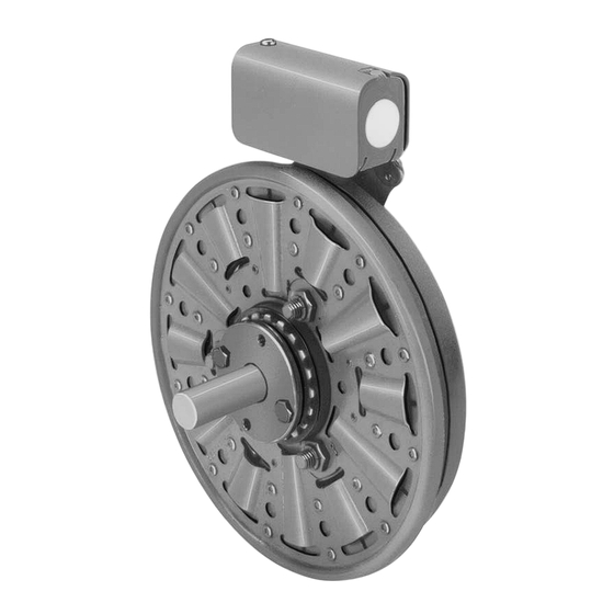
Primary Brake Spline Drive Armature
Pb-825, PB-1000, PB-1225, PB-1525
Installation Instructions
P-209-WE
819-0517
Advertisement

Related Manuals for Warner Electric PB-825

Summary of Contents for Warner Electric PB-825
- Page 1 Primary Brake Spline Drive Armature PB-825, PB-1000, PB-1225, PB-1525 Installation Instructions P-209-WE 819-0517...
-
Page 2: Table Of Contents
PB-825 . . . . . . . . . . . . . . . . . . . . - Page 3 Spline Drive Armature capscrews and lockwashers . (See Figure 2 .) PB-825 PB-1000 PB-1225 PB-1525 The illustration drawings, parts lists, and exploded views for these units can be found beginning on page 8 .
- Page 4 . (See Figure 7 .) Step 3 Turn the armature-adapter assembly over, and insert the retainer ring in the groove . (See Figure 5 .) Figure 7 Figure 5 4 Warner Electric • 800-825-9050 P-209-WE • 819-0517...
- Page 5 258 .4 Current — Amperes 4 .74 1 .18 4 .87 1 .22 .36 4 .5 1 .08 .34 4 .13 1 .21 .35 Watts Coil Build-up — Milliseconds Coil Decay — Milliseconds Warner Electric • 800-825-9050 P-209-WE • 819-0517 5...
-
Page 6: Burnishing And Maintenance
Intimate metal to metal contact is essential between below the metal poles . the armature and the metal rings (poles) of the magnet or rotor . Warner Electric clutches and brakes Heat: Excessive heat and high operating leave the factory with the friction material slightly temperatures are causes of rapid wear . -
Page 7: Pb-825
If the above checks indicate that the proper voltage and current is being supplied to the magnet, mechanical parts should be checked to assure that they are in good operating condition and properly installed . Warner Electric • 800-825-9050 P-209-WE • 819-0517 7... - Page 8 1 . Squareness of magnet mounting face with armature shaft within .006 T .I .R . 2 . Concentricity of magnet mounting pilot diame ter with armature shaft within .010 T .I .R . 8 Warner Electric • 800-825-9050 P-209-WE • 819-0517...
- Page 9 Mounting Accessory - O .M . 5321-101-002 Magnet - Inside Mounted Example: 6 Volt 5311-631-002 24 Volt 5311-631-003 PB-825 Brake per I-25567 - 90 Volt, 1” Bore, Inside 90 Volt 5311-631-004 Mounted †90 Volt LK Facing 5311-631-011 6A-1 Terminal Accessory...
-
Page 10: Pb-1000
1 . Squareness of magnet mounting face with armature shaft within .006 T .I .R . 2 . Concentricity of magnet mounting pilot diame ter with armature shaft within .010 T .I .R . 10 Warner Electric • 800-825-9050 P-209-WE • 819-0517... - Page 11 Terminal Accessory 5311-101-001 These units, when used in conjunction with the Magnet - Outside Mounted 6 Volt 5312-631-011 correct Warner Electric conduit box, meet the 24 Volt 5312-631-013 standards of UL508 and are listed under guide card 90 Volt 5312-631-012 #NMTR, file #59164 .
-
Page 12: Pb-1225
1 . Squareness of magnet mounting face with armature shaft within .006 T .I .R . 2 . Concentricity of magnet mounting pilot diameter with armature shaft within .010 T .I .R . 12 Warner Electric • 800-825-9050 P-209-WE • 819-0517... - Page 13 5313-631-001 6A-1 Terminal Accessory 5311-101-001 These units, when used in conjunction with the Magnet - Outside Mounted correct Warner Electric conduit box, meet the 6 Volt 5313-631-010 standards of UL508 and are listed under guide card 24 Volt 5313-631-012 90 Volt 5313-631-011 #NMTR, file #59164 .
-
Page 14: Pb-1525
1 . Squareness of magnet mounting face with armature shaft within .006 T .I .R . 2 . Concentricity of magnet mounting pilot diameter with armature shaft within .010 T .I .R . 14 Warner Electric • 800-825-9050 P-209-WE • 819-0517... -
Page 15: Bushings
Magnet - Inside Mounted 6 Volt 5314-631-004 These units, when used in conjunction with the 24 Volt 5314-631-006 correct Warner Electric conduit box, meet the 90 Volt 5314-631-005 standards of UL508 and are listed under guide card †90 Volt 5314-631-001 #NMTR, file #59164 . - Page 16 3/16 x 3/32 180-0161 15/16 1/4 x 1/8 180-0162 1/4 x 1/8 180-0163 1-1/16 1/4 x 1/8 180-0164 1-1/8 1/4 x 1/8 180-0165 1-3/16 1/4 x 1/8 180-0166 1-1/4 1/4 x 1/8 180-0167 16 Warner Electric • 800-825-9050 P-209-WE • 819-0517...
- Page 17 NOTES Warner Electric • 800-825-9050 P-209-WE • 819-0517 17...
- Page 18 Warner Electric LLC be liable for consequential, indirect, or incidental damages of any kind incurred by reason of the manufacture, sale or use of any defective product . Warner Electric LLC neither assumes nor authorizes any other person to give any other warranty or to assume any other obligation or liability on its behalf .
Need help?
Do you have a question about the PB-825 and is the answer not in the manual?
Questions and answers