Table of Contents
Advertisement
Advertisement
Table of Contents

Summary of Contents for Bitzer Group Lodam LMC341 DIWE
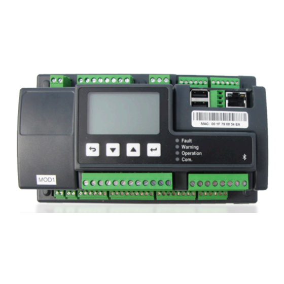
- Page 1 Lodam Condensing Unit Controller Modbus Interface Version LMC341 DIWE...
-
Page 2: Table Of Contents
Contents 1. Read this first ....................1.1. - Page 3 Modbus Interface manual LMC341 DIWE Page 3...
-
Page 4: Read This First
1. Read this first 1.1. Installation Before installation, the user should be thoroughly familiarized with this technical manual, especially The contents of this manual are subject to change with purposes, installation, settings and operation. without notice. Special care should be taken when installing and con- Lodam electronics holds the copyright to this user’s necting external equipment (sensor, high voltage etc.) manual. -
Page 5: General
Modbus Interface manual LMC341 DIWE 2. General 3. Definitions Lodam’s Condensing Unit Controller, LMC341 DIWE enable BEST BEST software you to gain total control of your condensing unit to deliver Hardware/electronics cooling to one or more evaporators – thereby optimizing your system to save energy, time and money. -
Page 6: How To
4. How to ... The end points, first and last controller on the string must have a 120 ohm termination resistor. All LMC341 DIWE controllers are grounded, the signal ground is not needed as PE (Protective Earth) is used as 4.1. -
Page 7: Connections
Modbus Interface manual LMC341 DIWE 5. Connections 5.2. Cable specification Communication is half duplex. • Use shielded, tinned copper, twisted-pair cable – twisted All LMC341 DIWE controllers have internally connected all the way to the controllers. signal ground and protective earth. The signal ground is • Max 200 m cable length. -
Page 8: Recommended Guidelines For Cable Routing
6. Setup 5.5. Recommended guidelines for cable routing • Signal, control and communication cables should be shielded with braided shielding and the shield connected Communication with the LMC341 DIWE is via Modbus to the earth connection – preferrable at the master (RTU). -
Page 9: Data Values, Scaling And Data Types
Modbus Interface manual LMC341 DIWE 6.2. Data values, scaling and data types Following is a description of used scaling and data types. Scale 1, 10 and 100 refers to where the decimal point is implied, as a decimal value can’t be transmitted via Modbus. -
Page 10: Functions
7. Functions For all registers apply that a more specific description of the parameters are to be found in the User manual for the LMC341 DIWE. The parameter names in brackets are the complete parameter name as listed in LMT or BEST. 7.1. -
Page 11: Inputs
Modbus Interface manual LMC341 DIWE Possible Register Name Default Description Address Values type LimTdis Unit None Tdis limiter is active Input register 1546 Scale 1 (Animation.LimTdis) unit8 0: Off 1: Active LimTfi Unit None Temp. FI limiter is active Input register 1547 Scale 1 (Animation.LimTfi) -
Page 12: Outputs
Possible Register Name Default Description Address Values type Oil_Sensor Unit Boolean Oil level failure Input register 1566 Scale 1 (Input.Oil_Switch) uint8 0: Off 1: Active SE-B1 Unit Boolean Compressor overheated Input register 1567 Scale 1 (Input.Cpr_OH) uint8 0: Ok 1: Failure Fan1_Fault Unit Boolean Fan1 failure... -
Page 13: Alarms
Modbus Interface manual LMC341 DIWE Possible Register Name Default Description Address Values type Fan 1 Input register 1590 Unit Boolean Scale 1 (Output.RE7) uint8 0: Off 1: On Unit Boolean Fan 2 Input register 1591 Scale 1 (Output.RE8) uint8 0: Off 1: On Unit Boolean Compressor running for ΔpII... - Page 14 Possible Register Name Default Description Address Values type Code1 Unit None Alarm number of most severe alarm Input register 1604 Scale 1 (Alarm.Code1) uint16 0: No alarm 100 – 40935: Alarm number Code2 Unit None Alarm number of less severe alarm Input register 1605 Scale 1...
-
Page 15: Control
Modbus Interface manual LMC341 DIWE 7.5. Control Parameters used to view and control operation of the LMC341 DIWE controller. Possible Register Name Default Description Address Values type Mode Unit None Overall unit mode Holding register 1632 Scale 1 (Control.PM_Mode) uint8 0: Off 1: On 2: Manual... -
Page 16: Modbus Sample Communication
8. Standards 7.6. Modbus sample communica- tion Note: The following sample is a general Modbus commu- The product is manufactured according to the following nication sample and is not for the LMC341 DIWE! standards. Request: 0b041000000e75a4 RoHS 2002/95/EC Response: 0b041cffff0000095008b0e4a- Low voltage 206/95/EC 80014000b000108e108f1ffff000f0002fff39f8e EMC 2004/108/EC... -
Page 17: Trouble Shooting
Modbus Interface manual LMC341 DIWE 9. Trouble shooting • Check if there is power to the LMC341 DIWE, range 15 - 30 VDC/12 – 24 VAC. • Check if Data+ and Data- wires have been switched. • Check if the communication node adress setting matches the selected. -
Page 18: Index
10. Index Alarms 13 Cable routing 8 Control 15 Data types and scaling 9 Definitions 5 Disposing 4 Functions 10 General 5 Inputs 11 Installation 4 Internally connected 7 Master controller 6 Modbus configuration 8 Modbus exception codes 9 Modbus function codes 9 Modbus sample communication 16 Outputs 12 Safety 4... -
Page 19: Notes
Modbus Interface manual LMC341 DIWE 11. Notes Page 19... - Page 20 As part of the BITZER Group we are backed by one of the world’s leading players in the refrigeration and air conditioning industry. This alliance provides us with extensive network and application knowhow and allows us to stay at the forefront of climate control innovation.
Need help?
Do you have a question about the Lodam LMC341 DIWE and is the answer not in the manual?
Questions and answers