
Summary of Contents for DencoHappel MultiMAXX HD
- Page 1 OPERATION MANUAL Decentral Systems Industry MultiMAXX ® Powerful Heating for Mixed-Air Application...
- Page 2 MultiMAXX HD DencoHappel product range PR-2007-0350-GB • Subject to modifications • R2-04/2016...
- Page 3 Profile, ceiling / wall, only heating with ceiling installation G4/ with differential pressure switch Secondary air louvre, wall installation, manual adjustment F7/ without differential pressure switch Secondary air louvre, actuator (230 V, on/off) for DencoHappel ® F7/ with differential pressure switch MATRIX...
-
Page 4: Table Of Contents
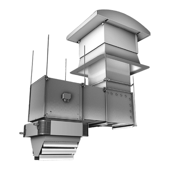
Connection diagrams ..................28 Terminal box or electrical switch box ............... 29 Connecting switch unit MC 300 or regulator by others ........30 ® Overview of the DencoHappel MATRIX control electronics ......32 Installing control panel ..................38 ® ............39 Electrical connection with DencoHappel MATRIX Network and shielding connection .............. - Page 5 MultiMAXX HD Technical Description and Scope of Supply Technical Description and Scope of Supply Fig. 3-1: Unit componets 1: Air discharge louvres 2: Heat exchanger 3: Fan module with inlet nozzle and terminal box 4: Fan with contact protection grille 5: Unit casing with plastic corners PR-2007-0350-GB •...
- Page 6 Technical Description and Scope of Supply MultiMAXX HD Unit in industrial casing Fig. 3-2 Unit in design / decorative casing Fig. 3-3 PR-2007-0350-GB • Subject to modifications • R2-04/2016...
-
Page 7: Safety And User Information
The unit heaters MultiMAXX HD are developed and manufactured in accordance with the state-of-the-art technological standards and established technical safety codes and regulations. The unit heaters MultiMAXX HD comply with the EU Machinery Safety Directive. The unit heaters MultiMAXX are reliable and satisfy strict quality standards. This product range combines advanced technology with a high level of user friendliness and ease of maintenance. -
Page 8: Labelling Of Safety Instructions
DAMAGE TO THE UNIT! Here you will find special information, rules and restrictions regarding the prevention of damage to the MultiMAXX HD. DANGER OF DAMAGE DUE TO STATIC DISCHARGE! While carrying out connections or adjustments on the MultiMAXX make sure that you discharge yourself statically before touchning PC boards and electrical components. -
Page 9: Safety-Conscious Working
Modifications and changes You must not change, add to or modify the MultiMAXX HD in any way. Any changes or modifications of the MultiMAXX HD will render the CE conformity and all warranty claims null and void. -
Page 10: Spare Parts
Also see „Disposal“ on page 47. 4.11 Personnel selection and qualification Every person authorised to work on or around the MultiMAXX HD must have read this entire operation manual and understood it completely – particularly the chapter on safety. -
Page 11: Technical Description
Technical Description Functional description of the unit The MultiMAXX HD unit heater consists of a heat exchanger and a fan with casing. The casing is made of galvanized steel sheet and can be supplied in RAL colour according to customer wishes. The air discharge opening can accommodate up to 13 different types of discharge louvres. -
Page 12: Unit Dimensions And Location Of Heat Exchanger Connecting Spogots
Technical Description MultiMAXX HD Unit dimensions and location of heat exchanger connecting spigots 5.2.1 Wall installation Unit designation Space for installation and Y, R maintenance Fig. 5-1 Unit designation Space for installation and U, M, W, O maintenance Fig. 5-2... - Page 13 MultiMAXX HD Technical Description Unit designation Space for installation and V, N, X, P maintenance Fig. 5-3 Size 1026 Model Model Model Model Y, R U, M, W, O V, N, X, P Y, R U, M, W, O V, N, X, P...
- Page 14 Technical Description MultiMAXX HD Unit designation Space for installation and Y, R maintenance Fig. 5-4 Unit designation V, N, X, P Space for installation and maintenance Fig. 5-5 Size 1026 Model Model Model Model Y, R V, N, X, P U, M, W, O...
- Page 15 MultiMAXX HD Technical Description 5.2.2 Ceiling installation Unit designation Y, R Fig. 5-6 Unit designation U, M, W, O Fig. 5-7 Size 1026 Model Model Model Model Y, R U, M, W, O V, N, X, P Y, R U, M, W, O V, N, X, P...
- Page 16 Technical Description MultiMAXX HD Unit designation V, N, X, P Fig. 5-8 Size 1026 Model Model Model Model Y, R U, M, W, O V, N, X, P Y, R U, M, W, O V, N, X, P Y, R...
- Page 17 MultiMAXX HD Technical Description Unit designation Y, R Fig. 5-9 Unit designation V, N, X, P Fig. 5-10 Size 1026 Model Model Model Model Y, R V, N, X, P U, M, W, O Y, R V, N, X, P U, M, W, O...
-
Page 18: Range Of Application
Weight data are indicated for units including basic discharge and 3-speed fan motor. NOTE! All other important information about unit capacity, weights, connections and sound power can be found in the „Data and Facts MultiMAXX HD - New Generation“. Range of application Unit heater Max. -
Page 19: Transportation And Storage
– For your own safety wear gloves and safety footwear when transporting the unit. Storage Protect the MultiMAXX HD unit from humidity and dirt. Store the unit on premises of class IE12, in accordance with the requirements EN 60 721-3-1. -
Page 20: Installation
Installation MultiMAXX HD Installation Load-bearing capacity of the installation site NOTE ON UNIT ASSEMBLY AND INSTALLATION! The assembly site must be vibration-free and suitable for permanently supporting the weight of the unit heater. If necessary, the approval of a structural engineer or archi- tect has to be received. -
Page 21: Wall Installation
MultiMAXX HD Installation Size Distance to ceiling A, not less (mm) Distance between units in ceiling installation (see Fig. 7-2) In order to provide favourable surface coverage in the occupied zone we recommend the following distances between units: 6 - 12 m 3 - 6 m Fig. - Page 22 Installation MultiMAXX HD Minimum distance from wall A (see Fig. 7-3) It is necessary to keep the minimum distance to allow sufficient air circulation and provide sufficient access for maintenance. Size Distance to wall A, not less (mm) 10 - 15 m...
-
Page 23: Installing The Unit
MultiMAXX HD Installation Wall installation: – of the circulating air unit with suspension „Modular“ (ZHx.550x) is specified in Fig. 7-6 and – of the mixed air unit with suspension „Modular“ is specified in Fig. 7-8. Installing the unit NOTE! It is necessary to install the units in a safe, reliable and visually acceptable way. For these reasons, it is recommended to use manufacturer’s suspensions. - Page 24 Installation MultiMAXX HD Fig. 7-5 Fig. 7-6 PR-2007-0350-GB • Subject to modifications • R2-04/2016...
- Page 25 MultiMAXX HD Installation 1: LPWW register with Cu/Cu heat exchanger, left connection, external thread, 3-stage diagonal fan, integrated controls and design casing 2: Bag filter F7 3: Mixed air damper, type 3 4: Flexible connection 5: Mounting kit for ceiling suspension...
-
Page 26: Medium Connections
Medium Connections MultiMAXX HD Medium Connections The supply and return piping should be run in such a way as to prevent mechanical stress and without placing a strain on the heat exchanger with sufficient clearance around the unit to allow for maintenance and repair operations. -
Page 27: Electrical Connections
Electrical Connections Electrical Connections DANGER OF ELECTRICAL CURRENT! The electrical installation of the MultiMAXX HD unit heaters must only be car- ried out by qualified electricians in observance of this operation manual and the current regulations: – VDE regulations, including safety regulations –... -
Page 28: Terminal Box Or Electrical Switch Box
Electrical Connections MultiMAXX HD Terminal box or electrical switch box Depending on the model version the MultiMAXX HD units are supplied either with: – plastic terminal box or – steel sheet electrical switch box. Steel sheet electrical switch box Plastic terminal box Installed by the manufacturer Fig. -
Page 29: Connecting Switch Unit Mc 300 Or Regulator By Others
On 2-speed motors connection shall be carried out in the left rotary field! DANGER OF ELECTRIC CURRENT! Before opening the connection box the MultiMAXX HD unit heater must be dis- connect from the power supply in all poles. •... - Page 30 Electrical Connections MultiMAXX HD 3-speed operation mode – 3-stage switch (MC303/MC333) – connection cable: 9+РЕ=10 wires – screened line: 2 TC connecting wires TK TK 2V 2U 1-speed operation mode – 1-stage switch (MC301/MC331) – connection cable: 3+РЕ=4 wires TK TK 2V 2U –...
- Page 31 MultiMAXX HD Electrical Connections Overview of MATRIX control electronics The MATRIX control electronics are built into the electrical control box.The following overview illustrates the different control PCBs. In order for you to be able to make the necessary connections, the following PCB layouts illustrate the controller type installed in each case.You can also check the controller type (e.g.
- Page 32 Electrical Connections MultiMAXX HD 9.4.2 Controller type MATRIX 2002 and MATRIX 3002 MATRIX MATRIX 2002 3002 4002 4002+IO 2002 3002 4002 4002+IO – Power supply – Power supply – Secondary air louvre – Secondary air louvre (connection to MATRIX 3000) –...
- Page 33 MultiMAXX HD Electrical Connections 9.4.3 Controller type MATRIX 4002 and MATRIX 4002+IO MATRIX MATRIX 2002 3002 4002 4002+IO 2002 3002 4002 4002+IO – Power supply – Secondary air louvre – Actuator of mixed air damper – Control panel connection – Power supply –...
- Page 34 Electrical Connections MultiMAXX HD 9.4.4 Controller type MATRIX 2003 and MATRIX 3003 MATRIX MATRIX 2003 3003 4003 4003+IO 2003 3003 4003 4003+IO – Power supply – Power supply – Secondary air louvre – Secondary air louvre (connection to MATRIX 3000) –...
- Page 35 MultiMAXX HD Electrical Connections 9.4.5 Controller type MATRIX 4003 and MATRIX 4003+IO MATRIX MATRIX 2003 3003 4003 4003+IO 2003 3003 4003 4003+IO – Power supply – Secondary air louvre – Power supply – Actuator of mixed air damper – Secondary air louvre –...
- Page 36 Electrical Connections MultiMAXX HD 9.4.6 Controller type MATRIX 4004 and MATRIX 4004+IO MATRIX MATRIX 4004 4004+IO 4004 4004+IO – Power supply – Power supply – Secondary air louvre – Secondary air louvre – Actuator of mixed air damper – External valve –...
-
Page 37: Installing Control Panel
MultiMAXX HD Electrical Connections Installing control panel All control panels are supplied in IP54 protection class together with a loose external room temperature sensor. NOTE! The location where the sensor is fitted is crucial for the temperature in the room to be regulated precisely. -
Page 38: Electrical Connection With Dencohappel Matrix
Electrical Connections MultiMAXX HD Electrical connection with MATRIX 9.6.1 Connecting mains voltage for units with 230 V operating voltage MATRIX 2001 3001 4004 4004+IO Pos. 1: Input 230 V AC / 50 Hz, Fusing by others max. B 10 A Pos. - Page 39 MultiMAXX HD Electrical Connections 9.6.2 Connecting mains voltage for units with 400 V operating voltage MATRIX 2002 3002 4002 4002+IO 2003 3003 4003 4003+IO Pos. 1: Input 400 V AC / 50 Hz, Fusing by others max. B 16 A Pos.
- Page 40 Electrical Connections MultiMAXX HD MATRIX 200x 300x 400x 400x+IO Control panel connection – air treatment unit (without valves) Control panel MATRIX OP21 can be connected only to units equipped with MATRIX 200х. • Connect the control cables in accordance with the wiring diagram.
- Page 41 MultiMAXX HD Electrical Connections MATRIX 200x 300x 400x 400x+IO Connecting first unit with MATRIX 300х and further units with MATRIX 200х Units with MATRIX 300x can be connected to units equipped with MATRIX 200х. • Connect the control cables in accordance with the wiring diagram.
- Page 42 Electrical Connections MultiMAXX HD Connecting control panel and air treatment unit Control panels with MATRIX ОР30 - MATRIX ОР51 can only be connected with units, equipped with MATRIX 300х/400х. • Connect the bus line in accordance with the wiring diagram.
- Page 43 MultiMAXX HD Electrical Connections 9.6.5 Connecting outside sensor (alternative) MATRIX 200x 300x 400x 400x+IO 1: Connection cable (see note on page 40) & • Connect the outside sensor according to the wiring diagram. Fig. 9-18: Connecting outside sensor (alternative) 9.6.6 Connecting inlet sensor (option)
- Page 44 Electrical Connections MultiMAXX HD 9.6.9 Connecting operation and fault messaging MATRIX 200x 300x 400x 400x+IO The controller PCB enables to tap status and fault messa- ges using a potential free contact. The contact load at 230 V AC amounts to a maximum of 4 A ohmic / 2 A inductive.
- Page 45 MultiMAXX HD Electrical Connections 9.6.11 Connecting functional inputs and outputs MATRIX 200x 300x 400x 400x+IO Functional inputs Heating Functional inputs can be assigned with different functions. Jumper – Normal operation Cooling – Economy mode operation – Free operation mode Jumper (The functions of these operation modes can be programmed using the service software MATRIX.PC)
- Page 46 Electrical Connections MultiMAXX HD • Connect the secondary air louvres according to the wiring diagram. Fig. 9-26: Connecting secondary air louvres 9.6.13 Connecting valve actuator MATRIX 200x 300x 400x 400x+IO • Connect the valve actuator according to the wiring diagram.
- Page 47 MultiMAXX HD Electrical Connections 9.6.16 Connecting mixed air damper MATRIX 200x 300x 400x 400x+IO • Connect the mixed air damper according to the wiring diagram. – Terminal 133 closes mixed air damper – Terminal 134 opens mixed air damper – Signal tapping of potentiometer has to be made on terminal 02, external tapping is arbitrary.
-
Page 48: Network And Shielding Connection
Electrical Connections MultiMAXX HD Network and shielding connection This section contains information about the MATRIX.Net and the correct network setup. The MATRIX.Net is a network through which various components of the control system (network users) are connected via a data bus. The bus enables to exchange all infor- mation required for control and regulation between the users. - Page 49 The data of the MATRIX.LON module are assigned as part of the LON configuration. The MATRIX.V module is assigned to this group via the group address switch – refer to the “Commissioning and Testing” Chapter in the operation manual for DencoHappel ®...
- Page 50 The MATRIX.V, MATRIX.RF and MATRIX.EM modules are assigned to this group via the group address switch – refer to the “Commissioning and Testing” Chapter in the ® operation manual for DencoHappel MATRIX global modules. NOTE! The combination of units with MATRIX 3000 and units with MATRIX 2000 sys- tems is permitted in this group set-up –...
- Page 51 MultiMAXX HD Electrical Connections 9.7.2 Network structure A network can consist of one or several groups (up to 16). Global modules can also be integrated into the network. The network structure/network topology of MATRIX.Net should be linear – see “Network topologies” on page 53.
- Page 52 Electrical Connections MultiMAXX HD 9.7.3 Network topologies The MATRIX.Net can be set in a line structure and a line structure with stub line. All units fitted with MATRIX system can access this data bus. The data bus must be terminated at both physical ends to avoid reflections which can interfere with data transfer.
- Page 53 MultiMAXX HD Electrical Connections 9.7.5 Line structure with stub line The illustration shows the setup of the MATRIX.Net with line and stub line structure. A sample connection of a control panel via a stub line in multiple groups is illustrated. The maximum allowed stub line length amounts to 25 m.
- Page 54 Electrical Connections MultiMAXX HD 9.7.6 Network set up Data transfer cable For setting up the MATRIX.Net use only data transfer cable certified according to DIN 19245 T3 and EN 50170 with twisted pair cores and braided shield. RECOMMENDATION We recommend the following data transfer cable: Producer: HELUKABEL Type: CAN-BUS flexible 2 x 2 x ...
-
Page 55: Commissioning
10.1 Safety inspection 10.1.1 Requirements before commissioning: – The entire system to which MultiMAXX HD has been installed both mechanically and electrically. – The system, and thus the MultiMAXX HD is powered down. – All medium pipes have been rinsed and are free from residues and foreign bodies. - Page 56 Commissioning MultiMAXX HD 10.1.2 Checks before commissioning: • Check that the MultiMAXX HD is correctly mounted. • Open the valve on the piping. • If the medium lines/heat exchanger are empty, competent personnel should refill and air vent them. Make sure the air venting is completed to avoid air bubbles in the heat exchanger.
-
Page 57: Terminating Resistors
MultiMAXX HD Commissioning 10.2 Terminating resistors MATRIX 200x 300x 400x 400x+IO There are no terminating resistors on the unit printed circuit boards of the MATRIX 200x control system. On the control panel the terminating resistors have to be switched on or off only if a network is established through the MATRIX.Net to other unit groups or additional modules, such as a clock module, or to input and output modules. - Page 58 Commissioning MultiMAXX HD MATRIX 200x 300x 400x 400x+IO There are terminating resistors on the unit printed circuit boards of the MATRIX 300x/400x control system. Switching on the terminating resistors at the beginning and end of the line: • Turn the DIP switch on both users (e.g. control panels, unit PCBs or modules) to “ON”.
-
Page 59: Setting Address
MultiMAXX HD Commissioning Setting address 10.3 MATRIX 200x 300x 400x 400x+IO The unit PCBs of the MATRIX 200x control system do not contain any address selection switches. The appropriate group address must be assigned on the control panel. Single group (without networking multiple unit groups) •... - Page 60 Commissioning MultiMAXX HD MATRIX 2001 3001 The appropriate group address must be assigned on the control panel and the units of a group. Single group (without networking multiple unit groups) • On the control panel, set the address “0” (manufacturer's default setting).
-
Page 61: Setting Limitation Functions
MultiMAXX HD Commissioning Setting limitation functions 10.4 MATRIX 200x 300x 400x 400x+IO Limitation values of the supply air temperature can be set for heating and cooling oper- ation. – Heating operation: Minimum and maximum limitation (limitation type rigid or sliding) –... - Page 62 Commissioning MultiMAXX HD Minimum heating limitation (sliding): The temperature can fall below the set minimum limitation temperature value if the actual room temperature value lies above the setpoint by the amount that results from the room temperature deviation multiplied by the influence coefficient.
-
Page 63: Switching The Unit
MultiMAXX HD Commissioning Switching the unit 10.5 DANGER OF ELECTRICAL CURRENT! The electrical control box is open. Direct interventions in the electrical switch box are not permitted! Before completeting work on the air treatment unit, ensure that the electrical switch box is properly closed. -
Page 64: Checking Data Connection
Commissioning MultiMAXX HD Checking data connection 10.6 DANGER OF ELECTRICAL CURRENT! Before correcting an error in the data connection, power the entire system down. Ensure that the unit is secured against being switched back on at an appropriate point of the on-site power supply. -
Page 65: Checking Control Inputs And Outputs
MultiMAXX HD Commissioning Checking control inputs 10.7 and outputs The MATRIX 300x/400x control system has control inputs or outputs. When checking the control inputs and outputs proceed from the configuration made by the manufacturer. Refer to the unit connection diagram (see inside cover of the unit connection box) for the relevant controller function. - Page 66 Commissioning MultiMAXX HD 10.7.2 Enabling external exhaust control MATRIX 200x 300x 400x 400x+IO Enabling procedure • Turn the unit on and adjust the setpoint as required until the fan is running. • Confirm the mixed air damper control. The outside air damper opens and the possibly connected exhaust fan switches on.
-
Page 67: Functional Possibilities
MultiMAXX HD Commissioning 10.8 Functional possibilities 10.8.1 Fan mode The behaviour of the fan control depends on the configured control type and operation mode on the selected control panel. The following fan modes can be set: – Manual fan control –... - Page 68 Commissioning MultiMAXX HD 10.8.2 Valves Depending on the selected controller equipment, the integrated valve controller supports valves with on/off control or modulating behaviour. The valves can be controlled in the following modes: – Heating – Cooling – Heating or cooling –...
- Page 69 MultiMAXX HD Commissioning 10.8.6 Stand by mode The stand by mode is only available in room temperature control mode. This does not regulate the temperature to a fixed setpoint, but instead to a pre-set setpoint range. This setpoint range can only be changed using the MATRIX.PC service software. The stand by mode is active if a room temperature sensor is connected but no room temperature setpoint, i.e.
- Page 70 Commissioning MultiMAXX HD 10.8.10Secondary air grille The secondary air grille delivers the air treated by the unit heater to the air conditioned area in an optimal way. The secondary air grille control system changes the angle at which the particular amount of air is discharged (fan speed) at current temperatures.
- Page 71 MultiMAXX HD Commissioning The following applies to the fan speed and the resulting discharge speed: - at low discharge speed, the air is directed down at a steep angle - at high discharge speed, the air is directed laterally at a blunt angle After the fan is switched off, the secondary air grille moves after approx.
-
Page 72: Cleaning And Maintenance
Cleaning and Maintenance MultiMAXX HD 11 Cleaning and Maintenance 11.1 Cleaning DANGER OF ELECTRICAL CURRENT! Power the unit down before cleaning. Ensure that the unit is secured against being switched back on at an appropriate point of the on-site power supply. - Page 73 MultiMAXX HD Cleaning and Maintenance The maintenance of the unit may only be carried out by the DencoHappel service company or refrigeration engineer! During maintenance work all safety relevant codes and practices shall be observed. It is recommended to conclude a service con- tact with a service company.
-
Page 74: Troubleshooting
Troubleshooting MultiMAXX HD 12 Troubleshooting Fault Possible reason Remedy Fan is not running Mains supply unavailable or Check power supply, fuse and connection Fan isolator is switched on faulty control fusing Signal LED does not light up Cable connection interrupted... -
Page 75: Dismantling And Disposal
MultiMAXX HD Dismantling and Disposal 13 Dismantling and Disposal ENVIRONMENTAL DAMAGE! Only appropriately trained staff may dismantle and dispose of the unit! 13.1 Dismantling To dismantle the unit, proceed as follows: ELECTRICAL HAZARD! When carrying out any decommissioning and dismantling work on the unit, isolate all power supply connections, ensure they cannot be switched on again unintentionally and verify that they have been disconnected. - Page 76 DencoHappel is a global company with expertise in air treatment, air conditioning and air filtration. Our nearest sales and service teams will be glad to discuss ideas and develop creative and effective solutions with you. www.dencohappel.com...
Need help?
Do you have a question about the MultiMAXX HD and is the answer not in the manual?
Questions and answers