Table of Contents
Advertisement
Quick Links
I
NSTALLATION
A/GPD 14 SEER "M" SERIES - S
D
F
G
-E
UAL
UEL
AS
Affix this manual and Users Information Manual
adjacent to the unit.
ATTENTION INSTALLING PERSONNEL
Prior to installation, thoroughly familiarize yourself with this
Installation Manual. Observe all safety warnings. During installa-
tion or repair, caution is to be observed.
It is your responsibility to install the product safely and to edu-
cate the customer on its safe use.
RECOGNIZE THIS SYMBOL
AS A SAFETY PRECAUTION.
These installation instructions cover the outdoor installation
of single package gas electric heating and cooling units. See
the Specification Sheet applicable to your model* for
information regarding accessories.
*NOTE: Please contact your distributor or our website for
the applicable Specifications Sheets referred to in this manual.
This Forced Air Central Unit Design Complies With Requirements
Embodied in The American National Standard / National
Standard of Canada Shown Below.
ANSI Z21.47•CSA-2.3 Central Furnaces
*NOTE: Please contact your distributor or our website for
the applicable Specification Sheet referred to in this manual.
IO-407K
07/2018
is a registered trademark of Maytag Corporation or its related companies and is used under license. All rights reserved.
I
NSTRUCTIONS
H
& C
LECTRIC
EATING
Goodman Manufacturing Company, L.P.
5151 San Felipe, Suite 500, Houston, TX 77056
www.goodmanmfg.com or www.amana-hac.com
© 2011-2018 Goodman Manufacturing Company, L.P.
P
INGLE
ACKAGE
U
OOLING
NITS
O
NLY PERSONNEL THAT HAVE BEEN TRAINED TO INSTALL
(
REPAIR
HEREINAFTER
SHOULD SERVICE THE EQUIPMENT
FOR ANY INJURY OR PROPERTY DAMAGE ARISING FROM IMPROPER SERVICE OR
SERVICE PROCEDURES
FOR ANY INJURY OR PROPERTY DAMAGE WHICH MAY RESULT
JURISDICTIONS THAT REQUIRE ONE OR MORE LICENSES TO SERVICE THE EQUIPMENT
SPECIFIED IN THIS MANUAL
. I
EQUIPMENT
MPROPER INSTALLATION
THE EQUIPMENT SPECIFIED IN THIS MANUAL
SERVICE OR REPAIR THE EQUIPMENT SPECIFIED IN THIS MANUAL WITHOUT PROPER
TRAINING MAY RESULT IN PRODUCT DAMAGE
.
INJURY OR DEATH
Cancer and Reproductive Harm-
www.P65Warnings.ca.gov.
, "
")
SERVICE
THE EQUIPMENT SPECIFIED IN THIS MANUAL
. T
HE MANUFACTURER WILL NOT BE RESPONSIBLE
. I
,
F YOU SERVICE THIS UNIT
YOU ASSUME RESPONSIBILITY
,
ONLY LICENSED PERSONNEL SHOULD SERVICE THE
,
,
ADJUSTMENT
SERVICING OR REPAIR OF
,
OR ATTEMPTING TO INSTALL
,
PROPERTY DAMAGE
WARNING
,
,
ADJUST
SERVICE OR
. I
,
N ADDITION
IN
,
,
ADJUST
,
PERSONAL
Advertisement
Table of Contents

Summary of Contents for Intertek A/GPD1424 Series
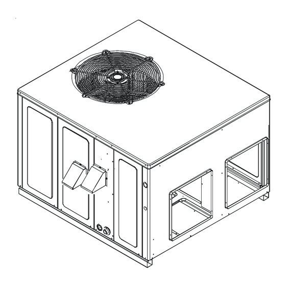
- Page 1 NSTALLATION NSTRUCTIONS A/GPD 14 SEER “M” SERIES - S INGLE ACKAGE & C LECTRIC EATING OOLING NITS Affix this manual and Users Information Manual adjacent to the unit. ATTENTION INSTALLING PERSONNEL Prior to installation, thoroughly familiarize yourself with this Installation Manual. Observe all safety warnings. During installa- tion or repair, caution is to be observed.
-
Page 2: Table Of Contents
INDEX (continued) INDEX CONDENSATE DRAIN ........... 14 ......... 14 ONDENSATE RAIN ONNECTION TO THE INSTALLER ............. 2 NORMAL SEQUENCES OF OPERATION ......14 TO THE OWNER ............2 HEAT PUMP OPERATION ..........14 SHIPPING INSPECTION ..........2 ......... 14 UTDOOR HERMOSTAT SAFETY INSTRUCTIONS .......... - Page 3 FIRE OR EXPLOSION HAZARD Failure to follow the safety warnings exactly could result in serious injury, death or property damage. Never test for gas leaks with an open flame. Use a commercially available soap solution made specifically for the detection of leaks to check all connections.
- Page 4 AVERTISSEMENT RISQUE D'INTOXICATION AU MONOXYDE DE CARBON MONOXIDE POISONING HAZARD CARBONESi les étapes décrites ci-dessous ne sont pas Failure to follow the steps outlined below for each suivies pour chacun des appareils raccordés au système appliance connected to the venting system being de ventilation au moment de sa mise en marche, cela placed into operation could result in carbon monoxide peut entraîner une intoxication au monoxyde de...
-
Page 5: Ordering Parts
RISQUE D'EMPOISONNEMENT AU MONOXYDE DE CARBONE Advertencia especial para la instalación de calentadores ó manejadoras de aire en áreas cerradas como estacionamientos ó cuartos de servicio. Cette ventilation est nécessaire pour éviter le danger d'intoxication Las emisiones de monóxido de carbono pueden circular a través au CO pouvant survenir si un appareil produisant du monoxyde del aparato cuando se opera en cualquier modo. -
Page 6: Pre-Installation Checks
PRE-INSTALLATION CHECKS Before attempting any installation, the following points should be considered: • Structural strength of supporting members • Clearances and provision for servicing • Power supply and wiring • Air duct connections • Drain facilities and connections • Gas piping and connections •... -
Page 7: Rooftop Installations Only
OOFTOP NSTALLATIONS NOTE: To ensure proper condensate drainage, unit must be installed in a level position. • To avoid possible property damage or personal injury, the roof must have sufficient structural strength to carry the weight of the unit(s) and snow or water loads as required by local codes. Consult a structural engineer to determine the weight capabilities of the roof. -
Page 8: Rigging Details
RIGGING DETAILS Refer to the Unit Installation Instructions for proper unit installation. Curbing must be installed in compliance with the National Roofing Contractors Association Manual. Lower unit carefully onto roof mounting curb. While rigging unit, center of gravity will cause condenser end to be lower than supply air end. - Page 9 Natural Gas Connection Natural Gas Capacity of Pipe in Cubic Feet of Gas Per Hour (CFH) Refer to the Proper Piping Practice drawing for the general layout at the unit. The following rules apply: Nominal Black Pipe Size (inches) Length of 1.
- Page 10 Propane Gas Installations IMPORTANT NOTE: Propane gas conversion kits must be installed to convert units to propane gas. Refer to the gas piping section for the correct LP kit for conversion. All propane gas equipment must conform to the safety stan- dards of the National Board of Fire Underwriters (See NBFU Manual 58).
-
Page 11: Wiring
WIRING NOTE: All wiring should be made in accordance with the National Electrical Code. Consult your local Power Company to determine the availability of sufficient power to operate the unit. Check the voltage, frequency, and phase at the power supply to ensure it corresponds to the unit’s RATED VOLTAGE REQUIREMENT. In accordance with the N.E.C. -
Page 12: Circulating Air And Filters
For unit protection, use a fuse or HACR circuit breaker that is in excess of the circuit ampacity, but less than or equal to the maximum overcurrent protection device. DO NOT EXCEED THE MAXIMUM OVERCURRENT DEVICE SIZE SHOWN ON UNIT DATA PLATE. All line voltage connections must be made through weather- proof fittings. -
Page 13: Filters
The supply duct from the unit through a wall may be installed without clearance. However, minimum unit clearances as shown in the appendix must be maintained. The supply duct should be provided with an access panel large enough to inspect the air chamber downstream of the heat exchanger. -
Page 14: Condensate Drain
CONDENSATE DRAIN DRAIN CONNECTION ONDENSATE RAIN ONNECTION A 3/4” NPT drain connection is supplied for condensate piping. An UNIT 2" MINIMUM external trap must be installed for proper condensate drainage. FLEXIBLE TUBING-HOSE 3" MINIMUM OR PIPE NORMAL SEQUENCES OF OPERATION A POSITIVE LIQUID HEAT PUMP OPERATION SEAL IS REQUIRED... -
Page 15: Defrost Cycle
EFROST YCLE NOTE: The defrost board is equipped with a jumper for SmartShift™ defrost technology operation. This operation turns the compressor off for 30 seconds at defrost initiation and termination. The unit is factory shipped for SmartShift™ defrost technology operation. To operate unit at rated efficiencies, move the jumper on the defrost board from “DLY” to “NORM”. During operation the power to the circuit board is controlled by a temperature sensor, which is clamped to a feeder tube entering the outdoor coil. -
Page 16: Start-Up, Adjustments, And Checks
START-UP, ADJUSTMENTS, AND CHECKS / LP) EATING TART ATURAL This unit is equipped with an electronic ignition device to automatically light the main burners. It also has a power vent blower to exhaust combustion products. On new installations, or if a major component has been replaced, the operation of the unit must be checked. Check unit operation as outlined in the following instructions. - Page 17 Gas Supply And Manifold Check Gas supply pressure and manifold pressure with the burners operating must be as specified on the rating plate. Gas Inlet Pressure Check Gas inlet pressure must be checked and adjusted in accordance to the type of fuel being consumed. With Power And Gas Off: 1.
- Page 18 Temperature Rise Check Check the temperature rise through the unit by placing thermometers in supply and return air registers as close to the unit as possible. Thermometers must not be able to sample temperature directly from the unit heat exchangers, or false readings could be obtained.
-
Page 19: Cooling Start - Up
OOLING TART NOTE: Check all manual reset limit controls in heating circuit if cooling mode does not operate. Compressor Protection Devices The compressor includes components which are designed to protect the compressor against abnormal operating conditions. Refrigerant Charge Check (Units with Fixed Orifice Devices) Design superheat &... -
Page 20: Main Burner Flame
3. Remove the flue from the induced draft blower and the collector box cover from the partition panel. 4. The primary heat exchanger tubes can be cleaned using a round wire brush attached to a length of high grade stainless steel cable, such as drain cleanout cable. -
Page 21: Appendix
APPENDIX... -
Page 22: Troubleshooting
TROUBLESHOOTING DIAGNOSTIC CHECK CHECK STATUS LED - RED NORMAL OPERATION CHECK INPUT POWER NO POWER OR INTERNAL CONTROL CHECK FUSE(S) FAULT GAS FLOW GAS PRESSURE 1 FLASH IGNITION FAILURE GAS VALVE FLAME SENSOR CHECK PRESSURE SWITCH 2 FLASHES CHECK TUBING PRESSURE SWITCH OPEN CHECK VENT MOTOR PRESSURE SWITCH CLOSED... -
Page 23: Ignition Control Diagnostic Indicator Chart
IGNITION CONTROL DIAGNOSTIC INDICATOR CHART Red Light Signal Refer to Abnormal Heating or Cooling Operation Sections of this Manual Internal Control Failure 1 Flash External Lockout 2 Flashes Pressure Switch Stuck Open 3 Flashes Pressure Switch Stuck Closed 4 Flashes Thermal Protection Device Open 5 Flashes Flame Detected with Gas Valve Closed... -
Page 24: Unit Dimensions
UNIT DIMENSIONS FLUE EXHAUST HOOD 18 7/16 FLUE EXHAUST 1 3/8 5 1/2 7 15/16 SUCTION/LIQUID PRESSURE PORTS 2 3/4 BEHIND COMPRESSOR ACCESS PANEL COMBUSTION AIR INTAKE RETURN HEAT EXCHANGE ACCESS PANEL 4 3/4 GAS SUPPLY ENTRANCE SUPPLY CONDENSATE DRAIN CONNECTION 3/4"... -
Page 25: Wiring Diagram
[A/G]PD14[24-48]***M41** WIRING DIAGRAM SEE NOTE 7 S R C SEE NOTE 8 COMP SEE NOTE 4 RCCF C-RV R-PS1 O-RV LVDR BL/PK BL/PK HVDR R-DFT P1 - PIN # 1 SEE NOTE 2 P1 - PIN # 6 P1 - PIN # 8 P1 - PIN # 3 P1 - PIN # 5 P1 - PIN # 2... - Page 26 [A/G]PD14[24-48]***M41** WIRING DIAGRAM SUPPLY VOLTAGE 208-230/1/6 0 COMPONENT LEGEND SEE NOTE 7 AUXILLARY LIMIT SWITCH FACTORY WIRING CONTACTOR CRANKCASE HEATER LINE VOLTAGE SEE NOTE 8 CRANKCASE HEATE R SWITCH LOW VOLTAGE CONDENSER MOTOR COMP OPTIONAL HIGH COMP COMPRESSOR RCCF VOLTAGE DEFROST CONTROL BOARD DEFROST THERMOSTA T FIELD WIRING...
-
Page 27: Minimum Clearances
MINIMUM CLEARANCES Clearance in accordance with local installation codes, the requirements of the gas supplier and the manufacturer’s installation instructions. Dégaugement conforme aux codes d’installation locaux, aux exigences du fournisseur de gaz et aux instructions d’installation du fabricant NOTE: Roof overhang should be no more than 36". RECOMMENDED FILTER SIZES UNIT 2 Ton... - Page 28 THIS PAGE LEFT INTENTIONALLY BLANK...
-
Page 29: B Lower P Erformance D Ata
BLOWER PERFORMANCE DATA *PD1424060M41A* - Rise Range: 35° - 65° E.S.P Cooling Speed Cooling Speed Cooling Speed Stage Heating Speed Stage Heating Speed WATTS RISE WATTS RISE WATTS WATTS WATTS 1048 *PD1424070M41B* - Rise Range: 35° - 65° F E.S.P Cooling Speed Cooling Speed Cooling Speed... - Page 30 BLOWER PERFORMANCE DATA *PD1436080M41A* - Rise Range: 35° - 65° Cooling Speed Cooling Speed Cooling Speed Stage Heating Speed Stage Heating Speed E.S.P WATTS RISE WATTS RISE WATTS WATTS WATTS 1276 1317 1317 1453 1238 1269 1269 1405 1206 1221 1221 1357 1164...
- Page 31 BLOWER PERFORMANCE DATA *PD1442115M41B* - Rise Range: 45° - 75° F E.S.P Cooling Speed Cooling Speed Cooling Speed Stage Heating Speed Stage Heating Speed WATTS RISE WATTS RISE WATTS WATTS WATTS 1090 1286 1354 1501 1609 1025 1225 1296 1446 1556 1165 1237...
-
Page 32: Start-Up Checklist
Start-up Checklist *Store in job file Air Conditioning & Heating Date: ___________________________________ Location: __________________________________________ Model Number: ___________________________________ __________________________________________ Serial Number: ___________________________________ __________________________________________ Technician: ___________________________________ Unit #: __________________________________________ Pre Start-Up (Check each item as completed) Verify all packaging material has been removed. Remove all shipping brackets per installation instructions. - Page 33 Start-up Checklist Air Conditioning & Heating Start-Up (Insert the values as each item is completed.) ELECTRICAL Supply Voltage L1 - L2 L2 - L3 L3 - L1 Circuit 1 Compressor Amps Circuit 2 Compressor Amps Blower Amps Condenser Fan Amps Fan 1 Fan 2 Fan 3...
- Page 34 THIS PAGE LEFT INTENTIONALLY BLANK...
- Page 35 THIS PAGE LEFT INTENTIONALLY BLANK...
- Page 36 CUSTOMER FEEDBACK We are very interested in all product comments. Please fill out the feedback form on one of the following links: Goodman® Brand Products: (http://www.goodmanmfg.com/about/contact-us). Amana® Brand Products: (http://www.amana-hac.com/about-us/contact-us). You can also scan the QR code on the right for the product brand AMANA®...
Need help?
Do you have a question about the A/GPD1424 Series and is the answer not in the manual?
Questions and answers
Wiring diagram for Intertek mod# BL-E30E outdoor light