
Summary of Contents for siat ProWrap Series
- Page 1 Semi-automatic pallet wrapper ProWrap Operation and maintenance manual Translation of the “ORIGINAL INSTRUCTIONS” SBC0035151 Code ed. 05-2018 - rev. 1...
- Page 2 No part of this publication may be reproduced without the written consent of the Manufacturer. Pursuing a policy of continuous improvement, the Manufacturer reserves the right to change this document without notice, provided that such changes do not create risks to safety.
-
Page 3: Table Of Contents
Summary Safety information Purpose of the manual ......................3 Glossary of the terms ......................3 Attached documentation ......................4 General safety warnings ......................5 Safety Warnings for Handling and Installation ................ 5 Safety Warnings for Operation and Use.................. 6 Safety Manager Obligations ....................7 Safety Warnings on Misuse..................... - Page 4 Tension adjustment of film ....................49 Cleaning and replacement of brake disc ................50 Replacing the outer surface of roller .................. 51 Reel holding carriage (FM) Reel holding carriage (FM) ....................52 Main components ......................52 Film Coil Feeding ....................... 53 Cleaning and replacement of brake disc ................
-
Page 5: Safety Information
Safety information Purpose of the manual – The purpose of the manual is to inform and train operators so that they can inter- act with the machine in SAFE CONDITIONS. – Its aim is also to prevent risks, to reduce the social costs resulting from accidents and damage to the health of people, property and to the environment. -
Page 6: Attached Documentation
Safety information – Operating Stop: state that does not cut off power supply to the actuators, but ensures control system monitoring in safe conditions. – Size change: a set of interventions to be carried out before beginning to work with specifications different with respect to the ones previously in use. –... -
Page 7: General Safety Warnings
Safety information General safety warnings – The machine has been designed and built with all the precautionary measures aimed at minimising the possible risks over its expected life cycle. – Tampering with and bypassing the safety devices may lead to severe risks for the Operators. -
Page 8: Safety Warnings For Operation And Use
Safety information – The packs being shipped must be properly fastened to the means of transport in order to ensure safe conditions during transfer and the integrity of their contents. – During some handling phases, the support of one or more operators may be re- quired;... -
Page 9: Safety Manager Obligations
Safety information – Ensure the area around the machine, especially the control post, is ALWAYS unobstructed and in good condition to minimize the risks for the Operator. – According to the type of operation to carry out, wear the Personal Protective Equipment listed in the “Instructions for use”... -
Page 10: Safety Warnings On Residual Risks
Safety information – DO NOT replace the components with non-genuine spare parts or other compo- nents with different design and manufacturing specifications. – DO NOT dump in the environment any materials, polluting liquids and mainte- nance waste generated during the operations. Dispose of them according to the regulations in force. -
Page 11: Safety Warnings For The Electrical Equipment
Safety information – The use of similar but not genuine spare parts can lead to non-compliant repairs, impaired performance and economic damage. – Use the lubricants (oils and greases) recommended by the Manufacturer or lubri- cants of equivalent chemical and physical characteristics. –... -
Page 12: Safety Warnings For The Environmental Impact
Safety information Safety warnings for the environmental impact Each organization is responsible for implementing procedures aimed at iden- tifying, evaluating and controlling the environmental impact of its own activi- ties (products, services, etc.). – Procedures for identifying significant environmental impact must take account of the factors listed. -
Page 13: Safety And Information Symbols
Safety information Safety and information symbols – The information signals may be of different shapes and colours, to indicate dan- gers, obligations, prohibitions and indications. – The illustrations show the shapes of the signals that can be applied, with the function indicated –... - Page 14 Safety information English language Operation and maintenance manual...
-
Page 15: Technical Specifications
Technical Specifications general description of the machine The semi-automatic wrapper series “ProWrap” is designed to secure products loaded on pallets using stretch film. – To wrap loads, commercially available reels of stretch film are used. – The products to be wrapped must be contained in packages (cases, containers for liquids, etc.) having a regular shape or in any case, such as to allow for stable palletising. - Page 16 Technical Specifications – On request, the machine may be equipped with accessories, either when it is ordered or later. See “Optional Accessories” for further details. – The machine must be used by one single operator ONLY, who must be trained and capable of performing the work and be in suitable conditions.
-
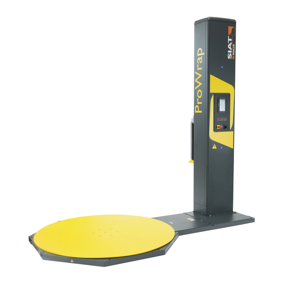
Page 17: Description Of The Main Components
Technical Specifications Description of the main components The image shows the main components and the list reports their description and function. A) Rotating platform: area on which are loaded the products to be wrapped. – The rotating platform is driven by a gear-motor with a chain drive. B) Column: it is used for vertical movement of reel holding carriage D. -
Page 18: Manufacturer And Machine Identification
Technical Specifications Manufacturer and machine identification The identification plate (pictured) is affixed directly to the machine. – In addition to the references for identification provided by the Manufacturer, they also list all the essential information for a safe operation. A) Manufacturer identification B) Space reserved for CE compli- ance marking C) Machine model... -
Page 19: Cycle
Technical Specifications Cycle The figure shows the operating cycle and indicates the main operating areas. Ê Stage – Correctly load the new product to be wrapped in the middle of rotating platform. – Tie the trailing end of the film to the base of the product to be wrapped. Ë... -
Page 20: Types Of Wrapping
Technical Specifications Types of wrapping The wrapping can be made in manual or automatic mode. – With the manual mode, platform rotates at a reduced speed, while reel holding carriage is activated by a non-release control. This mode allows for the wrapping to be made on an occasional basis, according to the specifications of the load to be wrapped (See “Control system.”). -
Page 21: Residual Risks
Technical Specifications Residual risks Residual risks are defined as: “Any risk that remains notwithstanding the safety solutions adopted and integrated during the design phase”. – Each residual risk is signalled with a special sign. Some of them are applied close to the areas where the risk is present, others are placed in an easily visible posi- tion. -
Page 22: Incorrect Uses That Are Reasonably Expected
Technical Specifications Incorrect uses that are reasonably expected Improper use: reasonably foreseeable use different from what is specified in the use manual, that may be caused by human behaviour. – ONLY trained, documented and authorized Operators are allowed to use the ma- chine. -
Page 23: Description Of The Safety Devices
Technical Specifications Description of the safety devices The machine is equipped with safety devices that reduce the risks during the man-machine interaction. A) Isolator switch: safety control to disconnect electric power supply. B) Emergency stop button: safety control that, in case of an imminent risk, stops all parts whose function might constitute a risk. -
Page 24: Technical Data Of Machine
Technical Specifications Technical data of machine Dimensions and weights (Standard version) ▀ ProWrap Weight of the Size of the load to be Diameter of the Dimensions of the Max weight of the load to be wrapped AxBxC (mm) platform (mm) machine LxWxH (mm) machine (kg) Model... -
Page 25: Dimensions And Weights (Version Hsd)
Technical Specifications Dimensions and weights (version HSD) ▀ ProWrap Max weight of Maximum size of the load to Diameter of the Dimensions of the Max weight of the the load to be be wrapped AxBxC (mm) platform (mm) machine LxWxH (mm) machine (kg) Model wrapped (kg) -
Page 26: Specifications Of The Accessories Available On Request
Technical Specifications Specifications of the accessories available on request ▀ Unit of Weight Capacity measurement Ramp 1000 Weighing unit 2000 Floating weighing unit 2000 Lifting frame 2000 Burying frame Technical data of reel Dimensions of film reel ▀ Unit of Value measurement Maximum external diameter D... -
Page 27: Description Of Outer Areas
Technical Specifications Description of outer areas The figure shows different areas to be considered in the planning of the instal- lation area. A) Operator control and stand- ing area B) Refill area for reel C) Loading/unloading area for the products to be wrapped D) Perimeter area Operation and maintenance manual English language... -
Page 28: Safety And Information Symbols
Technical Specifications Safety and information symbols The figure shows the applied signals and the list includes the description of the shown resid- ual risk. A) Electrical shock or electrocu- tion hazard: hazard signal that warns the operator from ac- cessing the areas under volt- age in order to avoid risks. -
Page 29: Maintenance
Maintenance Recommendations for maintenance interventions – The recommendations represent a summary of those shown in the SAFETY WARNINGS section. – The personnel authorized to carry out the ordinary maintenance must have qual- ified expertise and specific skills in the field of intervention. –... -
Page 30: Scheduled Maintenance Intervals
Maintenance Scheduled maintenance intervals Always keep the machine in optimum operating condition and carry out the routine maintenance according to the intervals and procedures specified by the Manufacturer. – In case of prolonged inactivity, carry out some maintenance operations in order to preserve functionality and prevent further damages. -
Page 31: Diagram Of The Points Of Lubrication
Maintenance Every 5000 work hours (max 12 months) Component Operation required Procedures to implement Vertical movement wheels of the reel - Check this component for wear. Checking holding carriage - Replace the component, if it is worn out - Check this component for wear. Rotation wheels of rotating platform Checking - Replace the component, if it is worn out... -
Page 32: Problems, Causes, Remedies
Maintenance Problems, causes, remedies The table shows the list of faults that can occur during the standard operation and it highlights possible remedies. Table: Operation failures Problem Cause Remedy - Identify the causes that have caused With isolator switch G on ON, pilot the stop. - Page 33 Maintenance Problem Cause Remedy - Remove any residues. Presence of residues or dust on the Use brushed with soft plastic bristles. reel holding carriage sliding guides The machine stops with the reel Press key D. holding carriage not correctly There is an obstacle under the reel - Remove the obstacle.
-
Page 34: Alarm Message Table
Maintenance Alarm message table Type of failure Remedy Machine alarms Sensor does not detect the rotation of - Check the connections and/or the position of sensor. platform. - Press control F to silence the alarm. (Lower and upper) sensors do not detect the - Check the connections and/or the position of sensors. - Page 35 Maintenance Type of failure Remedy Reel holder carriage inverter alarms The inverter parameters are not properly set - Contact the Manufacturer’s Technical Assistance Service. The activation of the inverter electric power is - Contact the Manufacturer’s Technical Assistance Service. not correctly enabled. The electric motor is damaged due to a short - Contact the Manufacturer’s Technical Assistance Service.
-
Page 36: Cleaning And Replacement Of The Air Filter
Maintenance Cleaning and replacement of the air filter The operation must be carried out by the maintenance technician or by per- sonnel with suitable competences, skills and knowledge. Make sure to fulfil the required requirements in order to work under safe con- ditions. -
Page 37: Adjustment Of Chain Controlling The Rotation Of Platform
Maintenance Adjustment of chain controlling the rotation of platform The operation must be carried out by the maintenance technician or by per- sonnel with suitable competences, skills and knowledge. Make sure to fulfil the required requirements in order to work under safe con- ditions. - Page 38 Maintenance 4° 10. Bring the column to a horizontal position. – Insert the shim E under the column to keep it horizontal. 5° 11. Slightly loosen the nuts F. 12. Adjust the tension of chain G by means of the adjusting system Important Do not overtighten so as not to cause any malfunctioning.
-
Page 39: Sensitivity Adjustment For The Product To Be Wrapped Detection Photocell
Maintenance Sensitivity adjustment for the product to be wrapped detection photocell The operation must be carried out by the maintenance technician or by per- sonnel with suitable competences, skills and knowledge. Make sure to fulfil the required requirements in order to work under safe con- ditions. -
Page 40: Replacing The Rotating Platform Wheels (Standard Version)
Maintenance Replacing the rotating platform wheels (standard version) The operation must be carried out by the maintenance technician or by per- sonnel with suitable competences, skills and knowledge. Make sure to fulfil the required requirements in order to work under safe con- ditions. -
Page 41: Replacing The Rotating Platform Wheels (Version Hsd)
Maintenance Replacing the rotating platform wheels (version HSD) The operation must be carried out by the maintenance technician or by per- sonnel with suitable competences, skills and knowledge. Make sure to fulfil the required requirements in order to work under safe con- ditions. - Page 42 Maintenance 11. Slightly lift the platform , re- move the supports and reposi- tion it on the base. – During repositioning, careful that the pin of the platform properly engages in bearing E. 12. Remove the lifting device. 13. Remove the eyebolts 14.
-
Page 43: Replacing The Lifting Belt Of The Carriage
Maintenance Replacing the lifting belt of the carriage The operation must be carried out by the maintenance technician or by per- sonnel with suitable competences, skills and knowledge. Make sure to fulfil the required requirements in order to work under safe con- ditions. - Page 44 Maintenance 5° 11. Remove the fastening ele- ments and remove the compo- nent K. 12. Disconnect all connectors from their sensors. 13. Slip out pin F. 6° 14. Partially remove the reel holder carriage to reach the fastening elements. 7° 15.
- Page 45 Maintenance 9° 22. Install the component K and lock it in place with the fasten- ing elements. 23. Connect the connectors to their sensors. 24. Keep the belt taut and move the reel holder carriage to match the base of the column. 10°...
-
Page 46: Pressing Roller
Pressing roller Description of the main components of the Pressing Roller The Pressing Roller keeps the product stabilised during wrapping. A) Pressing roller disc: it rests on the product to keep it stable. B) Pneumatic actuator: it is used to vertically move the pressing roller disc. -
Page 47: Disassembly And Re-Assembly Of The Pressing Roller
Pressing roller Disassembly and re-assembly of the Pressing Roller The operation must be carried out by the maintenance technician or by per- sonnel with suitable competences, skills and knowledge. Make sure to fulfil the required requirements in order to work under safe con- ditions. -
Page 48: Re-Assembly Of The Pressing Roller
Pressing roller Re-assembly ▀ Pressing Roller 1. Fit the component L and se- cure it with the screws H. 2. Introduce tighten screws G. 3. Re-install the front panel F and fasten it with the screws E. 4. Re-connect the electric and pneumatic connections. -
Page 49: Reel Holding Carriage (M)
Reel holding carriage (M) Reel holding carriage (M) Main components ▀ A) Structure: it is equipped with wheels for vertical shifting of carriage on column. – In the structure a fall arrest sys- tem is installed, which stops the carriage in case of lifting belt failure. -
Page 50: Film Coil Feeding
Reel holding carriage (M) Film Coil Feeding ▀ 1. Lower the reel holding carriage until its endstroke. 2. Lift the lever F to its vertical po- sition. 3. Remove the cardboard core of the reel. 4. Insert the new reel. Check whether the wrapping film same... -
Page 51: Tension Adjustment Of Film
Reel holding carriage (M) Tension adjustment of film ▀ – The operation is necessary to adjust the film tension on the load to be wrapped. 1. Lower the reel holding carriage until its endstroke. 2. Lift the lever F to its vertical po- sition. -
Page 52: Cleaning And Replacement Of Brake Disc
Reel holding carriage (M) Cleaning and replacement of brake disc ▀ – The operation must be carried out by the maintenance technician or by personnel with suitable competences, skills and knowledge. – Make sure to fulfil the required requirements in order to work under safe conditions. -
Page 53: Replacing The Outer Surface Of Roller
Reel holding carriage (M) Replacing the outer surface of roller ▀ – The operation must be carried out by the maintenance technician or by personnel with suitable competences, skills and knowledge. – Make sure to fulfil the required requirements in order to work under safe conditions. -
Page 54: Reel Holding Carriage (Fm)
Reel holding carriage (FM) Reel holding carriage (FM) Main components ▀ A) Structure: it is equipped with wheels for vertical shifting of carriage on column. – In the structure a fall arrest sys- tem is installed, which stops the carriage in case of lifting belt failure. -
Page 55: Film Coil Feeding
Reel holding carriage (FM) Film Coil Feeding ▀ 1. Lower the reel holding carriage until its endstroke. 2. Remove the cardboard core of the reel. 3. Insert the new reel. Check whether the wrapping film same chemi- cal-physical properties as that installed in the reel holder car- riage. -
Page 56: Cleaning And Replacement Of Brake Disc
Reel holding carriage (FM) Cleaning and replacement of brake disc ▀ – The operation must be carried out by the maintenance technician or by personnel with suitable competences, skills and knowledge. – Make sure to fulfil the required requirements in order to work under safe conditions. -
Page 57: Adjustment Of Brake
Reel holding carriage (FM) Adjustment of brake ▀ – The operation must be carried out by the maintenance technician or by personnel with suitable competences, skills and knowledge. – Make sure to fulfil the required requirements in order to work under safe conditions. -
Page 58: Replacing The Outer Surface Of Roller
Reel holding carriage (FM) Replacing the outer surface of roller ▀ – The operation must be carried out by the maintenance technician or by personnel with suitable competences, skills and knowledge. – Make sure to fulfil the required requirements in order to work under safe conditions. -
Page 59: Reel Holding Carriage (Pw)
Reel holding carriage (PW) Reel holding carriage (PW) Main components ▀ A) Structure: it is equipped with wheels for vertical shifting of carriage on column. – In the structure a fall arrest sys- tem is installed, which stops the carriage in case of lifting belt failure. -
Page 60: Film Coil Feeding
Reel holding carriage (PW) Film Coil Feeding ▀ 1. Lower the reel holding carriage until its endstroke. 2. Open the cover A. 3. Remove the cardboard core of the reel. 4. Insert the new reel. Check whether the wrapping film same chemi- cal-physical properties as that... -
Page 61: Adjustment Of Drive Chain Tensioning
Reel holding carriage (PW) Adjustment of drive chain tensioning ▀ – The operation must be carried out by the maintenance technician or by personnel with suitable competences, skills and knowledge. Make sure to fulfil the required requirements in order to work under safe conditions. -
Page 62: Pre-Stretch Percentage Variation (Film Pre-Stretch Kit )
Reel holding carriage (PW) Pre-stretch percentage variation (film pre-stretch kit ) ▀ – This service should be carried out with the reel holding carriage lowered and the machine safely at a stop. 1. Mark the intervention area and prevent access to the devices that, if activated, may cause unexpected hazards and jeop- ardize the safety level. - Page 63 Reel holding carriage (PW) 4° 8. Re-install the belt D on the pul- leys. 9. Manually adjust the tightener C to regulate the tension of belt D and,at the same time, tighten the screw B. Important Do not overtighten so as not to cause any malfunctioning.
-
Page 64: Disassembly And Re-Assembly Of The Reel Holding Carriage
Reel holding carriage (PW) Disassembly and re-assembly of the reel holding carriage ▀ – The operation must be carried out by the maintenance technician or by personnel with suitable competences, skills and knowledge. Make sure to fulfil the required requirements in order to work under safe conditions. -
Page 65: Control System
Control system Recommendations on Operation and Use – Consult the user manual, in particular during the first use, and make sure that you fully understand its content. – Find out the position and function of the controls and simulate some operations (in particular start and stop) in order to acquire familiarity. -
Page 66: Control Description
Control system Control description The illustration shows the main commands and their de- scription and function are listed. A) Operator interface: control system that programmes and displays the operating status of the labelling machine. – The operator interface has a touch-screen colour display with active matrix. -
Page 67: Description Of The Operator Interface
– “Advanced” level password: only for the personnel authorised to supervise the production activity. – Level “Siat” password: only for the Technical Assistance Service or the person- nel authorised by the manufacturer. The activities to be performed by operators do not require any password. -
Page 68: Operator Interface Navigation Diagram (Standard)
Control system Operator interface navigation diagram (standard) The figure shows the navigation logic diagram and the list includes the de- scription and the function of the screens. – Certain screens of the navigation logic diagram may develop in several displays. English language Operation and maintenance manual... - Page 69 Control system Name Function description - Screen appears after loading the software and shows the keys to access the MAIN screen other functions. - Screen displays the list of programmed recipes. RECIPES screen The controls in screen are enabled only during the operation in “automatic mode.”...
-
Page 70: Operator Interface Navigation Diagram (Advanced)
Control system Operator interface navigation diagram (advanced) The figure shows the navigation logic diagram and the list includes the de- scription and the function of the screens. – Certain screens of the navigation logic diagram may develop in several displays. English language Operation and maintenance manual... - Page 71 Control system Name Function description - Screen appears after loading the software and shows the keys to access the MAIN screen other functions. - Screen displays the parameters that are intended only for the personnel ADVANCED DASHBOARD authorised to supervise the production activity and to create or modify the screen recipes.
-
Page 72: Description Of A Typical Screen
Control system Description of a typical screen The figure shows an example of a “typical screen” and the areas in common with other screens are highlighted; the list includes the description of the rel- evant functions. – Carefully read the functions of the elements in common with all the screens in order to “navigate”... -
Page 73: Function Description Of The Displayed Icons
Control system Function description of the displayed icons The figures show the displayed icons and the list includes the relevant func- tion. Programming icons (shaded gray background) ▀ – It programmes the thickness of the film (only for reel holding car- riage of type PW - DM). - Page 74 Control system – It programmes the lifting level of the reel holding carriage , beyond the edge of the load to be wrapped. If you touch the image , the control will be displayed to programme the lifting time. – It programmes the lifting time of the reel holding carriage beyond the edge of the load to be wrapped.
-
Page 75: Display Icons (Gray Background)
Control system – It programmes the rotating speed of platform during the lowering of the reel holding carriage (Only with enabled double automatic wrapping). The value is expressed as a percentage compared with the pro- grammed operating speed. – It programmes the angular position of the rotating platform at the end of the lifting of the reel holding carriage. -
Page 76: Non-Release Hold Keys (Shaded Gray Background)
Control system – Instant speed (lifting and lowering) of the reel holding carriage The value is expressed as a percentage compared with the pro- grammed operating speed. – Instant rotation speed of the platform The value is expressed as a percentage compared with the pro- grammed operating speed. - Page 77 Control system – It enables the single automatic wrapping (lifting of the reel holding carriage) – It enables the double automatic wrapping (lifting and lowering of the reel holding carriage) – It enables and disables the working cycle with sheet feeder –...
-
Page 78: Language Selection Mode
Control system Language selection mode The figure shows the points of intervention and the description shows the procedures to be adopted. 1. Display the LANGUAGES screen (6) (See “Operator inter- face navigation diagram (standard)”). 2. Touch the icon that corresponds to the desired language. –... -
Page 79: How To Programme Or Edit The Parameters
Control system How to programme or edit the parameters The figure shows the points of intervention and the description shows the procedures to be adopted. 1. Stop the machine 2. Display the desired screens (one at a time) where you need to programme or edit the values. -
Page 80: Modifying A Recipe
Control system Modifying a recipe ▀ 1. Display the ADVANCED SETTINGS screen (8) (See “Operator interface navigation diagram (standard)”). 2. Press key E. – The display shows the PARAMETER screen (9). 3. Touch the area F. 4. Select the desired recipe from the drop-down menu. -
Page 81: How To Load A Recipe In The Plc
Control system How to load a recipe in the PLC ▀ 1. Display the MAIN screen (1) (See “Operator in- terface navigation diagram (standard)”). 2. Press key K. 3. Touch the area A. – The display shows the RECIPES screen (2). 4. -
Page 82: How To Programme The Bands And The Wrapping Reinforcements
Control system How to programme the bands and the wrapping reinforcements The figure shows the screens to programme the wrapping and the reinforce- ments. You can programme up to 6 different reinforcement and wrapping areas. English language Operation and maintenance manual... - Page 83 Control system Name Function description PARAMETERS screen - Press the key to display the WRAPPING screen (9.1). - The screen displays the controls that are used to access the reference functions. The summary shows (in different colours) the quantity and the type of the 9.1 WRAPPING screen programmed wrapping and reinforcement bands.
- Page 84 Control system English language Operation and maintenance manual...
- Page 85 Control system Name Function description - The screen displays the fields that are used to programme the wrapping parameters. - Column A: ID of the wrapping area. - Column B: height of the corresponding wrapping area. - Column C: rotating speed of the platform within the corresponding wrapping area (The value is expressed as a percentage compared with the programmed operating speed).
-
Page 86: How To Display The Wrapping Statistics
Control system How to display the wrapping statistics The figure shows the screens with wrapping statistical data. English language Operation and maintenance manual... - Page 87 Control system Name Function description ADVANCED DASHBOARD - Press the key to display the COUNTERS screen (11). screen - The screen displays the controls that are used to access the reference functions. The areas show some machine operation statistics. COUNTERS screen - Machine (partial and total) operating hours.
-
Page 88: How To Display The Setup Parameters
Control system How to display the Setup parameters The figure shows the screens to programme the operation of the machine. English language Operation and maintenance manual... - Page 89 Control system The functions in the screens (12.1 - 12.2 - 12.3 - 12.4) are not described be- cause they are intended for the Customer Assistance Service of the Manufac- turer. Name Function description ADVANCED DASHBOARD Press the key to display the TOOLS screen (12). screen TOOLS screen - Screen displays the controls that are used to access the relevant functions.
-
Page 90: Manual Wrapping
Control system Manual wrapping The figure shows the points of intervention and the description shows the procedures to be adopted. 1. Check whether the wrapping film has the same chemi- cal-physical properties as that installed in the reel holder carriage. –... -
Page 91: Normal Stop
Control system – Press and hold button L to move reel holder carriage to the low position. Upper reinforcing band with reel holder carriage descent (dou- ▀ ble wrapping) – Release button H when the reel holder carriage reaches the upper part of the product. -
Page 92: (Single Or Double) Automatic Wrapping
Control system (Single or double) automatic wrapping The figure shows the points of intervention and the description shows the procedures to be adopted. 1. Check whether the wrapping film has the same chemi- cal-physical properties as that installed in the reel holder carriage. -
Page 93: Normal Stop
Control system – Double mode: the wrapping stops automatically with the reel holder carriage at the starting point (lower side of the load). 10. Manually cut the film and cause it to adhere to the wrapped product. Important Keep the reel suitably refilled to prevent to avoid interrupting the wrapping due to absence of film. -
Page 94: (Single Or Double) Automatic Wrapping With Sheet Feeder
Control system (Single or double) automatic wrapping with sheet feeder The figure shows the points of intervention and the description shows the procedures to be adopted. 1. Check whether the wrapping film has the same chemi- cal-physical properties as that installed in the reel holder carriage. -
Page 95: Normal Stop
Control system Press button D to move reel holder carriage to the start of the cycle (lower part). – Double mode: the wrapping stops automatically with the reel holder carriage at the upper side of the load. – Insert the covering sheet. –... -
Page 96: Stop In Alarm Conditions And Restart
Control system Stop in alarm conditions and restart The figure shows the points of intervention and the description shows the procedures to be adopted. – All moving devices will automatically stop in case of alarm conditions any time there is an irregular operation. –... -
Page 97: Emergency Stop And New Start-Up
Control system Emergency stop and new start-up The figure shows the points of intervention and the description shows the procedures to be adopted. 1. In the presence of an imminent risk press emergency button – All moving devices immediately stop. –... -
Page 98: Use Of The Weighing Unit (Optional)
Control system Use of the weighing unit (optional) Weighing shall be carried out ONLY with the system stopped, before starting or after completing the wrapping. The measured value is not valid for fiscal use. – The figure shows the points of intervention and the description shows the proce- dures to be adopted. -
Page 99: Calculation Of Film Pre-Stretch
Control system Calculation of film pre-stretch The procedure is used to check if the programmed film pre-stretch corre- sponds to the real value. – The figure shows the points of intervention and the description shows the proce- dures to be adopted. 1. -
Page 100: Calculation Of Film Tensioning
Control system 17. Apply the formula to find the film pre-stretch value. Specific weight of the film (g/m) - Weight per meter of the used film (g/m) = Pre-stretch Weight per meter of the used film (g/m) 18. Check that the film pre-stretch corresponds to the set value. Important If the values do not match, call the manufacturer’s Technical Assistance Ser- vice. -
Page 101: 1Disposal And Scrapping
Disposal and scrapping Machine Disposal and Scrapping Machine dismantling ▀ – Disconnect the supplies form the energy sources (electrical, pneumatic, etc.) in order to prevent any restart. – Carefully drain the systems containing hazardous substances, according to the applicable regulations on safety at work and environmental protection. –... - Page 102 Disposal and scrapping English language Operation and maintenance manual...
-
Page 103: Analytical Index
Analytical index – Manufacturer and machine identification, 16 – Adjustment of chain controlling the rotation of platform, – Operator interface navigation diagram (advanced), 68 – Alarm message table, 32 – Operator interface navigation diagram (standard), 66 – Attached documentation, 4 –... - Page 104 – Sensitivity adjustment for the product to be wrapped detection photocell, 37 – (Single or double) automatic wrapping, 90 - Normal stop, 91 – (Single or double) automatic wrapping with sheet feeder, 92 - Normal stop, 93 – Stop in alarm conditions and restart, 94 –...
Need help?
Do you have a question about the ProWrap Series and is the answer not in the manual?
Questions and answers