Table of Contents
Advertisement
Advertisement
Table of Contents

Summary of Contents for Ningbo Benye 40 Series
-
Page 2: Table Of Contents
Contents Preface……………………………………………………………………….. Chapter Ⅰ . Main Technical Specifications of the Tractor………………….. I Specifications of the Tractor ……………………………………………………... Ⅱ Engine ……………………………………………………………………………. Ⅲ Transmission System …………………………………………………………….. Ⅳ Wheels and Steering System……………………………………………………... Ⅴ Braking System ………………………………………………………………….. Ⅵ Hydraulic Lifting and PTO………………………………………………………. Ⅶ Electrical Equipment and Instruments …………………………………………... Ⅷ... - Page 3 A. Starting of the Engine…………………………………………………………... B. Driving of the Tractor…………………………………………………………... C. Steering of the Tractor………………………………………………………….. D. Gear Shifting of the Tractor……………………………………………………. E. Braking of the Tractor…………………………………………………………... F. Operation of Front Drive………………………………………………………... G. Operation of Differential Lock…………………………………………………. H. Stopping of Tractor and Shutting off of Engine………………………………... Ⅲ...
- Page 4 Ⅳ Transfer Case………………………………………………………………………. Ⅴ Brake………………………………………………………………………………. Ⅵ Steering Gear………………………………………………………………………. Ⅶ Front Axle…………………………………………………………………………. ⅧWheel ……………………………………………………………………………... Ⅸ Hydraulic Hitch Linkages…………………………………………………………. Ⅹ Electrical Equipment………………………………………………………………. Chapter Ⅶ Main Troubles and Their Disposals of the Tractor…………….. AppendixⅠ ………………………………………………………………….. Ⅰ Oil Seal Detailed Table of the Tractor –BY350(400)……………………………... Ⅱ...
- Page 5 Appendix Ⅲ ……………………………………………………………….. Ⅰ Sketch of Transmission System ………………………………………………………. Ⅱ Diagram of Linkage Hitch …………………………………………………………….. ·4·...
-
Page 6: Preface
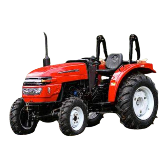
Preface Model BENYE 35-40 Series Tractor is of medium-size wheeled agricultural tractor, suitable for both paddy and dry fields. The tractor is featured by reasonable structure, easy operation, sensitive steering, easy maintenance and so on. Equipped with different farm implements, it can perform ploughing, harrowing, sowing, harvesting and transporting. -
Page 7: Chapter Ⅰ . Main Technical Specifications Of The Tractor
Chapter Ⅰ Main Technical Specifications of the Tractor Ⅰ . Specifications of the Tractor Model BY350 BY354 BY400 BY404 Dry & Paddy Dry & Paddy Dry & Paddy Dry & Paddy Fields, Fields, Fields, Fields, Type Two-wheel Four-wheel Two-wheel Four-wheel Drive Drive Drive... -
Page 8: Ⅱ Engine
Ⅴ 8.68 8.00 9.06 8.35 Ⅵ 10.96 10.10 11.44 10.54 Ⅶ 17.85 16.44 18.62 17.16 Ⅷ 28.30 28.08 29.53 27.21 ReverseⅠ 1.90 1.75 1.99 1.83 Reverse Ⅱ 8.10 7.46 8.45 7.79 Ⅱ Engine Model of Tractor BY350 BY354 BY400 BY404 Model TY395IT (Jiangdong) 490T(Xinchang) -
Page 9: Ⅴ Braking System
Planetary gear Planetary gear Front Axle final drive final drive Front Tire 2×5.50-16 2×7.50-16 2×5.50-16 2×7.50-16 Rear Tire (ordinary 2×11.2-28 type) Tires Rear Tire (high lug rubber type 2×11-28 paddy field) Front Wheel 220-250 190-210 220-250 190-210 Tire Rear Wheel Inflation 80-110 (ordinary type) -
Page 10: Ⅶ Electrical Equipment And Instruments
At the point of 610mm frame point ≥ 5.79 Max. Lifting Capacity (kN) Position Rear location on right side M16×1.5 inside diameter ≥ф8 Hydraulic Inside Specification Output Output Hole Numbers Joint Pressure Theoretical Flow Rate of Oil Pump 20.65(2300r/min),24(2400r/min) PTO shaft Type Dependent Standard Speed (r/min) (with 80%-90% of the rated... - Page 11 Front Head Lamp ND140×90T-1,2 Rear Lamp WD140×90T-1 Lighter Signaling Front Light H107,2 Device Rear Light XH8-5,NJ130,2(for export) Horn DL1290 307C 30A/12V Ammeter Controlling 302A(CA10)40-100 Water Temperature and Alarming C/12V Device 308A(CA10)0-0.5Mp Oil Pressure Gauge ZB114A ZB114A a/12V Hour Meter D-704-1F(for export) ⅧMain Filling Capacities.
-
Page 12: Chapter Ⅱ . Safety Regulations And Notices In Operation
Chapter II. Safety Regulations and Important Notices in Operation of the Tractor Ⅰ . Safety Regulations. A. The tractor can be operated only by the especially trained operator. B. Before starting-up, it is necessary to see whether there is any obstacle on road, or any person between the tractor and farm implement or trailer. - Page 13 other heavy implement, four-wheel-drive tractors are recommended.. The tractor can be attached with a four-wheel-trailer less than 4 tons. Remove weeds and dust on radiator in time to ensure normal radiation. When a radiator is overheated, cold water is forbidden to be poured into the engine or the radiator to avoid of damaging the block.
-
Page 14: Chapter Ⅲ . Running-In Of The Tractor
Chapter III. Running-in of the Tractor A new or overhauled tractor can be only used after the running-in. Otherwise, the service life shall be shortened. I. Preparatory Work Before Running-in. Clean up the appearance of the tractor. Check and tighten the outer nuts and bolts. Fill lubricating oil, fuel and water to the specific levels. -
Page 15: Ⅲ Works After The Running-In
low gear to the higher. List of loaded running-in and the loads Ⅲ Ⅳ Ⅴ Ⅵ Load(N) Gear Total Approximate Towing Force 4-wheel trailer attached, load 2500 kgs, 2000 transportation on road. 3-share plough draft, tillage width 68 cm, 4000 Time(h) depth 14 cm. -
Page 16: Chapter Ⅳ. Operation Of The Tractor
Chapter IV. Operation of the Tractor I. Control Mechanism, Instruments and Switches A. Preheating Switch When inserted into the switch at position "O", circuits are disconnected, and when it is turned clockwise to the position "D", all circuits expect the starting and pre-heating circuits,... - Page 17 position, power is cut off. clutch pedal must be pressed down before its engagement. G. Draft Position Adjusting Levers Push either the draft lever or the position lever forward to lower the implement. But in lifting, the both levers must be put in the lifting position (the final end).
-
Page 18: Ⅱ Control And Operation Of The Tractor
II. Operation and Driving the Tractor A. Start of the Engine. a. Preparatory work (1).Check with oil dipstick the lubricating oil level of engine sump and gearbox, which necessarily remains between the upper and lower scale lines (Fig.4-4 and 4-5). For the four -wheel- drive tractor, it is necessary to check with oil dipstick the oil level of the front axle (front axle in level position), which exists within 5 mm above or below the dipstick scale line. -
Page 19: Driving Of The Tractor
(4). Push the shut -off lever to the fuel -supplying position. (5). Hand throttle in semi-open state (medium fuel supply position). (6).Put the control levers of gearbox PTO shaft and front-drive handle in neutral position. (7). Insert the key into the preheating switch. (8) If restart a tractor being cold or being stored for a long time, loosen the air-releasing screw in injection pump, press with hand the Handle-2 of the pump, and tighten the air releasing screw after the air is released. -
Page 20: Steering Of The Tractor
C. Steering of the tractor a. Tractor steering is actuated by steering the wheel. A sharp-turn is allowed only at lower running speeds. On farm working (especially in paddy field ),one-side-braking can be used to promote productivity and maneuverability by reducing turning radius. While working at higher speeds or in transportation, it is forbidden to make a sharp-turn with one-side-braking to avoid of turning-over of the tractor. -
Page 21: Braking Of The Tractor
c. Notices in driving. 1. The readings of the gauges should always be noticed. The readings of oil gauge should be within 196--343 Kpa (2--3.5 Kg/cm ); that of the water thermometer within 70--90 C; that of the ammeter in middle position, or "+" direction of charging. If any of the gauges is out of order, it should be repaired or changed, and never be remained in service. -
Page 22: Operation Of Differential Lock
down for complete separation, and then the control handle should be lifted up or pressed down before the power is supplied or cut off. G.Use of Differential Lock. When one side of the rear wheels of the tractor slips and sanks, the differential lock handle should be pushed to the right , and the two semi-shaft gears and the block of the differential are rigidly locked together to make rear wheels moving at the same time... -
Page 23: Ⅲ Control And Operation Of Working Devices
Ⅲ . Control and Operation of Working Devices Control and Operation of Hydraulic Hitch. The hydraulic hitch system is used to lift the implement when the tractor is driven to another place, to adjust the tillage depth of the implement in tillage ,and to supply pressure oil to another equipped machines (such as automatic unloading tractor) . -
Page 24: Control And Operation Of Hydraulic Hitch
adjusted before leaving the manufacturer. It is unnecessary to change them. Working on farm, the implement should be lifted up before the tractor turns, and lowered only after it has turned and is running in straight line. The draft control handle does not permit to lower the implement on hard ground, which could destroy the handle due to high speed lowering. -
Page 25: Control And Operation Of Pto Shaft
position No.2 of the joint point in the rock arm. In case of great earth resistance, the front end of the upper link connects to the position No.3 of the joint pin in the rocker arm to ensure the tillage depth. - Page 26 b. Take off the sealing cover and its paper gasket from the oil pump and fasten them. c. Fix the pulley assy. on the PTO shaft. d. Push the auxiliary gearshift lever to the neutral position, the main lever in the positions of Gear I and II (to have the bearing of the I-shaft completely lubricated), the output drive shaft handle in the engaged position, the PTO shaft handle in low speed positions, and then keep the pulley running at low speeds.
-
Page 27: Chapter Ⅴ . Technical Maintenance Of The Tractor
Chapter V. Technical Maintenance of the Tractor In order to keep the tractor in normal working condition and prolong its service life, the technical maintenance should be strictly carried out. Based on the working hours, the technical maintenance regulations are classified as follows. A. -
Page 28: Ⅲ Technical Maintenance After 500H Accumulated Working Hours
E. Screw off the screw plug of fuel tank to release the fuel and wash it. F. Brush the air cleaner. G. Clean the outlook of battery, inspect the specific gravity of electrolyte of battery (1.285). If necessary, recharge it additionally. Clean away rust on battery poles, and coat them with grease against corrosion. -
Page 29: Ⅴ Special Maintenance In Winter
D. Change the diesel, oil and air filter elements. E. Check and adjust the gear pair bearing clearance in the central transmission. F. Replace the grease in the bearings of the front hub. G. Check the sleeve of each gear, the seal ring and the frame oil seal , replace them if necessary. H.Check the oil level in the steering gear case. -
Page 30: Chapter Ⅵ. Main Components Adjustment Of The Tractor
Chapter VI. Main Components Adjustment of the Tractor. This chapter mainly introduces checking and adjusting the main components of the chassis. The checking and adjusting of the diesel engine should be carried out as stipulated in Diesel Engine Operator's Manual. I. - Page 31 B. Maintenance of clutch a. The screw plug at the bottom of the flywheel should be often turned out to check whether there is any water or oil leaked in to avoid of clutch disk slipping due to the oil or water. In the case of any oil or water leaked in, the oil seals at the rear of the engine crank shaft and the...
- Page 32 with two semi-shaft gears. The differential component lock (11) is set on the differential housing. b. Adjustment Differential Assy. Put the differential assy into the middle of the differential housing (the big bevel gear put on the right side), set the internal circles of the bearing 7212 E and the adjusting nuts if the differential on the two shaft neck ends...
- Page 33 bevel gear of the II-shaft should be kept within the range of 0.98--1.47 N.m.(0.1--0.15 Kg.fm). IV. Transfer Case. The transfer case of BY354 and 404 four-wheel-drive tractors, is fixed below the carrier case, consists of a gear shaft connecting shaft , PTI and PTO shafts, gears, a transmission shaft, etc., and is used to take out or cut off the power from the front drive axle and to keep the front and rear drive wheels synchronously rotating.
- Page 34 The brake has been adjusted before leaving the manufacturer. The left and right pedals can be easily linked together or separated. In the case of locking together, the left and right drive wheels can be braked simultaneously when the pedals are stepped down. Wearing of the brake friction disk can cause the free travel longer and unindentical brake of the two wheels.
- Page 35 travel exceeds 30 When adjusting, loosen the nut (5) on the right side if steering gear case, turn clockwise the adjusting screw (4) and decrease the backlash of the mesh until when the steering pitman is on the middle position and the steering wheel can be turned to the left and right within 45 , there would be no backlash between gear rack and gear sector.
- Page 36 VII. Front Axle. Ⅰ . The front axle of BY--350 and 400 tractors is of U pipe and adjustable wheel base, which connects the front part of engine with pendulum shaft through the front bracket. Equipped with front wheels, it bears the weight of the front part of the tractor A.
- Page 37 ensure the necessary clearance. II. BY--354 /404 Four -Wheel-Drive Tractor The power of the front-drive is transmitted into the front central transmission by the roll shaft coupler of the transfer case under the bridge body, and then is provided to the both sides of the semi-shaft.
- Page 38 performed without adjusting their clearance. The structure is as indicated in Fig.6--13. E. Maintenance of Front Axle a. According to the stipulated technical maintenance in the operator's manual, unscrew the bolt (6) on the top of the semi-shaft housing (Fig.6--11),and check the oil level in the front axle.
- Page 39 ground to prevent the tires from being pressed. Do not release the air off. Hydraulic Hitch Linkage The hydraulic hitch linkage is combined by a lift, a gear pump, a pipe assy., and a hitch linkage. A. The fixing place of the lift arm on the lifting shaft.
- Page 40 forms 60 with the level plane. When a heel of 8 mm thick is inserted between the internal lift arm and the lift housing for convenient adjustment, the current lift arm position is considered as reaching the place required. Loosen the tightening bolt on the position control cam (29), turn the position control cam to extend the main control valve 17 mm from the distributor housing, and tighten the bolt on the cam.
- Page 41 ·40·...
- Page 42 A . Power Resource The power resource consists of a battery, a generator and a controller. The ammeter inspects the working state, and two 30 A fuse links protect respectively the charging and the releasing circulates. Analysis of power resource working state when engine running at high speed. a.: pointer of ammeter pointing to "0".
- Page 43 rotating timer, steering indicating lights, a charging-alarm indicating device, etc. ·42·...
- Page 44 Chapter VII. Main Troubles and Their Disposal (If there is any trouble in the engine, you are suggested to refer to The Engine Manual. ) Clutch Symptoms Possible Causes Remedies a. friction disk contaminated clutch slipping. with oil. a. wash with gasoline and eliminate the (with heavy load, the sound b.
- Page 45 over tight fitting between slide gear and spline shaft a. lubricating oil not enough. b. bearing or gear severely a. add to the stipulated level. abnormal sound from worn. b. replace the gear or bearing. transfer case of gear box . c.
- Page 46 returning automatically to the shaft and spool. b. adjust the play. middle position, b. no axial play between c. replay the piston sealing ring. steering shaft and spool.. c. return spring broken. a. axial and radial play of stator and rotor. b.
- Page 47 e. repair or replace. a. no oil pressure in the system. severely short of oil in lift housing; connector seal ring of oil pipe damaged, or poor a. add up oil to the stipulated level. self-tightening oil seal of hydraulic oil b.
- Page 48 Unable engaged a. starter drive gear and flywheel gear being worn. between starter drive gear b. early closure of switch resulting in starter to run before engagement of and flywheel gear, and with starter drive gear and flywheel gear. impacting noise. ·47·...
- Page 49 Appendices. I I . Detailed List of oil Seal BY350 (400) Qty./ Drawing No. Part Name Main Dimension Place Fixed Pressing cover, drive JB2600-80 Frame Rubber Oil Seal PD80x105x12 shaft, JB2600-80 Frame Rubber Oil Seal PD65x105x12 Drive shaft. JB2600-80 Frame Rubber Oil Seal PD55x105x12 Pulley JB2600-80...
- Page 50 Single-row, radial ball 40x90x23 End Transmission GB276--89 bearing. Ball bearing with stop 50307 35x80x21 Transmission Case GB277--89 groove Ball bearing with stop 50309 45x100x25 End Transmission GB277-89 groove Single-row, radial ball 60203 17x40x12 Flywheel GB278-82 bearing with dust cup. Single-row radial small 92608 cylindrical roller...
- Page 51 Ⅲ . Fitting Clearance of Main Parts in Tractor Frame. (Unit: mm) Standard Dimension Using Name Fitted Type Required Limit Components Hole Shaft Fitting Range Release bearing & its Φ53 Φ53 Transition seat. Height tolerance same 0.15 three release levers height Φ35+0.039 Φ35-0.025...
- Page 52 Φ10+0.033 Φ10+0.006 Oil return valve & its Clearance 0.006--0.012 sleeve -0.009 selected Φ22+0.033 Φ22+0.015 Distribution housing & Transition -0.001--0.018 oil return valve sleeve -0.018 selected IV. Attachment (Selected additionally by users.) .No. Part Code. No. Component Qty. Remarks. Against sunlight, 350.45.001 Driver' s roof assy.
- Page 53 Dia .x Width Low pressure pipe of gear pump, CB5-75 26x20.2x2 copper release oil pipe of lift. High pressure oil pipe of gear pump, CB5-75 23x17.2x2 copper head of oil intake component. Screw plug of oil release pipe, screw CB5-75 22.5x16.5x2 plug of output hole, oil cylinder copper...
- Page 54 Adjusting lever of shut-off valve. Oil inlet pipe of lift and distributor housing. Safety valve assy. GB1255-76 16x2.4 Connecting surface of distributor and oil cylinder. Universal drive shaft of speed-control valve and lift housing. Plug of distributor. Outlet oil pipe, lift. GB1235-76 13x1.9 Connecting surface of upper cover and distributor.
- Page 55 Select different lubricatings according to different weather conditions. The details are as per Chapter I: Lubricating Oil of the Tractor. ·54·...
- Page 56 Appendix II. I. Detailed List of Bearing. Main Qty/ Type Part Name Place Fixed Code Dimension Single-row radial 30x62x16 PTO shaft of transfer case GB276-82 ball bearing Single-row radial 45x85x19 Front drive bevel gear(1) GB276-82 ball bearing Single-row radial 20x52x15 PTI shaft of transfer case.
- Page 57 13/32" II. Detailed List of O-type Ring.---BY354(404) External (inner) Dia. Code No. Place Fixed Surface Dia. GB1235-76 16X2.4 Front central transmission screw plug GB1235-76 16X2.4 (left and right) Final transmission screw plug. GB1235-76 16X2.4 Oil release plug of transfer case. GB1235-76 20X2.4 Fork assy.
- Page 58 φ84H8( 0 φ84f6(-0.058) and shaft seat Sleeve and main +0.039 -0.050 clearance 0.050-0.080 φ45H8( 0 φ45e6(-0.066) pin shaft end φ35FB(+0.064) φ35h8(0 Sleeve and clearance 0.025--0.06 semi-shaft gear. (+0.025) (-0.039) PTO gear and +0.052 -0.020 PTO shaft of clearance 0.030--0.06 φ28H9(0 φ28f7(-0.041) transfer case Ⅴ...
- Page 59 Appendix Ⅲ ·58·...
- Page 60 II. Dimensional Sketch of linkage System. ---------END----------- ·59·...
- Page 61 ·60·...
Need help?
Do you have a question about the Benye 40 Series and is the answer not in the manual?
Questions and answers