Advertisement
Installer's Guide
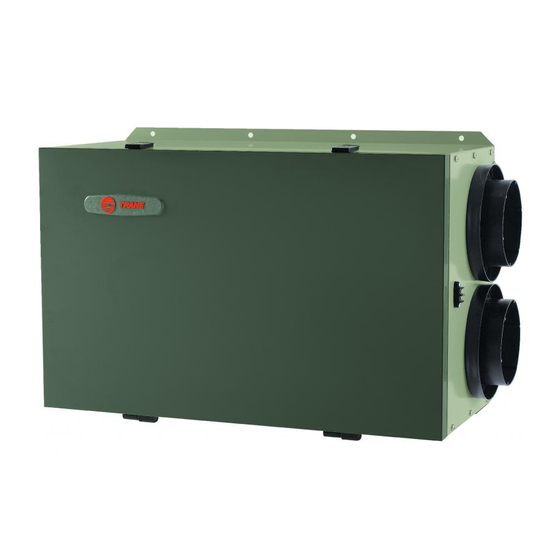
Energy Recovery Ventilator (ERV)
*ERVR100A9P00A
*ERVR200A9P00A
*ERVR300A9P00A
*First letter may be "A" or "T"
WARNING:
ALL phases of this installation must comply with NATIONAL, STATE AND LOCAL CODES
IMPORTANT — This Document is customer property and is to remain with this unit. Please return to service information pack
upon completion of work.
A. GENERAL INFORMATION
WARNING
!
THIS INFORMATION IS FOR USE BY INDIVIDUALS
HAVING ADEQUATE BACKGROUNDS OF ELECTRICAL
AND MECHANICAL EXPERIENCE. ANY ATTEMPT TO
REPAIR A CENTRAL AIR CONDITIONING PRODUCT
INCLUDING AN ERV MAY RESULT IN PERSONAL IN-
JURY AND/OR PROPERTY DAMAGE. THE MANUFAC-
TURER OR SELLER CANNOT BE RESPONSIBLE FOR
THE INTERPRETATION OF THIS INFORMATION, NOR
CAN IT ASSUME ANY LIABILITY IN CONNECTION WITH
ITS USE.
CAUTION
!
To prevent shortening its service life, the ERV should not
be used during the finishing phases of construction.
Compounds used in construction and construction dust
may cause rapid deterioration of the cabinet and internal
components. To avoid damage keep drywall spray,
construction dust, etc from entering the air stream of the
unit.
These instructions do not cover all variations in systems or
provide for every possible contingency. Should further
information be desired or particular problems arise which are
not covered sufficiently by this manual, contact your local
distributor or the manufacturer as listed on the ERV name-
plate.
BEFORE YOU BEGIN THE INSTALLATION
Check carefully for any shipping damage. This must be
reported to and claims made against the transportation
company immediately. Open carton, remove packing
material, loose parts and ship-with literature. Check to be
sure all major components are in the unit. Any missing
parts should be reported to your supplier at once, and
replaced with authorized parts only.
HAZARDOUS VOLTAGE - DISCONNECT POWER BEFORE SERVICING
Contents
General Information
Installation Limitations & Recommendations
Unit Installation
Installation on a concrete wall
Installation on a stud wall
Installation on floor joists
Installation on roof rafters
Duct Connections
Electrical Controls
Percent Timer Control
Push Button Point-of-use Control
Checkout Procedure
Figure 1
18-HE58D1-3
1
1-2
2-5
2-3
3
3
3-4
6-7
7
8
8-9
10
Advertisement
Table of Contents

Subscribe to Our Youtube Channel
Related Manuals for American Standard AERVR100A9P00A

Summary of Contents for American Standard AERVR100A9P00A
- Page 1 Installer’s Guide 18-HE58D1-3 Energy Recovery Ventilator (ERV) *ERVR100A9P00A *ERVR200A9P00A *ERVR300A9P00A *First letter may be "A" or "T" WARNING: HAZARDOUS VOLTAGE - DISCONNECT POWER BEFORE SERVICING ALL phases of this installation must comply with NATIONAL, STATE AND LOCAL CODES IMPORTANT — This Document is customer property and is to remain with this unit. Please return to service information pack upon completion of work.
-
Page 2: Unit Installation
This installation manual shows the suggested installa- tion method. Any structural alterations necessary for installation must comply with all applicable building, health and safety code requirements. 18-HE58D1-3 © 2006 American Standard Inc. All Rights Reserved... -
Page 3: He58D1
Installer’s Guide ATTIC INSTALLATION INSTALLATION ON ROOF RAFTERS Foam Tape The unit may be mounted directly to the roof rafters. (See Metal Washer Figure 3) Mount as described for installation on a con- crete foundation wall except use appropriate fasteners for Lag Screw or Co nc rete a roof rafter. - Page 4 Figure 6c - Hinges on Top NOT AN APPROVED MOUNTING POSITION HINGE HINGE Figure 6d - Hinges on Left Do not install in this position, as door will fall off when opened 18-HE58D1-3 © 2006 American Standard Inc. All Rights Reserved...
- Page 5 Installer’s Guide II)Separate Return Air and Fresh Air Supply INSTALLATION GUIDELINES Living area* GENERAL GUIDELINES 1) Do operate the ERV independent of the indoor central heating and cooling blower system (furnace / air handler). Independent operation of the ERV allows Furnace RA (Furnace) the ERV to introduce the minimum required fresh air...
- Page 6 Installer’s Guide IV) EXHAUST AIR FROM RETURN DUCT / FRESH AIR DUCTWORK INSTALLATION - ERV TO EXTE- DUCTED TO SUPPLY AIR DUCT RIOR WALL OUTLETS CAUTION Install internal elbow here Failure to follow this installation instruction may result in property damage from sweating ductwork. Minimum 3' The fresh air duct and exhaust air duct connect the ERV to the exterior wall outlet.
-
Page 7: Duct Connections
Installer’s Guide 12 in. min above snow line 10 Ft. min Fill and seal COMPLETELY Legend RA - Room Air with Expanded Foam OA - Outside Air FA - Fresh Air EA - Exhaust Air Figure 13 DUCTWORK CONNECTING ERV TO INDOOR Figure 12 TERMINATION POINTS The exhaust outlet and fresh air inlet on the outside of the... -
Page 8: Electrical Controls
Installer’s Guide insulated flexible duct from the ERV port labeled “Fresh ventilation airflow requirement per local code or calculate Air To Inside” to the point of termination. the minimum airflow required per ASHRAE 62.2-2004. During winter, since fresh air is unconditioned, the fresh In addition to the PT control some installations may air supply grilles should be located in a traffic area like a include Push Button (PB) or point of use control(s). -
Page 9: Push Button Point-Of-Use Control
Installer’s Guide NOTE for ERV systems with more than one INSTALLATION control: Install control in a standard 2" x 4" electrical box, Another control may be causing your ventilator to run - with a minimum depth of 1.5", with the two screws even if the runtime % light on this control is off. -
Page 10: Checkout Procedure
Installer’s Guide START-UP AND CHECK OUT PROCEDURE Make sure power is disconnect by unplugging electri- cal cord. Check field-supplied control wiring to insure proper installation and that all connection are tight. Check field-supplied power supply for proper voltage Make sure that unit is securely mounted or sus- pended and that there are no tools or loose debris in, around or on top of the unit Check all duct connection to insure they are sealed... - Page 11 Installer’s Guide 18-HE58D1-3...
- Page 12 American Standard Inc. 10/05 6200 Troup Highway Tyler, TX 75711 Since the manufacturer has a policy of continuous product and product data improvement, it reserves the right to For more information contact your local dealer (distributor) change design and specifications without notice.
Need help?
Do you have a question about the AERVR100A9P00A and is the answer not in the manual?
Questions and answers