
Subscribe to Our Youtube Channel
Related Manuals for Raymarine SEATALK NG

Summary of Contents for Raymarine SEATALK NG
- Page 1 SEATALK ALARM BUZZER Installation instructions English (en-US) Date: 11-2018 Document number: 87386-1 © 2018 Raymarine UK Limited...
- Page 3 Software updates Check the Raymarine website for the latest software releases for your product. www.raymarine.com/software Product documentation The latest versions of all English and translated documents are available to download in PDF format from the website: www.raymarine.com/manuals.
-
Page 5: Table Of Contents
Contents Chapter 1 Important information..................9 Water ingress ..........................9 Disclaimer ........................... 9 Declaration of Conformity......................9 Product disposal ........................10 Warranty registration ........................ 10 IMO and SOLAS ........................10 Technical accuracy ........................10 Chapter 2 Document and product information.............11 2.1 Document information ...................... - Page 6 Chapter 8 Technical specification................. 47 8.1 Technical specification ...................... 48 Chapter 9 Technical support ..................49 9.1 Raymarine product support and servicing..............50 Viewing product information (LightHouse™ 2)............... 51 Viewing product information (LightHouse™ 3)............... 51 9.2 Learning resources ......................53 Chapter 10 Spares and accessories................
- Page 7 Appendix K MOB alarms ....................85 Appendix L Navigation alarms..................86 Appendix M Position alarms ..................87 Appendix N Radar alarms ....................88 Appendix O Speed alarms....................89 Appendix P Steering alarms ..................90 Appendix Q VHF alarms ....................91 Appendix R Wind alarms ....................92...
-
Page 9: Chapter 1 Important Information
Raymarine. Raymarine is not responsible for damages or injuries caused by your use or inability to use the product, by the interaction of the product with products manufactured by others, or by errors in information utilized by the product supplied by third parties. -
Page 10: Product Disposal
In addition, our policy of continuous product improvement may change specifications without notice. As a result, Raymarine cannot accept liability for any differences between the product and this document. Please check the Raymarine website (www.raymarine.com) to ensure you have... -
Page 11: Chapter 2 Document And Product Information
Chapter 2: Document and product information Chapter contents • 2.1 Document information on page 12 • 2.2 Product overview on page 14 Document and product information... -
Page 12: Document Information
• install and connect your product as part of a wider system of connected marine electronics; • troubleshoot problems and obtain technical support if required. This and other Raymarine product documents are available to download in PDF format from www.raymarine.com/manuals. - Page 13 Ensure that the unit has a reliable power supply and that the update process is not interrupted. Damage caused by an incomplete update is not covered by Raymarine warranty. By downloading the software update package, you agree to these terms.
-
Page 14: Product Overview
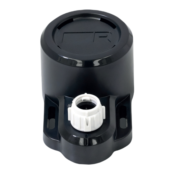
2.2 Product overview The SeaTalkng ® Alarm buzzer accessory is a remote SeaTalkng ® alarm repeater, designed to complement existing and new systems. The buzzer uses an audible alarm (> 85dB(A)) to repeat SeaTalkng ® and NMEA 2000 alarms generated by devices on the SeaTalkng ® network. The buzzer connects to a spur connection on your SeaTalkng ®... -
Page 15: Chapter 3 Installation
Chapter 3: Installation Chapter contents • 3.1 Warnings and cautions on page 16 • 3.2 Installation checklist on page 17 • 3.3 Location requirements on page 18 • 3.4 Product dimensions on page 19 • 3.5 Tools required on page 20 Installation... -
Page 16: Warnings And Cautions
3.1 Warnings and cautions Important: Before proceeding, ensure that you have read and understood the warnings and cautions provided in the Chapter 1 Important information section of this document. -
Page 17: Installation Checklist
3.2 Installation checklist Installation includes the following activities: Installation Task Plan your system. Obtain all required equipment and tools. Site all equipment. Route all cables. Drill cable and mounting holes. Make all connections into equipment. Secure all equipment in place. Power on and test the system. -
Page 18: Location Requirements
3.3 Location requirements Location considerations. When choosing a location for the product, consider the following points to ensure reliable and trouble-free operation: • Access — there must be sufficient space to enable cable connections to the product, avoiding tight bends in the cable. •... -
Page 19: Product Dimensions
3.4 Product dimensions Installation... -
Page 20: Tools Required
3.5 Tools required Product installation requires the following tools: Item Description Quantity Power drill Pozidrive screwdriver Drill bit of appropriate size* Note: * The appropriate drill bit size is dependent on the thickness and material of the mounting surface. -
Page 21: Chapter 4 Cables And Connections
Chapter 4: Cables and connections Chapter contents • 4.1 General cabling guidance on page 22 • 4.2 Connections overview on page 24 • 4.3 SeaTalkng ® power supply on page 25 • 4.4 Buzzer connection overview on page 31 • 4.5 Buzzer connections on page 32 Cables and connections... -
Page 22: General Cabling Guidance
• Unless otherwise stated use only standard cables of the correct type, supplied by Raymarine. • Ensure that any non-Raymarine cables are of the correct quality and gauge. For example, longer power cable runs may require larger wire gauges to minimize voltage drop along the run. - Page 23 • Use only ferrites of the correct type, supplied by Raymarine or its authorized dealers. • Where an installation requires multiple ferrites to be added to a cable, additional cable clips should be used to prevent stress on the connectors due to the extra weight of the cable.
-
Page 24: Connections Overview
4.2 Connections overview Your product includes the following connectors. Connector Connects to: Suitable cables SeaTalk backbone SeaTalk spur cables 2. NMEA 2000 backbone 2. SeaTalk to DeviceNet adaptor cable (A06045) Connecting SeaTalkng ® cables 1. Rotate the locking collar so it is in the unlocked position. 2. -
Page 25: Seatalkng ® Power Supply
4.3 SeaTalkng ® power supply Power is supplied to the product over the SeaTalkng ® backbone. A SeaTalkng ® backbone requires only one 12 V dc power supply, connected to the SeaTalkng ® backbone. This can be provided by one of the following: •... -
Page 26: In-Line Fuse And Thermal Breaker Ratings
The information provided below is for guidance only, to help protect your product. It covers common vessel power arrangements, but does NOT cover every scenario. If you are unsure how to provide the correct level of protection, please consult an authorized Raymarine dealer or a suitably qualified professional marine electrician. - Page 27 Description Connects to: SeaTalkng ® spur connector SeaTalkng ® bus Drain wire Vessel’s common RF ground point. For vessels without a common ground point, connect the drain wire directly to the battery’s negative terminal. Black (negative) wire Battery or distribution panel’s negative terminal.
- Page 28 Positive (+) bar Negative (-) bar Circuit breaker Fuse • In all cases, observe the recommended breaker / fuse ratings provided in the product’s documentation. Important: Be aware that the suitable fuse rating for the thermal breaker or fuse is dependent on the number of devices you are connecting.
- Page 29 Battery connection scenario A: suitable for a vessel with a common RF ground point. In this scenario, if your product’s power cable is supplied with a separate drain wire then it should be connected to the vessel’s common ground point. Battery connection scenario B: suitable for a vessel without a common grounding point.
- Page 30 • NMEA 0400 Installation Standard • ABYC E-11 AC & DC Electrical Systems on Boats • ABYC A-31 Battery chargers and Inverters • ABYC TE-4 Lightning Protection Warning: Product grounding Before applying power to this product, ensure it has been correctly grounded, in accordance with the instructions provided.
-
Page 31: Buzzer Connection Overview
4.4 Buzzer connection overview SeaTalkng ® connector Note: This product is also powered through the SeaTalkng ® connector. Cables and connections... -
Page 32: Buzzer Connections
4.5 Buzzer connections Your buzzer can be connected to a compatible product via a SeaTalkng ® bus (backbone or 5-way connector block). The SeaTalkng ® bus also supplies power to the buzzer. Multiple buzzers can be connected to a system at once. Important: Your MFD requires a separate power supply, do not attempt to power your MFD using the SeaTalkng ®... - Page 33 Multiple MFD network Important: Your MFD requires a separate power supply, do not attempt to power your MFD using the SeaTalkng ® bus. For more information, refer to your MFD installation and operation instructions. Networked MFDs 2. SeaTalkng ® Alarm buzzer 3.
-
Page 35: Chapter 5 Mounting
Chapter 5: Mounting Chapter contents • 5.1 Installing the buzzer on page 36 Mounting... -
Page 36: 5.1 Installing The Buzzer
5.1 Installing the buzzer The buzzer must be mounted to a suitable surface and connected to a 12 V dc SeaTalkng ® bus (backbone or 5-way connector block). The SeaTalkng ® bus also supplies power to the buzzer. Note: * The MFD is shown in the drawing above with a 12 V dc power connection. However, some MFD variants are also compatible with 24 V dc systems. -
Page 37: Chapter 6 System Checks And Troubleshooting
Chapter 6: System checks and troubleshooting Chapter contents • 6.1 LED diagnostics on page 38 • 6.2 Power up troubleshooting on page 40 • 6.3 on page 41 System checks and troubleshooting... -
Page 38: Led Diagnostics
6.1 LED diagnostics Your unit has a diagnostic LED on the front. The LED is used to identify the status of the unit. LED diagnostics light LED Sequence Status Normal operation Green LED on. No power LED off. No data on SeaTalkng ® bus Green LED flashes on and off every 2 seconds. - Page 39 LED Sequence Status Hardware failure detected Green LED flashes on every 1 second. System checks and troubleshooting...
-
Page 40: Power Up Troubleshooting
In the unlikely event that the product’s software has become corrupted, try downloading and installing the latest software from the Raymarine website. 2. On display products, as a last resort, attempt to perform a ‘Power on Reset’. Be aware that this will delete all settings / presets and user data (such as waypoints and tracks), and revert the unit back to factory defaults. - Page 41 Alarm cannot be silenced Possible causes Possible solutions In an autopilot system the "CU Re-connect the display. DISCONNECTED" alarm is generated when 2. Check another display on the network (if a pilot controller display is disconnected. available) for the alarm message. Dismiss alarm. This triggers a repeating audible alarm on the SeaTalkng ®...
-
Page 43: Chapter 7 Maintenance
Chapter 7: Maintenance Chapter contents • 7.1 Service and maintenance on page 44 • 7.2 Routine equipment checks on page 45 • 7.3 Product cleaning on page 46 Maintenance... -
Page 44: Service And Maintenance
7.1 Service and maintenance This product contains no user serviceable components. Please refer all maintenance and repair to authorized Raymarine dealers. Unauthorized repair may affect your warranty. -
Page 45: Routine Equipment Checks
7.2 Routine equipment checks It is recommended that you perform the following routine checks, on a regular basis, to ensure the correct and reliable operation of your equipment: • Examine all cables for signs of damage or wear and tear. •... -
Page 46: Product Cleaning
7.3 Product cleaning Best cleaning practices. When cleaning products: • Lightly rinse or flush with clean, cool fresh water. • If your product has a display screen, do NOT wipe the screen with a dry cloth, as this could scratch the screen coating. •... -
Page 47: Chapter 8 Technical Specification
Chapter 8: Technical specification Chapter contents • 8.1 Technical specification on page 48 Technical specification... -
Page 48: 8.1 Technical Specification
8.1 Technical specification Nominal supply voltage 12 V dc (Supplied by SeaTalkng ®) Operating voltage range 9 V dc to 16 V dc (protected up to 32 V dc) Power consumption 25 mA at nominal supply voltage Sound pressure level (SPL) of audible >85 dB(A) at a distance of 1 meter alarm Environmental... -
Page 49: Chapter 9 Technical Support
Chapter 9: Technical support Chapter contents • 9.1 Raymarine product support and servicing on page 50 • 9.2 Learning resources on page 53 Technical support... -
Page 50: 9.1 Raymarine Product Support And Servicing
You can obtain this product information using diagnostic pages of the connected MFD. Servicing and warranty Raymarine offers dedicated service departments for warranty, service, and repairs. Don’t forget to visit the Raymarine website to register your product for extended warranty benefits: http://www.raymarine.co.uk/display/?id=788. Region Contact •... -
Page 51: Viewing Product Information (Lighthouse™ 2)
• Tel: +45 437 164 64 Russia • E-Mail: info@mikstmarine.ru (Authorized Raymarine distributor) • Tel: +7 495 788 0508 Viewing product information (LightHouse™ 2) You can view information about your unit from the Diagnostics menu on a compatible multifunction display. This option displays information such as product serial number and software version. - Page 52 2. You can view further information about your MFD, or view information about products networked using SeaTalkhs ® and SeaTalkng ® / NMEA 2000, by selecting the Network tab, then: i. to display detailed software information and your MFD’s network IP address, select your MFD from the list.
-
Page 53: 9.2 Learning Resources
9.2 Learning resources Raymarine has produced a range of learning resources to help you get the most out of your products. Video tutorials Raymarine official channel on YouTube: • http://www.youtube.com/user/RaymarineInc LightHouse™ 3 tips and tricks: • http://www.raymarine.com/multifunction-displays/light- house3/tips-and-tricks Video Gallery: •... -
Page 55: Chapter 10 Spares And Accessories
Chapter 10: Spares and accessories Chapter contents • 10.1 Accessories on page 56 • 10.2 SeaTalk ng® cabling components on page 57 • 10.3 SeaTalkng ® cables and accessories on page 58 Spares and accessories... -
Page 56: 10.1 Accessories
10.1 Accessories The following accessories are available: Accessories Item Part number A06042 SeaTalkng ® Elbow spur cable 0.4 m (1.3 ft) -
Page 57: Seatalk Ng® Cabling Components
10.2 SeaTalk cabling components ng® SeaTalk cabling components and their purposes. Connection / Cable Notes Backbone cable (various lengths) The main cable carrying data. Spurs from the backbone are used to connect SeaTalk devices. T-piece connector Used to make junctions in the backbone to which devices can then be connected. -
Page 58: 10.3 Seatalkng ® Cables And Accessories
10.3 SeaTalkng ® cables and accessories SeaTalkng ® cables and accessories for use with compatible products. Part No Description Notes T70134 Starter kit Includes: • 1 x 5 Way connector (A06064) • 2 x Backbone terminator (A06031) • 1 x 3 m (9.8 ft) spur cable (A06040) •... - Page 59 Part No Description Notes A22164 SeaTalk to SeaTalkng ® spur cable 1 m (3.3 ft) A06048 SeaTalk2 (5 pin) to SeaTalkng ® adaptor cable 0.4 m (1.3 ft) A06045 SeaTalkng ® to DeviceNet Allows the connection of NMEA 2000 (Female) adaptor cable 0.4 m devices to a SeaTalkng ®...
-
Page 61: Chapter 11 Supported Alarms
Chapter 11: Supported alarms Chapter contents The SeaTalkng ® Alarm buzzer supports the alarms listed in the following sections of this document. i70 / i70s, LightHouse 2 (LH2) or LightHouse 3 (LH3) columns marked with a symbol indicate that the corresponding alarm will sound on the buzzer. i70 / i70s, LH2 or LH3 columns marked with a symbol indicate that the corresponding alarm will NOT sound on the buzzer (but may sound on a networked i70 / i70s or MFD). -
Page 63: Appendix A Ais Alarms
Appendix A AIS alarms Alarm Generated Generated Supported Supported Supported Severity by (function) by (product) (i70 / i70s) (LH2) (LH3.7+) i70 / i70s, Warning Connection Lost i70 / i70s, Alarm Dangerous Target Warning AIS External AIS receiver AIS External AIS receiver Warning - AIS TX malfunction... - Page 64 Alarm Generated Generated Supported Supported Supported Severity by (function) by (product) (i70 / i70s) (LH2) (LH3.7+) AIS External AIS receiver Warning - AIS transmitter PA fault Warning AIS External AIS receiver - AIS 3V3 alarm AIS External AIS receiver Warning - AIS Rx channel 70 malfunction...
-
Page 65: Appendix B Autopilot Alarms
Appendix B Autopilot alarms Alarm Generated Generated Supported Supported Supported Severity by (function) by (product) (i70 / i70s) (LH2) (LH3.7+) Pilot Warning Autopilot Pilot (NGCC) Alarm Pilot No GPS Autopilot Pilot (NGCC) Alarm Pilot Off Autopilot Pilot (NGCC) Alarm Course Pilot Warning Autopilot Pilot (NGCC) - Page 66 Alarm Generated Generated Supported Supported Supported Severity by (function) by (product) (i70 / i70s) (LH2) (LH3.7+) Wind Autopilot Pilot Alarm Change (a.k.a Pilot Wind Shift) Wind Autopilot Warning Change (a.k.a Pilot Warning Wind Shift) PILOT AUTO Autopilot Pilot (NGCC) Warning DOCKSIDE FAIL PILOT AU-...
- Page 67 Alarm Generated Generated Supported Supported Supported Severity by (function) by (product) (i70 / i70s) (LH2) (LH3.7+) PILOT NO Autopilot Warning Pilot (NGCC) WIND DATA PILOT RATE Autopilot Warning Pilot (NGCC) GYRO FAULT PILOT Autopilot Pilot (NGCC) Warning RUDDER FEEDBACK FAIL PILOT Autopilot Pilot (NGCC)
- Page 68 Alarm Generated Generated Supported Supported Supported Severity by (function) by (product) (i70 / i70s) (LH2) (LH3.7+) Pilot Power- Autopilot Warning Pilot (NGCC) Off or Sleep-Switch Operated or Reset While Engaged Pilot Autopilot Pilot (NGCC) Alarm unexpected reset while engaged Pilot no drive Autopilot Pilot (NGCC) Warning...
-
Page 69: Appendix C Depth Alarms
Appendix C Depth alarms Alarm Generated Generated Supported Supported Supported Severity by (function) by (product) (i70 / i70s) (LH2) (LH3.7+) SeaTalk1 Depth Depth Alarm Anchor Instrument Deep Anchor Depth Depth Alarm - SeaTalkng instrument Deep Depth Depth Depth Warning instrument Shallow Depth Depth... -
Page 70: Appendix D Digital Switching Alarms
Appendix D Digital switching alarms Alarm Generated Generated Supported Supported Supported Severity by (function) by (product) (i70 / i70s) (LH2) (LH3.7+) Digital NXT Master Alarm Generic (Trigentic) Switching (MCU) Digital Switching NMEA2000 Alarm Digital Digital Warning Switching Switching Fuse Tripped Alert Digital Digital... - Page 71 Alarm Generated Generated Supported Supported Supported Severity by (function) by (product) (i70 / i70s) (LH2) (LH3.7+) Generic Digital Warning CZone Switching External Alarm - DC High Voltage Generic Digital Warning CZone Switching External Alarm - DC Low Battery Capacity Generic Digital Warning Switching...
- Page 72 Alarm Generated Generated Supported Supported Supported Severity by (function) by (product) (i70 / i70s) (LH2) (LH3.7+) Generic Digital Warning CZone Switching External Alarm - OI Current Calibration Generic Digital Warning CZone Switching External Alarm - SCI Missing Output Digital Warning Generic Switching CZone...
- Page 73 Alarm Generated Generated Supported Supported Supported Severity by (function) by (product) (i70 / i70s) (LH2) (LH3.7+) Generic Digital Warning CZone Switching External Alarm - AC Load Shed Generic Digital Warning Switching CZone External Alarm - AC Load Shed Very Low Generic Digital Alarm...
- Page 74 Alarm Generated Generated Supported Supported Supported Severity by (function) by (product) (i70 / i70s) (LH2) (LH3.7+) Generic Digital Warning CZone Switching External Alarm - Low CANbus Voltage Generic Digital Warning CZone Switching External Alarm - Blown Fuse...
-
Page 75: Appendix E Engine Alarms
Appendix E Engine alarms Alarm Generated Generated Supported Supported Supported Severity by (product) (i70 / i70s) (LH2) (LH3.7+) (function) Engine Error Engine Alarm Engine Error Engine Alarm - Check Engine Engine Engine Alarm Error - Over Temperature Engine Error Engine Alarm - Low Oil Pressure... - Page 76 Alarm Generated Generated Supported Supported Supported Severity by (product) (i70 / i70s) (LH2) (LH3.7+) (function) Engine Error Engine Warning - Warning Level 2 Engine Error Engine Warning - Power Reduction Engine Error Engine Warning - Engine Comm Error Engine Error Engine Warning - Sub or...
- Page 77 Alarm Generated Generated Supported Supported Supported Severity by (product) (i70 / i70s) (LH2) (LH3.7+) (function) Engine Engines Warning CHECK SAIL DRIVE Engine EGR Engines Warning Error Engine Engines Warning EMER- GENCY STOP Engine EN- Engines Warning GINE COM- Munications ERROR Engine Engines Warning...
- Page 78 Alarm Generated Generated Supported Supported Supported Severity by (product) (i70 / i70s) (LH2) (LH3.7+) (function) Engine MAIN Engines Warning THROTTLE Engine Engines Warning MAINTE- NANCE NEEDED Engine Engines Warning MOVE THROTTLES TO IDLE Engine Engines Warning NETWORK COMM ERROR Engine Engines Warning NEUTRAL...
- Page 79 Alarm Generated Generated Supported Supported Supported Severity by (product) (i70 / i70s) (LH2) (LH3.7+) (function) Transmission Engines Warning error - check transmission Transmission Engines Warning error - over temperature Transmission Engines Warning error - low oil pressure Transmission Engines Warning error - low oil level Transmission...
-
Page 80: Appendix F Environmental Measurements Alarms
Appendix F Environmental measurements alarms Alarm Generated Generated Supported Supported Supported Severity by (function) by (product) (i70 / i70s) (LH2) (LH3.7+) Sea Temp Environmen- Speed Warning High tal Measure- instrument ments Sea Temp Environmen- DPU, MFD Warning High tal Measure- ments Sea Temp In Environmen-... -
Page 81: Appendix G Fishfinder Alarms
Appendix G Fishfinder alarms Alarm Generated Generated Supported Supported Supported Severity by (function) by (product) (i70 / i70s) (LH2) (LH3.7+) Sounder Fishfinder Warning Connection Lost Fish Finder Fishfinder Warning Deep Arrival (previously known as Fishfinder Deep alarm) Fish Finder Fishfinder Warning Shallow Ar- rival (previ-... -
Page 82: Appendix H Fuel Alarms
Appendix H Fuel alarms Alarm Generated Generated Supported Supported Supported Severity by (function) by (product) (i70, i70s) (LH2) (LH3.7+) Low Fuel Fuel Warning Remaining... -
Page 83: Appendix I Heading Alarms
Appendix I Heading alarms Alarm Generated Generated Supported Supported Supported Severity by (product) (i70 / i70s) (LH2) (LH3.7+) (function) No Heading Heading Warning Large Heading Warning Compass: compass AHRS deviation Very large Heading Compass: Warning compass AHRS deviation Heading alarms... -
Page 84: Appendix J Instrument Alarms
Appendix J Instrument alarms Alarm Generated Generated Supported Supported Supported Severity by (function) by (product) (i70 / i70s) (LH2) (LH3.7+) Low battery Instrument Instrument Warning... -
Page 85: Appendix K Mob Alarms
Appendix K MOB alarms Alarm Generated Generated Supported Supported Supported Severity by (function) by (product) (i70 / i70s) (LH2) (LH3.7+) Man Over LifeTag, Emergency Board Other MOB device MOB alarms... -
Page 86: Appendix L Navigation Alarms
Appendix L Navigation alarms Alarm Generated Generated Supported Supported Supported Severity by (function) by (product) (i70 / i70s) (LH2) (LH3.7+) Anchor Navigation Alarm Anti Collision Navigation Warning Large XTE Navigation Alarm Pilot Large Navigation Alarm Waypoint Navigation Navigation Alarm Arrival Per- computer pendicular Passed... -
Page 87: Appendix M Position Alarms
Appendix M Position alarms Alarm Generated Generated Supported Supported Supported Severity by (function) by (product) (i70 / i70s) (LH2) (LH3.7+) Anchor Position Warning GPS Failure Position Warning Position Pilot, MFD, Warning GPS No Fix i70 / i70s Track Full Position Warning Position alarms... -
Page 88: Appendix N Radar Alarms
Appendix N Radar alarms Alarm Generated Generated Supported Supported Supported Severity by (function) by (product) (i70 / i70s) (LH2) (LH3.7+) Dangerous Radar Alarm Target External Radar Radar Warning Dangerous Target External Radar Radar Warning Guard Zone External Lost Radar Radar Warning Target External... -
Page 89: Appendix O Speed Alarms
Appendix O Speed alarms Alarm Generated Generated Supported Supported Supported Severity by (function) by (product) (i70 / i70s) (LH2) (LH3.7+) Boat Speed Speed Speed Warning High instrument Boat Speed Speed Speed Warning instrument Speed alarms... -
Page 90: Appendix P Steering Alarms
Appendix P Steering alarms Alarm Generated Generated Supported Supported Supported Severity by (product) (i70 / i70s) (LH2) (LH3.7+) (function) Manual Off Steering ST60 Alarm Course (a.k.a Compass Pilot Manual Off Course) Off Course Steering Alarm... -
Page 91: Appendix Q Vhf Alarms
Appendix Q VHF alarms Alarm Generated Generated Supported Supported Supported Severity by (function) by (product) (i70 / i70s) (LH2) (LH3.7+) DSC Distress VHF DSC radio Alarm VHF alarms... -
Page 92: Appendix R Wind Alarms
Appendix R Wind alarms Alarm Generated Generated Supported Supported Supported Severity by (function) by (product) (i70 / i70s) (LH2) (LH3.7+) Apparent Wind Wind Warning Wind Angle instrument High Apparent Wind Wind Warning Wind Angle instrument Apparent Wind Wind Alarm Wind Speed instrument High Apparent... - Page 93 Index Installation ...............36 Checklist ............... 17 Schematic diagram ..........17 Accessories .............56 Installation requirements ......... 18 Alarms, AIS ............63, 89 IP address..............52 Alarms, Autopilot .............65 Alarms, Depth............69 Alarms, Digital Switching ......... 70 Alarms, Engine............75 Alarms, Environmental measurements ....80 Knowledge base............53 Alarms, Fishfinder............
- Page 94 SeaTalkng cables ............58 SeaTalkng ® Connecting cables ..........24 Securing cables ............22 Service Center............50 Servicing..............44 Software updates ............ 12 Sound pressure levels..........9 Specification, Environmental parameters ....48 Specification, Nominal supply voltage.....48 Specification, Operating voltage range....48 Specification, Power consumption ......48 Specification, Sound Pressure Level (SPL) ....48 Specification, Supported connection protocols..............48 Strain relief,...
- Page 96 Raymarine Marine House, Cartwright Drive, Fareham, Hampshire. PO15 5RJ. United Kingdom. Tel: +44 (0)1329 246 700 www.raymarine.com a brand by...
Need help?
Do you have a question about the SEATALK NG and is the answer not in the manual?
Questions and answers