
Summary of Contents for Focus Industries Handler I
-
Page 1: Table Of Contents
2” Handler II & III Manifold Venturi Package Breakdown 40 3” Handler III Manifold Venturi Package Breakdown Handler I, II & III Tank Parts Breakdown System Specifications Plumbing Package Assembly Plumbing Package Operation Handler I, II & III Operator’s Manual - October 2008... -
Page 3: Warranty
Warranty Focus Industries Inc. products are warranted for one year from date of purchase against defects in material and workmanship and to perform according to specifications when such products are properly assembled, installed, used and maintained. Warranty is granted to original owner only. -
Page 4: Warranty Registration/Inspection Form
Review Operating & Safety Instructions Oil in Engine the operator’s Manuel content, equipment care, adjustments, safe operation and applicable warranty policy. Date Dealer’s Rep. Signature safe operation and applicable warranty policy. Date Owner’s Signature Handler I, II & III Operator’s Manual - October 2008... -
Page 5: Sign Off Form
Do not operate or allow anyone else to operate this equipment have been instructed in the operation of the equipment. until such information has been reviewed. Annually review this information before season start up. Date Employee Name Employee Signature Handler I, II & III Operator’s Manual - October 2008... -
Page 6: Introduction
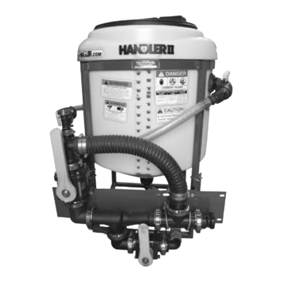
Handler tank. With the proper orientation, the Handler name will be clearly visible on the front of the tank. Handler I, II & III Operator’s Manual - October 2008... -
Page 7: Safety
• Do not put hands into the Handler when adding products. • Wear safety goggles, rubber gloves and protective clothing Think Safety! Work Safely! Handler I, II & III Operator’s Manual - October 2008... -
Page 8: Safety Decal Information
Handler safety decals Think Safety! Work Safely! Handler I, II & III Operator’s Manual - October 2008... -
Page 9: Assembly & Installation
Agitation and rinse valve installation Model Type You have purchased a Handler I, Handler II or Handler III. All components required to install the unit are included in the pack- age except for the fittings used to join the Handler tank to the existing sprayer lines. - Page 10 Fig. H1-4.4 using ¼” x 1” bolts. Do not tighten completely yet. Install smaller ball valve support bracket on to venturi bracket using 5/16” x ¾” bolts. Do not tighten completely yet. (See Fig. H1-4.4) Figure H1-4.6 Handler I, II & III Operator’s Manual - October 2008...
- Page 11 Attach venturi to valve assembly flange with clamp and gas- ket. Do not tighten completely yet. Position discharge end of venturi so it points to the front left (in-between the tabs welded on the frame). (See Fig H1-4.9) Handler I, II & III Operator’s Manual - October 2008...
- Page 12 Figure H1-4.12 Attach completed assembly to venturi bracket (86- H1i15VBPO) using 3/8”x 2 ½” U-bolts (67-UB38-250) (See Fig. H1-4.12) Tighten all bolts and clamps Venturi Nozzle Placement Handler I, II & III Operator’s Manual - October 2008...
- Page 13 MC24 hose clamps (53-75624). Hint: warm hose ends and barbs before trying to install the hose. In addition, silicone spray can be applied to hose ends to make installation easier. Handler I, II & III Operator’s Manual - October 2008...
-
Page 14: Handler Ii Installation
Install 1” MPT X 1” HB 90 (25-HB100-90) on to 1” bulk- head on left side of tank. See figure H2-4.2. (Apply sealant before assembling - see notes on page 37) Figure H2-4.3 Handler I, II & III Operator’s Manual - October 2008... - Page 15 X 1” bolts (67-CSH5C516-1p) – two on the right side and one on the lower left side. Do not tighten completely yet. Hint: if angle frame brackets are not perpendicular to frame tap with a mallet to align them. Handler I, II & III Operator’s Manual - October 2008...
- Page 16 Venturi package assembly and installation Hints: • Lay all parts out first. • Open FC200 and FC220 clamps slightly larger to make as- sembly easier. • Open FC100 clamps completely to make assembly easier. Handler I, II & III Operator’s Manual - October 2008...
- Page 17 Do not tighten completely yet. tighten completely yet. Figure H2-4.10 Figure H2-4.12 Assemble remaining 2” fittings as shown in figure H2-4.10. Assemble 1” fittings as shown in figure H2-4.12. Handler I, II & III Operator’s Manual - October 2008...
- Page 18 Secure with clamps (53-756- Figure H2-4.17 12). Measure, cut, and install 1 ½” PVC suction hose (54-79050) that goes between tank and venturi valve. Secure with clamps (53-75624). See figure H2-4.16 and H2-4.17. Handler I, II & III Operator’s Manual - October 2008...
- Page 19 This may require drill- ing extra holes in plate. Figure H2-4.19 Install 2” Tee (10-11100) to bottom of tank (use pipe seal- ant) see figure H2-4.19. Handler I, II & III Operator’s Manual - October 2008...
-
Page 20: Handler Iii Installation
figure H3-4.4. Use two 1” U-bolts (67-UB025-100) per union. (Apply sealant before assembling - see notes on bracket. Bottom of bracket should be 7” from bottom of page 37) frame. NOTE: Tighten only enough to prevent slipping. Handler I, II & III Operator’s Manual - October 2008... - Page 21 ¼” locking nuts. Do not tighten com- closed position to left when looking at front of valve. pletely yet. Go to next step (Three way valve support bracket installa- tion). Handler I, II & III Operator’s Manual - October 2008...
- Page 22 3 way ball valve (25-MV220BL) as shown in figure H3-4.7 • Start assembly at discharge end and work towards other end Handler I, II & III Operator’s Manual - October 2008...
- Page 23 (use 25-FC220 clamp and 25-200G gasket). Do not tighten completely yet. Install 2 ½ “ U-bolts (67-UB038-250) to hold second as- sembly to intake support plate. See figure H3-4.11. Do not tighten completely yet. Handler I, II & III Operator’s Manual - October 2008...
- Page 24 Assemble manifold venturi package as shown in figure H3- 4.18. Do not tighten completely yet. Figure H3-4.16 Install 2”FPT X 1 ½” hose barb 90 degree fitting on to bot- tom of tank, see figure H3-4.16 Handler I, II & III Operator’s Manual - October 2008...
- Page 25 Install two 4” U-bolts (67-UB038-400) to hold assembly to plate. Do not tighten completely yet. Figure H3-4.22 Assemble 1” fittings as shown in figure H3-4.22. Figure H3-4.20 Handler I, II & III Operator’s Manual - October 2008...
- Page 26 figure H3-4.16. Measure, cut, and install 1 ½” PVC suction hose (54-79050) that goes between tank and venturi valve. Secure with clamps (53-75624). See figure H3-4.17. Handler I, II & III Operator’s Manual - October 2008...
- Page 27 If using a pump/motor combination different than shown in figure H3-4.29 may require repositioning of the pump to di- rect exhaust away from the tank. This may require drilling extra holes in plate. Handler I, II & III Operator’s Manual - October 2008...
-
Page 28: Operation
Review safety instructions annually. Break In Although there are no operational restrictions on the Handler when used for the first time, it is recommended that the follow- ing mechanical items be checked: Handler I, II & III Operator’s Manual - October 2008... - Page 29 Check the plumbing for leaks. Repair all leaks before start- ing. • Review and follow the Pre-Operation checklist for the sprayer. • Check pump engine for oil and top up if necessary. Handler I, II & III Operator’s Manual - October 2008...
- Page 30 Rotaflush valve (Handler III only) Pump suction valve (Optional - Handler II & III only) Handler III valves Handler I valves Optional pump suction valve - Handler II or III Handler II valves Handler I, II & III Operator’s Manual - October 2008...
- Page 31 (See Figure H2-5.2 and H1-5.2) Figure H1-5.1 Handler I Move handle on Main Valve to venturi position to allow water to flow through venturi, (See Figure H1-5.1 and H2- 5.1) Figure H2-5.3 Handler I, II & III Operator’s Manual - October 2008...
- Page 32 When desired sprayer tank volume is achieved, close Main Valve to stop water flow into Handler tank. Valve. • NOTE: rinse water is being continuously sent off to sprayer as rinsing is occurring. Handler I, II & III Operator’s Manual - October 2008...
- Page 33 Handler tank, allowing fresh water from the source tank to When desired sprayer tank volume is achieved, move handle bypass the venturi system and finish filling the sprayer tank. on Main Valve to closed position, (See Figure H2-5.5). Handler I, II & III Operator’s Manual - October 2008...
- Page 34 Figure H2-5.8 jet, (See Figure H2-5.6) Position handle on Pump Suction Valve to draw fresh water, start nurse pump to draw fresh water from water supply tank, (See Figure H2-5.8) Handler I, II & III Operator’s Manual - October 2008...
- Page 35 Add product to water in tank and agitate for as long as required. Close Agitation Valve (See Figure H2-5.6) and position the Main Valve to bypass (This will use the pump to deliver mixture to sprayer). (See Figure H2-5.1) Handler I, II & III Operator’s Manual - October 2008...
-
Page 36: Troubleshooting
This is the weakest point on the container and it cuts up the side of the container allowing for full drainage. See image below for proper puncture location. Handler I, II & III Operator’s Manual - October 2008... - Page 37 See the section of this manual that covers cleaning the tank Contamination in optional recircu- Improper rinsing/cleaning Add a second ball valve on the bottom of the tank to com- lation line pletely isolate the line returning to the pump. Handler I, II & III Operator’s Manual - October 2008...
-
Page 38: Handler I Manifold Venturi Package Breakdown
- 53-75624 MC24SS Hose Clamp 11 25-M220A 2” FP Flange X 2” Male Camlock 23 54-79050 1 1/2” PVC Suction Hose 1.5 ft 12 25-M220CPG90 2” FP Flanged Coupler 90 Degree Handler I, II & III Operator’s Manual - October 2008... -
Page 39: Handler I Threaded Venturi Package Breakdown
22 54-79050 1 1/2” PVC suction hose 3.0 ft 11 25-200A 2” FPT x 2” Male Camlock 23 53-75624 MC24SS hose clamp 12 25-M200FPT 2” Flange x 2” FPT Manifold Fit. Handler I, II & III Operator’s Manual - October 2008... -
Page 40: 2" Handler Ii & Iii Manifold Venturi Package Breakdown
2” FP Flange X 1” Flange Tee 17 25-M220CPG90 2” FP Flanged Coupler 90 35 25-M100PLG 1” Flange Plug 18 25-M200CPG90SH 2” SP Flanged Coupler 90 36 25-SL100-45 1” Street Elbow 45 Degree Handler I, II & III Operator’s Manual - October 2008... -
Page 41: 3" Handler Iii Manifold Venturi Package Breakdown
18 25-HB100 1” MPT X 1” HB 37 25-V20153138 Handle Offset for 25-MV200CF 19 25-HB100-90 1” MPT X 1” HB 90 38 67-CSHC14-2S1 2”L x 1/4” SS Bolt for Handle Handler I, II & III Operator’s Manual - October 2008... -
Page 42: Handler I, Ii & Iii Tank Parts Breakdown
15” hinged polypropylene lid and rim 1 10 30-60974PHK 3/4” FPT x HB 90 - Drilled 5 N/A 11 10-14210 2” anti-vortex fitting 6 25-TF100 1” FPT bulkhead 12 49-PWRF-15 RotaFlush Handler I, II & III Operator’s Manual - October 2008... -
Page 43: System Specifications
Performance data is based on water. • Height: 40” with lid on. • Width: 34” with plumbing (27” diameter without plumbing). • Length: 32” with plumbing only, 53” with pump bracket and pump attached. Handler I, II & III Operator’s Manual - October 2008... -
Page 44: Plumbing Package Assembly
U-bolts provided. Tighten. fresh water, and to remove mix liquids and concentrated chemi- cal solutions from the tank. This appendix to the Handler I, II & III manual gives assembly and operational instructions for the Handler III plumbing package systems offered by Focus Industries. - Page 45 26. Figure H3P-4.5 Assemble 3” plumbing package. (See Fig H3P-4.5) Install plumbing assembly to venturi bracket using three 3/8” x 4” U-Bolts 67-UB38-400. Tighten all bolts and U- Bolts. Handler I, II & III Operator’s Manual - October 2008...
-
Page 46: Plumbing Package Operation
To rinse replace the lid, close valve #3 and turn valve#1 to receive fresh water. Open the valve to the RotaFlush nozzle (not shown) and thoroughly rinse the Handler tank. Handler I, II & III Operator’s Manual - October 2008... - Page 47 If more water needs to be added to the tank, turn valve #1 to receive fresh water. • NOTE: Repeat above steps until desired amount of mix- ture is attained. Handler I, II & III Operator’s Manual - October 2008...
- Page 48 Handler I, II & III Operator’s Manual - October 2008...
Need help?
Do you have a question about the Handler I and is the answer not in the manual?
Questions and answers