Table of Contents
Advertisement
Quick Links
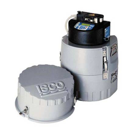
GLS
Sampler
This pocket guide is not intended to replace
the instruction manual provided on CD. Read
the Glacier Manual on CD thoroughly before
operating the sampler.
COPYRIGHT © 2002 by
Isco, Inc., 4700 Superior St., Lincoln,
Nebraska, U.S.A. 68504
Phone: (402) 464-0231
Toll Free: (800) 228-4373
FAX: (402) 465-3022
Part #69-2953-030
Revision A, March, 2003
Advertisement
Table of Contents

Summary of Contents for ISCO GLS
- Page 1 CD. Read the Glacier Manual on CD thoroughly before operating the sampler. COPYRIGHT © 2002 by Isco, Inc., 4700 Superior St., Lincoln, Nebraska, U.S.A. 68504 Phone: (402) 464-0231 Toll Free: (800) 228-4373 FAX: (402) 465-3022...
-
Page 3: Table Of Contents
1.10.1 Positioning the Strainer and Suction Line ... . . 1-12 1.11 Locking the GLS ....1-14 2. Programming 2.1 The Keypad . - Page 4 GLS Sampler 2.4.3 Bottle Volume ... . . 2-7 2.4.4 Number of Samples ..2-8 2.4.5 Sample Volume ... . 2-9 2.4.6 Program Start Time .
-
Page 5: Installation
Sampler Section 1 Installation 1.1 Introduction This pocket guide contains: • Installation instructions, see Section 1.2 • Programming instructions, see Section 2 • Operating instructions, see Section 3... -
Page 6: Sampler Preparation Checklist
GLS Sampler 1.2 Sampler Preparation Checklist The following checklist can be used as a guide to prepare the GLS for each use. 1. Inspect the pump tube. See Section 1.3. 2. Check the discharge tube. See Section 1.4. 3. Install the bottle. -
Page 7: Inspecting The Pump Tube
The housing and rollers should be free from debris. 5. Replace the pump housing cover and tighten the thumbscrews. Note The GLS will display a pump tube warning as part of the View Log screens when it exceeds 500,000 pump counts. -
Page 8: Discharge Tube
GLS Sampler Note The GLS automatically resets the pump tube count to 500,000 after it displays the warning message. Note Isco pump tubes are made from medical-grade Silastic™ tubing. This tubing will not contribute any organic material to the samples. -
Page 9: Installing A Bottle
Section 1 Installation 1.5 Installing a Bottle The base section of the GLS is designed to hold five different types of bottles: • 2.5 gallon (10 liter) Polyethylene • 2.5 gallon (10 liter) Glass • 1 gallon (3.8 liter) Polyethylene (with bottle deck) •... -
Page 10: Installing A Power Source
GLS Sampler 1.7 Installing a Power Source The GLS must be powered by a 12-Volt DC power source. Isco recommends using one of the following Model 900 series power sources: • Batteries - · Model 934 Nickel Cadmium Battery, 4.0Ah ·... -
Page 11: Suction Line And Strainer
4. Power Packs Only - Route the AC line cord though the center section’s Tubing/Cable port. Note If you use a battery to power the GLS, always install a fully charged one before running a program. Note Refer to Isco’s Power Products Guide, P/N 60-9003-092, for a complete description of each power source. -
Page 12: Cutting The Suction Line
GLS Sampler 2. Attach a strainer to the suction line (Section 1.8.1). 3. Connect the suction line to the pump tube (Section 1.8.2). Note The vinyl suction line does contain a very low ppm (parts per million) level of phenols. If this affects your samples, use the Teflon suction line. -
Page 13: Connecting The Suction Line
Section 1 Installation 1.8.3 Connecting the Suction Line Vinyl Suction Line ⁄ ⁄ To connect the -inch (6 mm) or -inch (9 mm) vinyl suction line to the pump tube: Items required: Suction line with strainer attached Tubing coupler 1. Insert the end of the tubing coupler with the black clamp into the upper pump tube. -
Page 14: Connecting External Devices
GLS Sampler 1.9 Connecting External Devices The GLS can be used with external devices that control the sampler pacing, sampler inhibiting, or both. The sampler pacing input can control the rate of sample collection so that it is proportional to the flow rate of a channel. This... -
Page 15: Positioning The Gls
The following points should also be considered: • Level surface - The GLS should be placed on a level surface to prevent tipping or spills. • Support - The surface or mounting method must be able to support the GLS at full capacity. -
Page 16: Positioning The Strainer And Suction Line
• Security - The location may need to provide some degree of security to prevent tampering or vandalism. The GLS can be installed in a manhole using the optional suspension harness (P/N 60-2954-033). Contact your sales representative or Isco for more information. - Page 17 Section 1 Installation eddy or at the edge of flow. Its depth in the stream can also be important. An intake placed at the bottom of the stream may result in excess heavy solids, while placement at the top may result in the opposite. The suction line should always be cut to the shortest possible length.
-
Page 18: Locking The Gls
1.11 Locking the GLS Access to the inside of the GLS can be secured by placing a padlock on the carrying handle. Because the carrying handle must be repositioned before gaining access, locking the... -
Page 19: Programming
Section 2 Programming 2.1 The Keypad On/Off Button – When in the Off state the On/Off button turns the GLS on and places it in the Standby state. In any other state, the On/Off button will place the sampler in the Off state. -
Page 20: Programming The Gls
GLS One-button Programming (see One-button Programming, section 2.3). Go Button – Pressing the Go button places the GLS in the Run state using the current program. 2.2 Programming the GLS There are two ways to program the GLS: •... -
Page 21: One-Button Programming
This sequence of buttons must be pressed within 10 seconds. 2.3.1 Stored Program At all times the GLS holds two programs, the Stored program and the Current program. The Stored and Current program settings may or may not be the same. When you press the Go button, the GLS runs the Current program settings. -
Page 22: Standard Programming
GLS Sampler The GLS is shipped from the factory with the following stored program settings: • Time Paced • 15 Minute Pacing Interval • 9400 ml Bottle Volume - for 2.5 gallon (10 liter) bottles • Take 96 Samples - covers a 24-hour time period •... -
Page 23: Sample Pacing
Section 2 Programming • Number of Samples - Set the number of samples to collect or place the GLS in the Continuous Sampling mode. • Sample Volume - Enter the desired volume to collect at each sample event. • Program Start Time- Without a delay the GLS will always take the first sample when you press the Go button. -
Page 24: Pacing Interval
1 to 9,999. Tip - If you enter an incorrect value with the number-entry buttons, press the Stop but- ton. The GLS restores the original value and waits for a new value. 2. Press the Enter button to accept the new... -
Page 25: Bottle Volume
As shown on the display, acceptable values range from 3500 to 9990 milliliters. The GLS typically uses standard bottles provided by Isco. When using Isco’s standard bottles refer to the chart below for recommended values. -
Page 26: Number Of Samples
GLS Sampler You may use a non-standard bottle in the GLS. When entering the non-standard bottle volume, it is advisable to enter a value less than the total volume. Again, this will reduce the possibility of missed samples and spills. -
Page 27: Sample Volume
Continuous Sampling mode: 1. At the “TAKE XX SAMPLES” display, press the Zero button. 2. Press the Enter button. The GLS is placed in the Continuous Sampling mode and advances to the next programming step. 2.4.5 Sample Volume... -
Page 28: Program Start Time
Suction Line (section 2.4.7). Select the “SET START TIME” to delay the first sample until a programmed time and date. If you select this option the GLS advances to the “FIRST SAMPLE AT” dis- play. FIRST SAMPLE AT: 08:00 3/17/03 2. - Page 29 Note If the programmed start time elapses before running the program, the GLS will take the first sample immediately after the Go button is pressed. If you selected “TIME PACED” in step #1, (section 2.4.1), the GLS advances to the Suction Line setting.
- Page 30 MAXIMUM RUN TIME. • If your sampling protocol does not have this requirement, enter “0” (zero). The GLS will run until it completes the total number of samples. 2-12...
-
Page 31: Suction Line
CALIBRATE TO CHANGE This Suction Line display reports the suction line diameter and length. This information must be correct so that the GLS can deliver sample volumes as programmed. Verify that the diameter and length match the suction line in use. -
Page 32: Storing A Program
One-button programming procedure. Note The stored program settings are held in the sampler’s memory until the software is updated or the GLS is re-initialized. Either of these actions will restore the factory default program settings. 2.6 Setting the Time and Date... -
Page 33: Calibration
2.7 Calibration The GLS can deliver sample volumes repeatable to ±10 ml. The GLS relies on you to enter correct suction line diameter and length values. The GLS uses these values to:... - Page 34 “measure” the liquid volume • Calculate the suction head. By calculating the suction head, the delivered volumes are not affected by varying liquid levels. The GLS automatically calculates the suction head using input from the Liquid Detector. Note Incorrect suction line values or disabling the liquid detector may adversely affect the volume accuracy.
- Page 35 Section 2 Programming SUCTION HEAD 10 ft (0-25 ft) 3. If the liquid detector is disabled, the GLS will ask for a manual or “fixed” suction head since it will not be able to calculate the head. CHECK SAMPLE VOLUME? 4.
- Page 36 GLS Sampler TAKING 200 ml CALIBRATE SAMPLE 6. The GLS goes through a complete sample collection cycle and deposits the sample into the graduated cylinder. VOLUME DELIVERED 200 ml 7. When it has finished collecting the sample, the GLS displays the expected volume.
-
Page 37: Operation
You can start the GLS operation by pressing the Go button. Pressing this button runs the current program. The GLS operation can also be started with the one-button programming sequence. This action will load the stored program settings as the current settings and run the program. -
Page 38: Program Start Times
Go. If a Program Start Time has been programmed, the GLS waits until the this time and date before drawing its first sample. While waiting the GLS display alternates between the screens below. - Page 39 Note The GLS will not “store” samples while it is inhibited. The GLS takes no action at all when it counts down a complete time or flow-pacing interval. Note Sampler Inhibit signal (pin F) requirements - a low (grounded) level of at least 5 seconds inhibits the operation.
-
Page 40: Run State Displays
GLS Sampler 3.2 Run State Displays The GLS updates its display while it is running a program so that you can monitor the status. The Run State displays are listed below. 3.2.1 Collecting a sample As the GLS goes through a sample collection cycle it displays…... -
Page 41: Errors
Section 3 Operation …where “xxx” is the next sample number and “yyy” is the programmed number of samples. If the GLS is in the Continuous Sampling mode, it only displays the next sample number. 3.2.3 Errors If the GLS encounters an error while running a... -
Page 42: Program Completion
The GLS continues to count down the pacing interval while it is paused. Keep in mind that if the count reaches zero the GLS will not take a sample. It records this as a “MISSED SAMPLE - PROGRAM PAUSED” in the log. -
Page 43: Recovering The Sampler
• A GLS with battery, full sample bottle, and ice may weigh as much as 63 pounds (28.6 kg). • The GLS must be kept level to avoid spilling the bottle’s contents. 3.4.2 Preparing the Full Sample Bottle To prepare a full bottle to return to the lab you must first gain access to the sampler’s base. -
Page 44: Viewing The Log
The log can be viewed by selecting the “VIEW LOG” option at the Standby or Paused state displays. As you begin to view the Log, the GLS reports the following: • The number of samples it has collected • Missed samples. The GLS skips this display if there are none to report. - Page 45 Last Calibration Date, Last Programmed Date, Clock Set, and the Sampler ID and Software Revision. The GLS also keeps the current pump count value which is used to determine when to display the pump tube warning. Re-initializing the GLS or updating...
-
Page 46: Errors
ERRORS HAVE OCCURRED The GLS also makes an entry in the Log, which can be viewed later to determine the cause. Possible log entries are: • No liquid detected - The GLS did not detect any liquid. -
Page 47: Grab Samples
Using the number-entry buttons, enter the desired volume (in ml). Press the Enter button to continue. 3. The GLS waits for you to prepare to collect a grab sample. Pull the lower pump tube from the bulkhead fitting. Hold the end of the tube over a container. -
Page 48: Replacing The Pump Tube
“PROGRAM PAUSED” error. 3.7 Replacing the Pump Tube The pump tube is subject to wear during pump operation. It should be replaced when the GLS displays the pump tube warning at 500,000 pump counts, or when inspection of the tube reveals any cracks along its side. - Page 49 Section 3 Operation 7. Isco replacement pump tubes are marked with two black bands. These bands are used to correctly locate the tubing in the liquid detector and the pump. Position the pump inlet, or short end, in the upper groove of the liquid detector.
- Page 50 Note The peristaltic pump and tube will perform the best when you: - Use Isco replacement pump tubes or bulk tubing. - Install the tube properly, aligning the inside edges of the bands with the outside edges of the liquid detector.
Need help?
Do you have a question about the GLS and is the answer not in the manual?
Questions and answers