Advertisement
Series 90
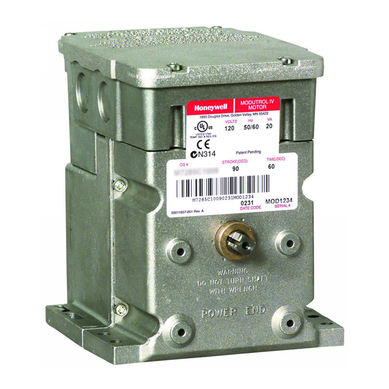
Modutrol IV™ Motors
APPLICATION
The Series 90 Modutrol IV™ Motors are spring return and
non-spring return modulating proportional control motors. Use
these motors with controllers that provide a Series 90 output
to operate dampers or valves.
FEATURES
• Replaces M934A,D, M941, M944A,C,D, M945A,D,F,
M954, M965, and M975 motors.
• Integral junction box provides NEMA 3 weather
protection.
• Integral spring return returns motor to normal position
when power is interrupted.
• Motor and circuitry operate from 24 Vac. Models
available with factory installed transformer, or a field
added internal transformer.
• Quick-connect terminals are standard-screw terminal
adapter is available.
• Adapter bracket for matching shaft height of older
motors is available.
• Motors have field adjustable stroke (90° to 160°).
• Die-cast aluminum housing.
• Integral auxiliary switches are available factory
mounted, or can be field added.
• Nominal timing standard of 30 seconds (90° stroke),
and 60 seconds (160° stroke). Other timings available.
• Spring return motors can operate valve linkages form
power end or auxiliary end shafts for normally closed
or normally open valve applications.
• All models have dual shafts (slotted and tapped on
both ends).
• All models have auxiliary switch cams.
• Fixed torque throughout the entire voltage range.
• Motors are designed for either normally open or
normally closed valves and dampers.
• Field addable interface modules can be mounted in the
junction box to upgrade the motor to Series 70
(electronic) control.
Application ........................................................................
Features ...........................................................................
Specifications ...................................................................
Ordering Information ........................................................
Installation ........................................................................
Settings and Adjustments .................................................
Operation .......................................................................... 10
Checkout .......................................................................... 12
Replacement .................................................................... 12
PRODUCT DATA
Contents
1
1
2
2
5
7
63-2631
Advertisement
Table of Contents

Related Manuals for Honeywell Modutrol IV M934D


Summary of Contents for Honeywell Modutrol IV M934D
-
Page 1: Table Of Contents
Series 90 Modutrol IV™ Motors PRODUCT DATA FEATURES • Replaces M934A,D, M941, M944A,C,D, M945A,D,F, M954, M965, and M975 motors. • Integral junction box provides NEMA 3 weather protection. • Integral spring return returns motor to normal position when power is interrupted. •... -
Page 2: Specifications
If you have additional questions, need further information, or would like to comment on our products or services, please write or phone: 1. Your local Honeywell Automation and Control Products Sales Office (check white pages of your phone directory). 2. Honeywell Customer Care... - Page 3 SERIES 90 MODUTROL IV™ MOTORS TOP VIEW TOP VIEW OF BRACKET 4-7/8 4-1/4 (124) (107) 4-5/8 5-13/16 (116) (148) 5-1/2 2-5/16 (140) (58) 11/16 (17) 13/16 POWER END (20) 1/4 (7) 13/16 (20) 4-7/8 (124) 4-1/16 (103) 1-1/2 (37) 5-9/16 (141) 4-1/16 (103) 1-1/2 (37) JUNCTION...
- Page 4 50017460-001 Internal Transformer; 24/120/230 Vac 50/60 Hz Tulsa, OK 74147-1650 primary, 24 Vac secondary, quick connect terminals. Requires Honeywell 7617DM Coupling. 50017460-003 Internal Transformer; 120 Vac 50/60 Hz primary, 24 Vac secondary, quick connect terminals. Table 5. Modutrol Motor Cross-Reference.
-
Page 5: Installation
SERIES 90 MODUTROL IV™ MOTORS INSTALLATION Use the following guidelines for proper motor mounting: • Always install motors with the crankshaft horizontal. • Mounting flanges extending from motor housing base are When Installing this Product... drilled for 1/4 inch (6.4 mm) machine screws or bolts. •... - Page 6 SERIES 90 MODUTROL IV™ MOTORS STANDARD BOLTS (4) BOLTS PROVIDED (4) WIRING MOTOR ADAPTER BRACKET EQUIPMENT BASE 1 #12 OR 1/4" ZINC PLATED MACHINE SCREWS OR BOLTS M18999 NON-SPRING RETURN SPRING RETURN Fig. 3. Mounting the motor with an adapter bracket. Damper Linkages The motor does not include a crank arm.
-
Page 7: Settings And Adjustments
SERIES 90 MODUTROL IV™ MOTORS Wiring 135 OHM MOTOR POTENTIOMETER CAUTION Electrical Shock or Equipment Damage Hazard. Can shock individuals or short equipment circuitry. Disconnect power supply before installation. TRANSFORMER IMPORTANT (HOT) All wiring must agree with applicable codes, ordinances and regulations. POWER SUPPLY. - Page 8 SERIES 90 MODUTROL IV™ MOTORS To set the stroke between 90° and 160° follow the procedure below: 1. Turn the stroke potentiometer fully CW , using a 1/8 in. straight-blade screwdriver to set 160° stroke. LINEARIZATION 2. Set the maximum position using an external 135 Ohm POTENTIOMETER potentiometer.
- Page 9 SERIES 90 MODUTROL IV™ MOTORS Motors with factory-added auxiliary switches are shipped in the CAUTION closed position (fully counterclockwise, as viewed from the power end). Auxiliary cam default actuates the switches 30° Careless Installation Hazard. from full open with a 1° differential. With the motor in the closed Use of excessive force while adjusting cams (fully counterclockwise) position, the auxiliary switch breaks damages the motor.
-
Page 10: Operation
SERIES 90 MODUTROL IV™ MOTORS OPERATION Use Series 90 Modutrol IV Motors for standard Series 90 operation (see Table 7): 1. Two potentiometers, one in the controller and one in the motor, along with the motor resistor network, form a bridge circuit. - Page 11 SERIES 90 MODUTROL IV™ MOTORS 1/8 INCH RIGHT/INNER 1/8 INCH STRAIGHT-BLADE RIGHT/INNER AUXILIARY STRAIGHT-BLADE SCREWDRIVER AUXILIARY SWITCH SCREWDRIVER SWITCH SLOW RISE SLOW RISE PORTION PORTION INNER INNER (APPROX. (APPROX. AUXILIARY AUXILIARY 10 DIFF.) FAST RISE PORTION FAST RISEPORTION 10 DIFF.) (APPROX.
-
Page 12: Checkout
220738A to raise the motor shaft to the appropriate height. Valve applications with a Q5001 Linkage do not require the 220738A Adapter Bracket. To operate Honeywell V5011 two- way or V5013 three-way valves through full stroke, use a 160° stroke motor.