Table of Contents
Advertisement
Advertisement
Table of Contents

Summary of Contents for Songmao SM100-C(III)
- Page 1 SM100-C(Ⅲ) HART-USB MODEM USER MANUAL...
-
Page 2: Table Of Contents
Contents 1 SM100-C(Ⅲ)Introduction.........................- 3 - 1.1 Product Introduction........................- 3 - 1.2 Product Specifications.........................- 3 - 1.3 Product Features..........................- 3 - 1.4 Main Parameters..........................- 3 - 2 SM100-C(Ⅲ)Diagram and LED Functions..................- 4 - 2.1 Diagram............................- 4 - 2.2 Connection Diagram........................- 4 - 2.3 LED Indications.......................... - Page 3 Statement: Copyright © 2017 SMDZNET. All Rights Reserved. Please read the manual intensively before using the product. SMDZNET does not warrant or accept any liability whatsoever in respect of any damage towards the product unless following the instructions. SMDZNET provides the manual for instructions. Specifications and information contained in this manual are furnished for informational use only, and are subject to change at any time without notice, and should not be construed as a commitment by SMDZNET.
-
Page 4: Sm100-C(Ⅲ)Introduction
1.1 Product Introduction The SM100 - C is a HART intelligent communicator designed by JIAXING SONGMAO and complied with the industrial standard. It communicates with any manufacturer of HART instruments, such as Rosemount, E + H, Siemens, Cologne, Yokogawa, SIC etc. -
Page 5: Sm100-C(Ⅲ)Diagram And Led Functions
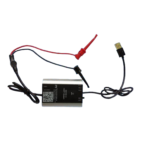
2 SM100-C (Ⅲ) Diagram and LED Functions 2.1 Diagram Imported gold-plated port Imported gold-plated hook design, highlighted the high quality 2.2 Connection Diagram ● Communication cable: Black USB cable (48cm),using for communication between SM100-C and PC, and provide power supply to SM100-C. - Page 6 Without Built-In 24V or 250Ω Resistance With Built-In 24V and 250Ω Resistance...
-
Page 7: Led Indications
2.3 LED Indications ● POW Power LED: Constant lighting when normal communication ● TXD Communication LED: Blinking when data transfers ● RXD Communication LED: Blinking when data receives... -
Page 8: Configuration Software Functions And Operation
3 Configuration Software Functions and Operation 3.1 Communicating Connection 1)Connecting to HART instrument Please take the wiring diagram 2.2 for reference. According to the HART instrument, you can turn the HART change-over switch to the proper position, then connect the Test cable to the HART instrument. 2)Connecting to Serial port Please take the wiring diagram 2.2 for reference. -
Page 9: Online Test
3.2 Online Test 3.3 Instrument IO Correction... -
Page 10: Basic Parameters Configuration Of Instrument
3.4 Basic Parameters Configuration of Instrument 3.5 Basic Information of Instrument 3.6 Parameters Configuration of Temperature Transmitter... -
Page 11: Differential Pressure And Multivariable Transmitter
3.7 Differential Pressure and Multivariable Transmitter... -
Page 12: Wifi Virtual Serial Port Creation
4 WIFI Virtual Serial Port Creation 4.1 Cable Connection You can switch the seral port to WIFI virtual serial port connector, and then connect USB cable with the charger to supply power. 4.2 Wireless Hotspot Connection 1)Search for the wireless network, and choose the wireless hotspot SM100 - C, then click Connect. 2)Configure the IP address for the wireless hotspot and modify it to the same network segment 192.168.0.#. -
Page 13: Virtual Serial Port Creation
4.3 Virtual Serial Port Creation You can start the virtual serial port configuration software, and click Add, and tap in the information of virtual serial port configuration in the pop-up window, then click OK to accomplish the creation for the virtual serial port. The serial port information would be displayed in the main window. -
Page 14: Service And Warranty Information
5 Service and Warranty Information 1. The warranty period for the product is 36 months with normal operation conditions from the date of purchase by end-customers. 2. The company warrants the Product to be free from defects in workmanship and technology for the Warranty Period. 3.
Need help?
Do you have a question about the SM100-C(III) and is the answer not in the manual?
Questions and answers