
Related Manuals for GSE Agrifeed 5500


Summary of Contents for GSE Agrifeed 5500
- Page 1 Agrifeed Model 5500 Digital Weight Indicator Reference Manual Issue AD Standard Scale & Supply Company 25421 Glendale Avenue Redford, MI 48239 313-255-6700 www.standardscale.com...
- Page 2 Preface We at GSE wish to thank you for selecting the Agrifeed 5500 Digital Weight Indicator for your weighing needs. The Agrifeed 5500 continues the GSE tradition of Excellence in Weighing Technology. When properly installed and maintained, the Agrifeed 5500 will provide many years of reliable, accurate performance.
-
Page 3: Table Of Contents
Table of Contents SECTION 1: INTRODUCTION ............1 ..............1 SING THIS ANUAL .............. 2 PERATOR NTERFACE ............2 EIGH PERATION ..................3 EYPAD ............. 4 TANDARD UNCTIONS ................4 ARRANTY ................ 5 PECIFICATIONS SECTION 2: INSTALLATION ............7 ................7 NPACKING ................ - Page 4 SECTION 4: RECIPE SETUP ............41 ......... 41 CCESSING THE ECIPE ATABASE ..............42 DDING A ECIPE 4.2.1 Recipe Pre-Alarm ............43 4.2.2 Weight Entry Method ............44 4.2.3 Ingredient Selection ............45 ..............46 DITING A ECIPE ..............46 ELETING A ECIPE ..............
-
Page 5: Section 1: Introduction
Conventions Used In This Manual The GSE Agrifeed 5500 Digital Weight Indicator, hereafter referred to as the Agrifeed 5500, is capable of displaying alpha characters in either upper or lower case. For ease of reading, this manual uses conventional capitalization when referencing Agrifeed 5500 prompts. -
Page 6: Operator Interface
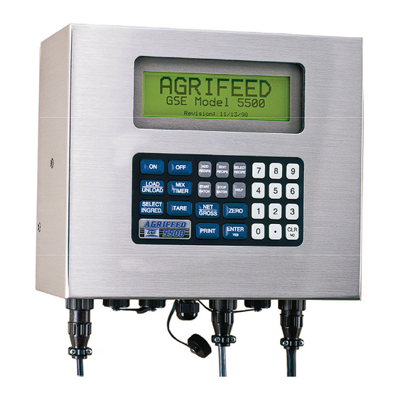
Upon power-up, the back-light and all pixels illuminate momentarily for a display test. The indicator then displays the Agrifeed GSE Model 5500 revision screen followed by the Operator ID? prompt (see Figure 1). Key in the operator ID number and press [ENTER], or press only [ENTER] to bypass the prompt. -
Page 7: Keypad
Table 2: Annunciators Annunciator Indication When Illuminated →0← Displayed weight is at center-of-zero (± ¼ display graduation). Gross The displayed value represents the current gross weight. The displayed value represents the current net weight. The displayed value is represented in pounds. The displayed value is represented in kilograms. -
Page 8: Standard Functions
In the event of a product failure due to materials or workmanship, GSE will, at its discretion, repair or replace the product. Always ensure proper installation and grounding. Never weld around the Agrifeed 5500 or load cells. Contact your GSE Agrifeed distributor for further details. -
Page 9: Specifications
1.7 Specifications PERFORMANCE Full Scale (F.S.) Selectable 0 to 999,990 Resolution 20-bit A/D converter, 100,000d displayed ±500,000d internal A/D Conversion 60 Hz Zero Track 0d – 10.0d Operating Temperature -30°C to +65°C Units of Measure lb, kg, tons ELECTRICAL Power Requirement Input: 10.5 –... - Page 10 This page is intentionally left blank...
-
Page 11: Section 2: Installation
The Agrifeed 5500 Stainless Steel enclosure is designed to NEMA 4X (IP66) type specifications. 2.2.2 Rear Panel Mounting The standard enclosure is designed to attach to an existing stand for mounting. Note that the stand shown in Figure 3 is not supplied by GSE. Figure 3: Rear Panel Mounting Screws... -
Page 12: Swivel Mounting (Optional)
2.2.3 Swivel Mounting (Optional) The optional swivel mounting bracket allows the enclosure to be securely fastened to another surface. The bracket is attached to the indicator with four thumbscrews two of which are used to lock the swivel for optimal viewing angle. -
Page 13: Audit Trail
The seal will pass through two back panel screws as shown in Figure 5. Figure 5: Legal for Trade Sealing Method 2.3.2 Audit Trail Three separate incrementing, non-resetable audit trail parameters are used to indicate changes to various parameters, P60201 – OIML, P60203 –... -
Page 14: Load Cell Connection
2.4.1 Load Cell Connection A high quality cable with braided shield is recommended. Use a four- conductor, 16 to 24 AWG stranded wire cable for load cell or summing box connections. 2.4.2 Printer Port Connection The printer port is a RS232 bi-directional serial port that can be connected to a printer or computer. -
Page 15: Remote Key Connection
2.4.4 Remote Key Connection A remote key may be connected to the Agrifeed 5500 to provide remote activation of TARE, ZERO, PRINT/ADVANCE and PRINT & TARE functions. The connection for the remote key input is between pin 4 of the power connector and ground (pin 2). -
Page 16: Alarm Out Connection
2.4.6 Alarm Out Connection This connection is used in conjunction with the [MIX TIMER] key. When the mix timer is not active pin 3 has a floating output. When the mix timer is active (i.e. counting down) pin 3 is pulled high to the supply voltage. -
Page 17: Section 3: Configuration
Section 3: Configuration 3.1 Password A password must be entered for full access to all setup parameters. The password routine may be bypassed by pressing [ENTER] without entering a password. Bypassing the password allows access to only Quick Menu items listed in section 3.2. 3.1.1 Entering a password An asterisk (*) is displayed in place of each password keypress. -
Page 18: Quick Menu
If the password entered in step 5 is correct, “New Password Saved!” is displayed briefly before returning to the weigh mode. 3.2 Quick Menu The Quick Menu provides access to data logger, display contrast, display back-light and remote display back-light settings. A password is not required to access the Quick Menu. -
Page 19: Print Setup
SCALE SETUP COMM SETUP MEMORY MANAGER REMOTE SETUP INGREDIENT SETUP CALIBRATION Figure 11: Setup Category Headings 3.3.1 Print Setup A print setup may be done from the SCALE SETUP, COMM SETUP, MEMORY MANAGER, REMOTE SETUP and INGREDIENT SETUP. If the print key is pressed from any of these menus, the parameters within that menu will be printed. -
Page 20: Scale Setup
3.3.2 Scale Setup Access the Scale Setup as described in section 3.3. Table 6 describes the Scale Setup parameters. SETUP MENU SELECTION SCALE SETUP [YES]=Access [NO]=Next [HELP]=Exit Figure 12: Setup Menu Selection - Scale Setup To navigate the Scale Setup selections: Press [YES] to advance to the next parameter. - Page 21 Table 6: Scale Setup Menu Parameters Parameter Description Selections 0-100% Sets the level of contrast (or darkness) of CONTRAS in 5% intervals. characters on the display. T SETUP *55% 0-100% BACKLIG Sets the display back-light brightness. in 10% intervals. HT SETUP *50% RECIPE PRE-ALARM: Pre-Alarm based on *COMMON PRE-...
-
Page 22: Communication Setup
Parameter Description Selections Defines the amount of instability in terms of 0.5, 1-5, 10 number of divisions that will constitute MOTION divisions, motion. Presence of motion will delay ZERO, SETUP TARE or ingredient Auto-Advance until *1.0 motion ceases. Determines how quickly the indicator will MINIMUM, respond to a change in weight. - Page 23 Example: To enable the CUSTOM PRINT HEADER: 1. From the COMM SETUP screen, press [YES] twice. 2. Press [NO] to toggle between ENABLED and DISABLED 3. Press [HELP] twice to save changes and exit the setup mode. Table 7: Communication Setup Parameters Parameter Description Selections...
- Page 24 Parameter Description Selections *XON/XOFF, COMM Sets handshaking for the BOTH, HANDSHAKE communications port. NONE, CTS/RTS 300,600,1200,2400,480 PRINT BAUD Sets the baud rate for the printer 0, *9600,19200 baud. RATE port. *8/NONE/1, Sets the protocol for the printer 8/ODD/1, PRINT port. 8/EVEN/1, 8/NONE/2, PROTOCOL (data bits / parity / stop bits)
- Page 25 Moves right Moves left to Selects the to next previous character under character character the cursor arrow Enters header text Deletes the last and completes entry character of the header text 3.3.3.2 Print Styles There are seven selectable print styles and one custom print format available within the Agrifeed 5500.
- Page 26 03:31 pm 04/04/07 TICKET# 1234567 ID#: 12345 ------------------ 03:30 pm 04/04/07 2090 lb Gross RECIPE# 00 lb Tare PEN# 12345 2090 lb AMOUNT 2010 lb Style #1 Style #2 2090 lb Gross 03:33 pm 04/04/07 00 lb Tare 2090 lb 2090 lb Gross Style #3...
-
Page 27: Memory Manager Setup
3.3.4 Memory Manager Setup Access the Memory Manager Setup as described in section 3.3. Table 8 describes the Memory Manager Setup parameters. SETUP MENU SELECTION MEMORY MANAGER [YES]=Access [NO]=Next [HELP]=Exit Figure 15: Setup Menu Selection - Memory Manager To navigate the Memory Manager Setup selections: Press [YES] to advance to the next parameter. - Page 28 Table 8: Memory Manager Setup Menu Parameters Parameter Description Selections Used to transfer recipe/pen information UNLOAD from the data logger to the Agrifeed 5500 DATA (unload data logger), or to transfer history LOGGER, DATA information to the data logger from the *LOAD DATA LOGGER AGRIFFEED 5500 (load data logger).
-
Page 29: Remote Display Setup
be lost as new information is recorded. Refer to the MEMORY MANAGER section to clear the history database. 3.3.5 Remote Display Setup Access the Remote Display Setup as described in section 3.3. Table 9 describes the Remote Display Setup parameters. SETUP MENU SELECTION REMOTE SETUP [YES]=Access... -
Page 30: Ingredient Setup
During normal operation the remote display will echo the gross or net weight as displayed on the Agrifeed 5500. During the load/unload process the remote display will show the gross for two seconds between the change of ingredients or pens. It will then toggle between the name of the current ingredient or pen and the target net weight until motion occurs. - Page 31 To key in an ingredient number, simply type the two-digit ingredient number to display the selected ingredient. EXAMPLE: To access ingredient #8, key in [0] [8] or [8] [ENTER]. To access ingredient #15, key in [1] [5]. INGREDIENTS [15] | Key-in Ingred#, 15 OATS | Press [Enter].
- Page 32 Scroll Scroll Down 3.3.6.2 Naming Ingredients Ingredients must be named before they can be selected for a recipe. To name or rename an ingredient: Access the Ingredient Setup as described in section 3.3. Select the desired ingredient number as described in section 3.3.6.1.
- Page 33 Moves right Selects the Moves left to to next character under previous character the cursor arrow character Enters name and Deletes the last completes entry character of the ingredient name Press [ENTER] to save the name and proceed to the Ingredient Pre-Alarm screen (see Figure 22).
- Page 34 INGREDIENT PRE-ALARM 000000 lb KEY-IN PRE-ALARM VALUE [ENTER]=Accept Value [CLR]=Delete Figure 22: Ingredient Pre-Alarm Screen NOTE: If the PRE-ALARM METHOD parameter in the scale setup is set to “COMMON PRE-ALARM”, then the indicator disregards the Ingredient Pre-alarm weight and instead uses the PRE-ALARM WEIGHT specified in the scale setup for all ingredients.
-
Page 35: Calibrate Mode
3.3.7 Calibrate Mode The Calibration Mode is used to calibrate the Agrifeed 5500 scale system to a known weight value, thus establishing an accurate weight indication throughout the weighing range. Access the Calibration selection as described in section 3.3. From the Calibration Setup Menu Selection, press [YES] to access the calibration routines (see Figure 24). - Page 36 Zero? Calibration Mode Figure 24: Calibration Mode There are six Calibration Mode selections as described below: Most common calibration procedure used to "New Zero?" establish a new zero (no load) and span (test load) calibration reference. Allows a span re-calibration without removing "Last Zero?"...
- Page 37 3.3.7.1 New Zero This is the most common calibration procedure used to establish a new zero (no load) and span (test load) calibration reference. Use this method for first-time calibration and complete re-calibration. To access "New Zero?" calibration from the weigh mode: Access the Calibration Setup Menu Selection as described in section 3.3.
- Page 38 3.3.7.2 Last Zero This procedure allows span re-calibration without removing the applied test weight. The last zero established by pressing [ZERO] from the weigh mode will be used as the zero reference for this procedure. To access " Last Zero?" calibration from the weigh mode: Remove all weight and press [NET\GROSS] then [ZERO] to establish a gross zero reference.
- Page 39 3.3.7.3 Temporary Zero This procedure is used to recalibrate without establishing a new zero. Calibration can be performed without removing the currently applied gross load. A temporary zero is established so additional test weight can be added during calibration. The original zero reference determined during the previous calibration is not affected.
- Page 40 3.3.7.4 Only Zero This procedure is used for zero calibration only and is primarily used for correcting the zero reference after adding or removing dead-load from the scale. To access " Only Zero?" calibration from the weigh mode: Access the Calibration Setup Menu Selection as described in section 3.3.
- Page 41 3.3.7.5 Calibration Reset This procedure adjusts the zero and gain factors of the A/D amplifier. Normally, a Cal Reset is performed if the amplifier is locked in at an extremely high gain factor and will not allow a new calibration to be performed due to an over-load or under-load condition.
- Page 42 3.3.7.6 Known Load Cell Out This procedure is used to calibrate without test weights. The mV/V rating and capacity for each loadcell must be known. To access "Known LCOut" from the weigh mode: Access the Calibration Setup Menu Selection as described in section 3.3.
- Page 43 12. The display shows “CAL OK?” suggesting that the calibration is acceptable. Press [YES] at the “CAL OK?” prompt to accept the calibration. 13. Press [NO] at the “CAL OK?” prompt to repeat the calibration. 14. Once the calibration is accepted in step 5, press [ENTER] at the ENTER=SAVE prompt and again at the ENTER=EXIT prompt to save the new calibration and exit the calibration mode.
-
Page 44: Mix Timer
3.3.8 Mix Timer This feature provides an output to control a mixer and audible alarm at the end of a mixing procedure (see Figure 25). 00:00:00 Enter Mix Time Figure 25: Mix Time Entry Press [MIX TIMER] after loading a recipe. Display shows “Enter Mix Time”. -
Page 45: Section 4: Recipe Setup
Section 4: Recipe Setup This section describes how to setup the recipe database. The Agrifeed 5500 is capable of storing a combination of 500 recipes/ingredients. 4.1 Accessing the Recipe Database Press [SELECT RECIPE] and the display will change from the weigh mode to the Main Recipe screen (see Figure 26: Main Recipe Screen ). -
Page 46: Adding A Recipe
Press [HELP] to exit the Main Recipe screen. The recipe identified in the upper-right corner becomes the recipe selected for loading and unloading. 4.2 Adding a Recipe To add a recipe to the recipe database: Press [ADD RECIPE] from the weigh mode. The display shows ‘Searching…’... -
Page 47: Recipe Pre-Alarm
Moves left to Moves right Selects the previous to next character under character character the cursor arrow Enters name and Deletes the last completes entry character of the recipe name Press [ENTER] to save the name and proceed to the Recipe Pre-Alarm screen as described in the following section. -
Page 48: Weight Entry Method
RECIPE PRE-ALARM 000000 lb KEY-IN PRE-ALARM VALUE [ENTER]=Accept Value [CLR]=Delete Figure 28: Recipe Pre-Alarm NOTE: If the PRE-ALARM METHOD parameter in the scale setup is set to “COMMON PRE-ALARM”, then the indicator disregards the Recipe Pre-alarm weight and instead uses the PRE-ALARM WEIGHT specified in the scale setup for all recipes. -
Page 49: Ingredient Selection
4.2.3 Ingredient Selection Ingredients are assigned when adding or editing recipes. The Ingredient Selection screen (see Figure 29) will appear immediately after selecting the weight entry method described in the previous section. 1st Ingredient CORN SILAGE USE [SELECT INGRED] TO ASSIGN/CHANGE [ENTER]=Next [HELP]=Exit Figure 29: Ingredient Selection Screen... -
Page 50: Editing A Recipe
Following the target entry, the display prompts for the selection of another ingredient. Repeat the Ingredient Selection procedure for each additional ingredient required. After all required ingredients have been entered, press [HELP] at the Ingredient Selection screen (without selecting another ingredient) to exit and save the recipe. 4.3 Editing a Recipe The procedure for editing a recipe is much the same as adding one. -
Page 51: Printing Recipes
4.5 Printing Recipes A list of all named recipes can be printed from the Recipe Selection screen. To print recipes: Press [SELECT RECIPE] to access the recipe list. Press [PRINT] then, Press [1] as prompted to print only the current recipe. Press [2] as prompted to print all recipes. - Page 52 This page is intentionally left blank...
-
Page 53: Section 5: Load / Unload Operation
Section 5: Load / Unload Operation The Agrifeed 5500 is capable of loading and unloading recipes by the touch of the button. Also the indicator is also capable of loading a single ingredient batch using a default recipe ‘RECIPE 00’. 5.1 Loading Ingredients When loading, ingredients can be specified individually or recalled from a recipe. -
Page 54: Loading Process
PERCENT/LOAD – Key in the desired batch target. The target weight for each ingredient is automatically calculated based on the ingredient’s percentage of load. The display shows the first ingredient to load. Press [START BATCH] to begin the loading process (see section 5.1.3). -
Page 55: Advancing Ingredients
5.1.4 Advancing Ingredients To manually advance ingredients: Press [SELECT INGRED]. This records the loaded net weight of the previous ingredient, deletes the ingredient from the loading list, then waits for you to press [START] to begin the loading process for the next ingredient. -
Page 56: Selecting Pens From A List
5.2.2 Selecting Pens from a List This procedure is only used in conjunction with a pen routine list configured by the AGRIDATA Recipe Management PC software. To unload pens from a routine list: Make sure the Agrifeed 5500 is in the UNLOAD mode – if it is in the LOAD mode, press [UNLOAD]. -
Page 57: Advancing Pens
5.2.4 Advancing Pens Press [SELECT INGRED] to advance to the next pen. This records the unloaded net weight of the previous pen, deletes the pen from the routing list, then waits for you to press [START] to begin the unload process for the next pen. - Page 58 RECIPE NOT COMPLETE! Do you wish to cancel loading the Remaining ingredients? [YES] / [NO] Selecting “YES” clears the load and returns to the weigh mode. Selecting “NO” exits to the weigh mode and the LOAD will remain highlighted until the batch is complete. If a pen routing list is loaded or an unload is not complete, the UNLOAD will be highlighted.
-
Page 59: Section 6: Troubleshooting
Section 6: Troubleshooting This section of the manual provides information on error messages, troubleshooting and servicing the Agrifeed 5500 indicator. 6.1 Operational Mode Error Messages Message Description 02 UnderLoad! Input signal less than negative full scale. If this is due to excessive loading, reduce the load. -
Page 60: Hardware Problem Error Messages
29 PIN error This message will appear on power-up or setup if the ram is corrupted in the PIN section. Call GSE Distributor. The access code is then defaulted to the manufacturer (GSE) access code. Also refer to Error 11. -
Page 61: Reload Agrifeed 5500 Custom Program
6.2.1 Reload Agrifeed 5500 Custom Program If you experience a Code 26 error or Code 60 (New Eprom) on the Agrifeed 5500 unit, the following steps will reload the program back into the indicator. Please be advised that reloading this program may take several minutes to complete. -
Page 62: Calibration Error Messages
Verify that correct entries have been made for the scale capacity in Section 3.3.2 and for the calibration weight. Call a GSE distributor. 31 F.S.<.1mVv The entered calibration weight, together with the currently applied signal, indicates that the full scale signal will be less than the allowed minimum of the indicator. -
Page 63: Communication Error Messages
This indicates that the Agrifeed 5500 did not check its receive data register in time, thus missing a character. If this error should occur, please notify your GSE dealer or the factory. To prevent the problem, try reducing the BAUD RATE. The "X" in the error message will be over-written with the associated serial port number. -
Page 64: A/D Calibration Procedure
However, if the values stored at parameters P61110 – P61121 appear to be reset to 0.00000 and/or 1.00000, then A/D re-calibration is necessary. Contact GSE or your local authorized GSE distributor for more information on this procedure. WARNING! There are no user-serviceable items in the Agrifeed... -
Page 65: Section 7: Agrifeed 5500 Option Kits
Section 7: Agrifeed 5500 Option Kits 7.1 Peripheral Options for the Agrifeed 5500 The capabilities of the Agrifeed 5500 can be expanded with the use of one or more option kits. This section shows the installation procedures for these options. Available options for the Agrifeed 5500 include the following: Swivel Bracket Kit Remote Display... -
Page 66: Swivel Bracket Installation
Figure 34: Swivel Bracket Installation Installation Instruction Comments Unpack the Swivel Bracket Option. GSE part # 44-25-35537 Mount Swivel Bracket on flat surface Be sure that when mounting the bracket by securing it through the four to a surface it is mounted upright as mounting holes. -
Page 67: Remote Display Option
The cable connecting the Agrifeed 5500 to the Agrifeed 1500 should not exceed 250 ft (76.3m). A 4-twisted pair conductor Teflon cable (GSE part number 22-10-4660), or a 4-twisted pair conductor PVC cable (GSE part number 22-10-4665) is recommended. - Page 68 The Agrifeed 5500 Remote Display connector, an 8 pin receptacle, uses a socket mating plug (GSE part number 26-20-1160). When matching the sockets of the plug to the pins of the receptacle, be sure to reference the pin-out labeled on the bottom of the Agrifeed 5500 enclosure.
-
Page 69: Agridata Recipe Management Software
TARE, ZERO AND PRINT & TARE functions remotely. The receiver mounts internally inside of the Agrifeed 5500. 7.1.5 RF Link A wireless solution to transfer data such as recipes and pen routing. Contact your GSE Agrifeed distributor for information on the equipment suitable for your application. - Page 70 WI-150 Ultra Low-Power Weight Indicator Service Manual...
- Page 71 WI-150 Ultra Low-Power Weight Indicator Service Manual...
- Page 72 Standard Scale & Supply Company 25421 Glendale Avenue Redford, MI 48239 313-255-6700 www.standardscale.com Agrifeed 5500 Reference Manual Issue AD 39-10-35715...
Need help?
Do you have a question about the Agrifeed 5500 and is the answer not in the manual?
Questions and answers