Table of Contents
Advertisement
Quick Links
Advertisement
Table of Contents

Subscribe to Our Youtube Channel
Related Manuals for Logos Celena X

Summary of Contents for Logos Celena X
- Page 1 USER MANUAL www.logosbio.com LBSM-MD-ML-CLX-001 VC1812-01...
- Page 2 Do not disassemble the device on any occasion as this will invalidate your warranty. TRADEMARKS The trademarks used in this document are the property of Logos Biosystems, Inc. unless otherwise specified. LED Filter Cubes are LTC Licensed Products provided under an intellectual property license from Life Technologies Corporation.
-
Page 3: Table Of Contents
Table of Contents Getting Started ........................................4 Product contents Product description CELENA® X High Content Imaging System CELENA® X Controller Software Setting up Unpacking Connections Shipping guard/restraints Turn on the CELENA® X Install filter cubes and objectives Shut down the CELENA® X CELENA®... - Page 4 Maintenance ........................................37 General care Change filter cubes Change objectives Adjust objective correction collars Appendix A: Troubleshooting ....................................40 Image quality Explorer Mechanical Appendix B: Specifications ...................................... 41 CELENA® X High Content Imaging System Appendix C: Safety Information ..................................... 42 Instrument safety Personal safety Instrument symbols...
-
Page 5: Getting Started
1. Getting Started 1.1 Product contents Your CELENA® X is shipped with the following components: CELENA® X High Content Imaging System Camera module (installed as ordered) Condenser (installed as ordered) Laser autofocus module (installed as ordered) Filter cubes (installed as ordered) ... -
Page 6: Product Description
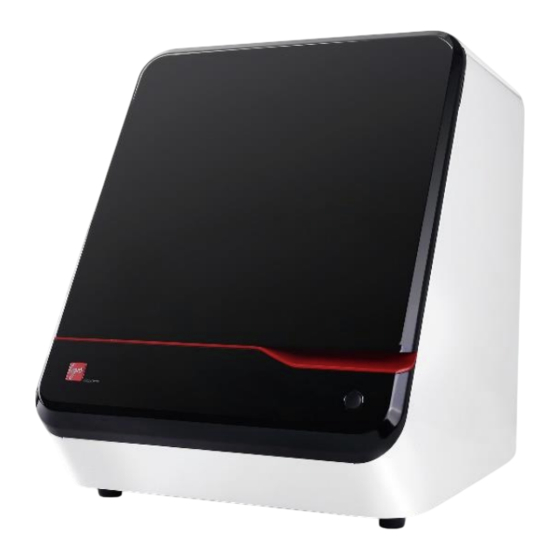
1.2 Product description CELENA® X High Content Imaging System Your CELENA® X High Content Imaging System is an integrated imaging system designed for rapid, high content image acquisition and analysis. Customizable imaging protocols, image- based and laser autofocusing modules, and a motorized XYZ stage simplify well plate imaging and slide scanning. -
Page 7: Setting Up
1.3 Setting up Unpacking Move the unpacked boxes to the site of operation. CELENA® X CAUTION! When moving the CELENA® X, do not attempt to lift or move the instrument without assistance. It is recommended that two or more people lift the instrument together while taking the proper safety measures to avoid injury. -
Page 8: Shipping Guard/Restraints
Shipping guard/restraints Your CELENA® X is shipped with two shipping restraints installed (X/Y stage, LED filter cube stage) to prevent damage to the instrument from shock and vibration during transport. IMPORTANT! The shipping restraints must be removed before the CELENA® X is turned on. Remove shipping restraints Unscrew screw A and pull it up to remove it from the LED filter cube stage cover. -
Page 9: Celena® X Explorer
2. CELENA® X Explorer 2.1 User interface The CELENA® X Explorer is the graphical user interface for the CELENA® X High Content Imaging System. CELENA® X Explorer ① CHANNELS: Gives control over light, camera, and focus settings. ② VESSEL: Allows you to select the appropriate vessel, wells, and fields to capture. ③... -
Page 10: Channels
Channels This panel is used to set light, camera, and focus parameters for a project. ① Add: Adds the CHANNELS settings to the project protocol. ② Objectives: Allows you to select from the currently installed objectives. ③ Channels: Allows you to select from the currently installed filter cubes and adjust light and camera settings. - Page 11 IMPORTANT! Minimize the time that the sample is being exposed to light to prevent photobleaching and/or phototoxicity. ② Condenser: Is installed at the time of purchase (BF: brightfield, PH: phase condenser). Click the condenser (BF or PH) button for transmitted light. The dropdown menu allows you to control the condenser’s iris diaphragm.
- Page 12 Note: The speed of the image-based autofocus is entirely dependent on the set exposure. Reducing the exposure will increase focusing speed. Multiscan AF Multiscan AF is used to set up autofocusing for demanding batch image acquisitions such as multi-well plate imaging, slide scanning, and time-lapse imaging. Prior to setting up Multiscan AF, make sure to bring the current field into sharp focus.
-
Page 13: Vessel
② Image AF: Select to set up image-based autofocusing. Make sure the current field is focused sharply. Autofocus range: Use to set the range to scan from the current focal position. Focus offset: Choose to turn the focus offset on or off. The CELENA® X will calculate the difference between what the system defines as the optimal focal plane and what you define as the focal plane of interest and automatically calibrate the focus accordingly. -
Page 14: Z-Stack
Z-stack This panel allows you to set up Z-stack imaging. These settings apply to each added channel. ① Add: Adds the Z-STACK settings to the project protocol. ② Method: Allows you to select from three Z-stack imaging methods. ③ Z-stack settings: Allows you to set the Z-stack imaging parameters. There are three methods of operation: Start/End Start... -
Page 15: Time Lapse
Time lapse This panel allows you to set up time lapse imaging for the project protocol. This applies to each channel. Selected fields are captured at set intervals over an allotted period of time. ① Add: Adds the TIME LAPSE settings to the project protocol. ②... -
Page 16: Project
Project The project control panel is used to: Create and run a project Open or save a project protocol ① Create project: Allows you to start a project to image. This creates a project folder where all generated data will be stored. ... -
Page 17: Toolbar
④ Save protocol as: Allows you to save a protocol. This saves a protocol file (.cxprotocol) for future use. ⑤ Protocol details: Shows you the protocol details. Toolbar The toolbar has tools for capturing and visualizing the current field of view. Capture Save Pseudocolor... -
Page 18: Settings
Settings Settings allows you to set system options and perform calibration procedures. To access the Settings window, click the Settings wheel above the tool bar. Camera The camera settings allows you to select the camera, bit depth, saturated pixel color, as well as auto white balance the color camera. - Page 19 Vessels The vessels settings allows you to create and edit custom vessels. ① Vessel details: Can be used to select the vessel type, number of wells, well shape, and vessel name. ② Vessel description: Shows the associated catalog numbers of the selected vessel. ③...
-
Page 20: Workflow
2.2 Workflow Create a project protocol Overview Upon starting Explorer, you will create a new project protocol to capture images. Select vessel. ▼ Select objective. ▼ Select a channel. ▼ Set light and camera parameters. ▼ Focus on the sample. ▼... - Page 21 For fluorescence imaging, click the desired fluorescence channel to select the corresponding light source. If the channel you need is not available, go to Settings > Filter cubes to install a different filter cube. Tips: When searching for a sample, increase gain and decrease exposure for a faster frame rate.
-
Page 22: Save A Project Protocol
Range (current): Move the to the desired start position. To set the imaging range, enter how far above (+) and below (-) the current position to set the imaging range. Select to capture images at specific intervals (µm) or to capture a specific amount of images (steps) and enter the desired value. -
Page 23: Celena® X Cell Analyzer
3. CELENA® X Cell Analyzer 3.1 Overview CELENA® X Cell Analyzer can be used to set up automated image analysis sequences to batch process images captured on the CELENA® X. Cell Analyzer also provides tools to edit and annotate images as well as create videos. The CELENA® X Cell Analyzer Verification Key must be plugged into use Cell Analyzer. -
Page 24: View
View This panel allows you to view the captured images and select wells to analyze. Figure 1 VIEW panel\\\\\\\\\\\\\\\\\\\\\\\\ ① Channel: Allows you to select which channels to display. ② Well: Allows you to select which well to view. ③ Field: Allows you to select the field in the selected well to view. -
Page 25: Image Control
Image control This panel allows you to edit images, add annotations, and make simple measurements. ① Annotation tools: Allows you to mark and measure specific areas of interest. ② Show markups: Shows or hides annotations. ③ Editing tools: Allows you to adjust the brightness and contrast of each channel ④... -
Page 26: Analysis
Analysis This panel allows you to set up, edit, and run analysis pipelines. ① Open analyzed results: Allows you open a previously analyzed project (.cxasis). ② Analysis name: Shows you the analysis name. ③ Pipeline modules: Shows you the modules in the pipeline. ④... -
Page 27: Messages
Messages This panel is used to display system messages, annotation measurement data, module details, and analysis results. You can resize the message panel by dragging the top border. There are four tabs: Messages, Data, Modules, and Results. Upon analysis, additional tabs will appear for each analyzed object. -
Page 28: Workflow
3.2 Workflow Set up project analysis Overview Using Cell Analyzer, users can create an image analysis pipeline, which is a sequence of modules that each perform a specific image processing task. This allows the quantitative analysis of multiple cellular features from images. Modules can be mixed, matched, and adjusted to measure phenotypes of interest quantitatively. -
Page 29: Load Previously Analyzed Images
Create a pipeline Click ADD MODULE in the ANALYSIS panel. Select the module(s) you want to use from the modules box and click Add to Pipeline. When finished, click Close. Modules are processed in the order specified. Adjust the sequence by dragging and dropping modules or by using the ▲... -
Page 30: Edit Images
4. Export (Optional) To export measurement data, select the desired measurement(s), right-click, and click Export CSV. (Optional) To save the annotated image, click the export images icon in the toolbar. Edit images 1. Open project Make sure the project folder created by CELENA® Explorer is on your computer. Click the folder icon next to Project path. -
Page 31: Pipeline Module Reference
3.3 Pipeline module reference Overview Pipeline modules can be divided into the following categories: 1) Image processing ColorToGray EnhanceEdges EnhanceOrSuppressFeatures FilterObjects GrayToColor ImageMathOverlay Invert MaskImage OverlayOutlines Smooth 2) Object identification IdentifyPrimaryObject IdentifySecondaryObject IdentifyTertiaryObject 3) Measurements MeasureImageAreaOccupied MeasureObjectIntensity MeasureObjectSizeShape Image processing ColorToGray The ColorToGray module converts RGB color images to grayscale images. - Page 32 EnhanceOrSuppressFeatures The EnhanceOrSuppressFeatures module enhances or suppress specific features in an image to improve downstream object identification. Module settings: Select the input channel. Name the output image. Select to: Enhance or Suppress features. If 3a, select a feature type to enhance. Choose from the following: Speckles Neurites Dark holes...
- Page 33 Generated measurements: Count: The number of objects remaining after filtering. Parent: The identity of the input object associated with each filtered (remaining) object. Location_Center_X: The X coordinate of the center of mass of the filtered object. Location_Center_Y: The Y coordinate of the center of mass of the filtered object.
-
Page 34: Object Identification
Object identification Pipelines will depend on identifying the objects in the image. In Cell Analyzer, you will identify primary, secondary, or tertiary objects. IdentifyPrimaryObject The IdentifyPrimaryObject module identifies primary objects from grayscale images. A primary object is an object that can be identified in an image without needing another object or image as a reference. - Page 35 Tips: Images must be grayscale. The regions of interest must be lighter than the background – if they are dark on a light background, invert the images using the Invert module upstream. Primary objects must be completely contained within a secondary object. Secondary objects must be larger than or equal in size to primary objects.
-
Page 36: Measurements
Measurements MeasureImageAreaOccupied The MeasureImageAreaOccupied module measures the total area occupied by identified objects within an image. Module settings Select objects to measure. Generated measurements: AreaOccupied: The total area occupied by the input objects. MeasureObjectIntensity The MeasureObjectIntensity module measures the intensity of identified objects. Module settings: Select a channel. - Page 37 Eccentricity: The eccentricity of the ellipse that has the same second-moments as the region. The eccentricity is the ratio of the distance between the foci of the ellipse and its major axis length. The value is between 0 and 1. (0 and 1 are degenerate cases;...
-
Page 38: Maintenance
If liquid is spilled on the instrument, turn off the power and wipe dry immediately. Use only optical-grade cleaning materials to clean optical components. Do not exchange components between instruments unless they have been provided or authorized by Logos Biosystems. 4.2 Change filter cubes Procedure Go to Settings >... -
Page 39: Change Objectives
Gently pull out the filter cube. Insert the desired LED filter cube, fasten the screw, and plug in its connector. Repeat as necessary. Click Finish when complete. This will return you to the original filter cubes settings window. Select the installed filter cube from the registered filter cubes list. Select the post in which it was installed from the installed filter cubes list and click >>. -
Page 40: Adjust Objective Correction Collars
Click Finish when complete. This will return you to the original objectives settings window. Select the installed objective from the compatible objectives list. Select the post in which it was installed from the installed objectives list and click >>. Double-click the label box to change how it shows up in the CHANNELS panel. Use the DEL, ▲, and ▼... -
Page 41: Appendix A: Troubleshooting
Appendix A: Troubleshooting Image quality Uneven focus Make sure the vessel bottom is clean and free of fingerprints. Place the vessel in the appropriate vessel holder. Make sure it fits snugly and lies flat. Make sure you focus sharply on a sample before setting up the autofocus for Multiscan AF. Make sure you have selected the correct vessel. -
Page 42: Appendix B: Specifications
Pass, Cy5 Long Pass, custom filters Objective turret Motorized; 5 interchangeable objectives Compatible objectives 1.25-100X; Olympus, Zeiss, and Logos Biosystems objectives Condenser Motorized; basic or phase contrast condenser Basic: 60 mm LWD condenser, 4-positions Phase contrast: 60 mm LWD condenser, 4-positions with 3 phase annuli... -
Page 43: Appendix C: Safety Information
Do not touch the instrument or its components with wet hands. Use components provided or authorized by Logos Biosystems. If the proper combination of components is not used, product safety cannot be guaranteed. Use only the provided power cord and AC adapter. If the proper components are not used, electrical safety of the product cannot be guaranteed. -
Page 44: Personal Safety
Community provisions for which this marking is required. Users must be aware of and follow the conditions described in this manual for operating the instrument. The protection provided by the instrument may be impaired if the instrument is used in a manner not specified by Logos Biosystems. Korean standards Symbol Description The KC certification mark indicates that this instrument conforms with Korea’s... -
Page 45: Appendix D: Ordering Information
0.04 I10047 PLAPON 2X 0.08 I10050 UPLSAPO 60XO 1.35 0.15 0.17 I10051 UPLSAPO 100XO 0.13 0.17 Logos Biosystems Plan fluorite Cat # Objective WD (mm) Correction (mm) I10005 TC PlanFluor 4X 0.13 17.5 I10006 TC PlanFluor 10X I10007 TC PlanFluor 20X... -
Page 46: Led Filter Cubes
LED filter cubes Cat # Filter cube Excitation (nm) Emission (nm) I10130 DAPI 375/28 460/50 I10131 EGFP 470/30 530/50 I10132 530/40 605/55 I10133 mCherry 580/25 645/75 I10134 ECFP 436/20 480/40 I10135 EYFP 500/20 535/30 I10136 DSRed 530/40 620/60 I10137 620/60 700/75 I10138 710/75... -
Page 47: Appendix E: Purchaser Notification
Logos Biosystems, Inc. (“Company”) will not claim any consideration against the purchaser of infringement of patents owned or controlled by the Company which cover the product based on the manufacture, use or sale of... -
Page 48: Instrument Warranty
Instrument warranty Warranty Logos Biosystems, Inc. (“Company”) warrants to the original purchaser (“Purchaser”) that the instrument (“Instrument”), if properly used and installed, will be free from defects in materials and workmanship and will conform to the product specifications for a period of one (1) year (“Warranty Period”) from the date of purchase. - Page 49 Logos Biosystems HEADQUARTERS FL 2 & 3 28 Simindaero 327beon-gil, Dongan-gu Anyang-si, Gyeonggi-do 14055 OUTH OREA Tel: +82 31 478 4185 Fax: +82 31 360 4277 Email: info@logosbio.com 7700 Little River Turnpike STE 207 Annandale, VA 22003 Tel: +1 703 622 4660...
Need help?
Do you have a question about the Celena X and is the answer not in the manual?
Questions and answers