Table of Contents
Advertisement
Quick Links
Advertisement
Table of Contents

Subscribe to Our Youtube Channel
Summary of Contents for PROXALERT R5
- Page 1 Pilot’s Guide PROXALERT R5 Aircraft Proximity Alerter Version 1.4...
- Page 2 Proxalert Inc. Copyright © 2004 Proxalert Inc Document NUMBER PX-UM-R5-US-2004-05-12 - Version 1.4...
- Page 3 Your will need to be in your aircraft to check the cruise altitude alerter and local transponder. For the first flight with your R5 unit we recommend you fly with a fellow pilot so you will have time to explore the versatility of your R5 unit. You don’t have to constantly monitor the R5 unit LCD panel when airborne.
-
Page 4: Table Of Contents
Brief description............................................9 An aircraft proximity alerter ......................................... 9 A cruise altitude alerter .......................................... 9 A local transponder tester ........................................9 Unpacking your R5 unit ..........................................10 The R5 user’s interface..........................................11 Front panel ............................................11 Back panel ............................................. 12 Menu structure............................................ - Page 5 Setting up your R5 unit..........................................20 Placement .............................................. 20 Electrical wiring............................................ 21 Power Supply............................................22 External aircraft power........................................22 External battery pack........................................22 External power brick........................................22 Antenna............................................... 23 Direct mount (standard configuration) .................................... 23 Remote mount..........................................24 External antenna..........................................24 Audio ..............................................
- Page 6 Operating your Local Transponder Tester ....................................38 Principle of operation ........................................... 38 Limitations ............................................39 Code corresponding to an altitude....................................... 39 Optimal distance between R5 antenna and transponder antenna ............................39 Proximity and altitude alerter off during operation ................................39 Maintenance .............................................. 40...
- Page 7 Firmware upgrade procedure ......................................40 Permanent installation..........................................41 Mechanical ............................................41 Antenna ..............................................41 Power ..............................................41 Audio..............................................41 Appendix A..............................................42 Specification ............................................42 Appendix B..............................................43 Proxalert Customer Service ......................................... 43 Appendix C..............................................44 Electromagnetic compatibility (EMC) approvals................................44...
-
Page 8: Important Information
As with all technology, this unit has certain limitations you should be aware of if you are to get the best results. Cautions and limitation The Proxalert R5 may not detect all aircraft flying in the detection volume. The purpose of this unit is to provide you with additional information to help you make visual contact with threat aircraft. -
Page 9: Brief Description
The R5 collision avoidance system detects transponder replies from aircraft flying in your vicinity and simultaneously displays squawk code, altitude and estimated distance of up to three traffic threats. The R5 is a passive device so you need to be under radar coverage. Once a threat is identified, a vertical trend symbol will inform you if the threat aircraft is climbing, descending or leveling. -
Page 10: Unpacking Your R5 Unit
Unpacking your R5 unit Your R5 kit contains the following items. Before preparing your unit for use, please check that all these parts are included. Contact your Proxalert representative for part replacement. Description Quantity À The R5 unit Á Cigarette lighter plug cable Â... -
Page 11: The R5 User's Interface
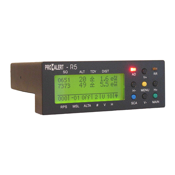
The R5 user’s interface Front panel The front panel includes a back lighted LCD display, two LEDS (red and orange), four range setting pushbuttons arranged in a cross pattern and three colored function pushbuttons. LCD display fields Pushbuttons Threat squawk code... -
Page 12: Back Panel
Back panel The back panel includes four connectors. Each connector type is different so there is no risk of misconnecting cables during set-up. Name Type Function Direction Cable to use AUDIO cable ± AUDIO OUT Jack ¼” female socket Audio Low level output Z=100 ohms Output SERIAL PORT Cannon™... -
Page 13: Menu Structure
Menu structure To enter the Main menu from the threat display screen press the MENU pushbutton (Yellow). The Main menu is structured in two rows of four icons (submenu). The lower row icons are ‘connected’ to parameters or functions useful when not airborne. -
Page 14: Set Lcd Display
Set LCD display LCD display contrast varies with temperature and view angle. Adjust the contrast setting according to these parameters. Backlight operation increases power consumption. If you operate your unit from battery and during daylight we recommend switching the backlight to OFF position. Press MENU key to get to LIGHT submenu Press H+ increase contrast Press H- decrease contrast... -
Page 15: Set Display Mode
Set Display mode Your R5 offers different ways to display crucial threat information. A traffic threat may be ranked by altitude proximity or distance proximity. The top LCD line always displays the threat posing the highest collision hazard according to the ranked method you have selected. -
Page 16: Set Cruise Altitude Range
Set cruise altitude range Press MENU to get to CRUISE ALTITUDE ALERTER submenu Press H+ to increase Range Press H- to decrease Range Press MENU to return to MENU main panel... -
Page 17: Set Audio Modes
Set audio modes Press MENU to get to AUDIO MODE submenu Press H+ to set Proximity alarm to On Press H- to set Proximity alarm to Off Press MENU to return to MENU main panel Press H+ to set Altitude alerter alarm to On Press H- to set Altitude alerter alarm to Off Press MENU to return to MENU main panel Press H+ to set System alarm to On... -
Page 18: Start Firmware Upgrade
Start firmware upgrade Press MENU to get to the UPGRADE FIRMWARE submenu Press H+ to start the firmware upgrade Press MENU to return to MENU main panel If you return to the MENU main panel the unit firmware will not be erased or damaged. The unit is ready to upgrade waiting for communication with the host personal computer. -
Page 19: Display Calibration Information
Display Calibration information Press MENU to get to CALIBRATION submenu Press MENU to return to MENU main panel Exit Press MENU to leave MENU panel The unit is now back to normal operation... -
Page 20: Setting Up Your R5 Unit
The volume of metal included in your R5 unit has been minimized to avoid interference with your magnetic compass. Locate your unit at least at 2” from your magnetic compass. The same rule must be applied to the R5 power cable as electrical current creates a magnetic field that may also influence your compass indication. -
Page 21: Electrical Wiring
For proper operation, your R5 unit needs a power supply with the specified voltage in order to receive radar signals through its antenna. When installing the R5 in the cockpit, ensure that the cables do not compromise your ability to control your aircraft. The R5 unit features an internal re-set fuse and a 1 Amp fuse integrated in the power cable included in your kit. -
Page 22: Power Supply
E x t e r n a l b a t t e r y p a c k Your R5 unit may operate from an external battery pack provided the voltage is within limits (6 to 16 volts). The usage time will vary depending on the battery technology. -
Page 23: Antenna
D i r e c t m o u n t ( s t a n d a r d c o n f i g u r a t i o n ) Connect the antenna provided in your R5 kit as shown on the picture below. Be sure to install the antenna in a vertical position. Radar replies are vertically polarized electromagnetic waves. -
Page 24: Remote Mount
R e m o t e m o u n t In some cockpit configurations it may be necessary or desirable to install the R5 unit in a side pocket (glider) or in a position where the antenna can’t be directly connected and/or maintained in vertical position. -
Page 25: Audio
Q u i e t c a b i n If you operate your R5 in a quiet cabin environment (i.e. glider) and are not wearing a headset, you will hear audio alerts through the R5 internal speaker N o i s y e n v i r o n m e n t In all other cases you will need to connect the AUDIO OUT port to your headset using the accessories included in your R5 kit. -
Page 26: Operating Your Aircraft Proximity Alerter
The R5 unit detects traffic provided it is equipped with a mode A or mode C in the ‘ON’ or ‘ALT’ position. Threat traffic altitude will be reported in 100 ft The figure below illustrates the different setting parameters and their functional limits. -
Page 27: Horizontal Range Setting
Horizontal range setting The horizontal range is simply set by pressing the H+ pushbutton to increase or H- to decrease. The R5 must be set according to your flight profile: To display code and altitude reported by your local transponder. (See ‘Local transponder tester’ section) 1 Nm For very congested area. -
Page 28: Threat Squawk Code
Out of the 4,096 available combinations, historically some have been used to carry altitude information. Due to increasing traffic, the ATC now uses these reserved codes to carry code. Your R5 unit implements a proprietary algorithm to display the proper code in most cases. A ‘!’ symbol displayed next to the code will indicate that the threat code is actually an altitude. -
Page 29: Threat Altitude Reporting
Mode A only transponder If the traffic threat is equipped with an old mode A transponder, or if the transponder is a mode A/C not set to ‘ALT’, your R5 will still detect this threat. It will display three dashes since altitude is not available. -
Page 30: Limitations
M u l t i p l e t h r e a t s w i t h s a m e s q u a w k c o d e Non-controlled VFR flights use a dedicated code: 1200 in the USA and 7000 in Europe. If your R5 unit detects more than one traffic threat squawking the same code it will display this code once (on one line). -
Page 31: Vertical Trend Indicator
Principle of evaluation The R5 unit permanently monitors traffic threat altitudes and memorizes them every eight seconds if available. By comparing consecutive altitude samples, the unit will evaluate the vertical trend provided these samples are coherent and come from the same aircraft. -
Page 32: Estimated Distance (Enm)
The R5 unit is a passive device. It monitors threat radar replies by measuring the signal amplitude of threat radar replies and simultaneously evaluating the distance to threat. -
Page 33: Limitation
What could be seen as a drawback is in fact an advantage since it allows your R5 unit to have more time to detect a traffic threat flying at a significantly higher speed than light general aviation aircraft. -
Page 34: Traffic Alerts
Audio alert The R5 unit sends an audio alert if a new threat is detected in range. The audio alert consists of a sequence of four tones grouped by two (di di …di di). This sequence may be heard simultaneously with an Air Traffic Controller message and it will not affect the clarity of the Air Traffic Controller message. -
Page 35: Operating Your Cruise Altitude Alerter
Principle of operation Your R5 unit features a simple yet effective cruise altitude alerter. The unit monitors your altitude based on information provided by the built-in pressure sensor. Altitude tolerance range is the only parameter to set before each use. The following figure shows how the altitude tolerance range is defined. -
Page 36: In Flight Usage
In flight usage Once the altitude tolerance range has been set, your cruise altitude alerter is fully controlled by a single pushbutton: The blue key. Upon reaching your cruise altitude Press once the pushbutton to memorize your altitude (Flight level). The LCD panel ALTA field displays your memorized altitude for three seconds then the signed altitude difference between your memorized and actual altitude. -
Page 37: Limitations
The R5 unit’s built-in altimeter must not be used as a reference for vertical navigation. The built-in altimeter resolution varies with altitude. A properly calibrated R5 will exhibit a typical accuracy of ± 150 feet. If during a flight the difference is larger, the R5 probably needs a fresh altimeter calibration. -
Page 38: Operating Your Local Transponder Tester
Principle of operation Your R5 unit receives radar replies both from traffic threats as well as from your local transponder. During normal operation the R5 will not consider your local transponder as a threat to avoid issuing a constant alert. To display your local transponder information you need to reduce the horizontal range until an X is displayed on the LCD panel H field. -
Page 39: Limitations
Optimal distance between R5 antenna and transponder antenna Your local transponder antenna must be located at a significant distance from the R5 unit antenna to avoid saturation of the radar receiver. If no information appears on the LCD panel your unit is probably saturated or you are not under radar coverage. -
Page 40: Maintenance
Your unit requires no special maintenance operation unless a distance calibration is required. (See Calibration section) From time to time Proxalert will publish a new version of the R5 firmware to enhance operational performance. As a user you are responsible to keep your R5 unit up to the latest firmware level. -
Page 41: Permanent Installation
→ Always use 50 or 52 ohms coaxial cable and preferably RG-400 or RG-142 cable. Limit the cable length to 10 feet. → Do not use the antenna included in your R5 kit for outdoor usage. A transponder or DME style blade antenna may be used in this case. -
Page 42: Specification
1 watt typical without backlight 1.5 Consumption Output impedance watt typical with backlight Internal speaker for quiet cabin or ground usage Mode Mono or stereo thru proprietary cable Note: The ProXalert R5 operates as an EFB Class 1 device. (EFB: Electronic Flight Bag) -
Page 43: Proxalert Customer Service
Your unit must be returned to the place where you purchased your unit. To avoid misalignment or damages your unit has been sealed at factory. Any attempt to open your unit case will void your warranty. There are no owner-serviceable parts inside your R5 unit. -
Page 44: Electromagnetic Compatibility (Emc) Approvals
Appendix C Electromagnetic compatibility (EMC) approvals U n i t e d S t a t e s o f A m e r i c a ( F C C ) This device complies with Part 15 of the FCC limits for Class B digital devices. Operation is subject to the following two conditions: (1) This device may not cause harmful interference, and (2) This device must accept any interference received, including interference that may cause undesired operation. - Page 45 E u r o p e a n E c o n o m i c C o m m u n i t y D e c l a r a t i o n o f C o n f o r m i t y According to ISO/IEC Guide 22 and EN 45014 Manufacturer’s name: Proxalert, Inc. Manufacturer’s Address: 3420 East Shea Boulevard, Suite 188, Phoenix, AZ 85028 USA Declares that the product...
Need help?
Do you have a question about the R5 and is the answer not in the manual?
Questions and answers