
Related Manuals for Reer SV MR0

Summary of Contents for Reer SV MR0
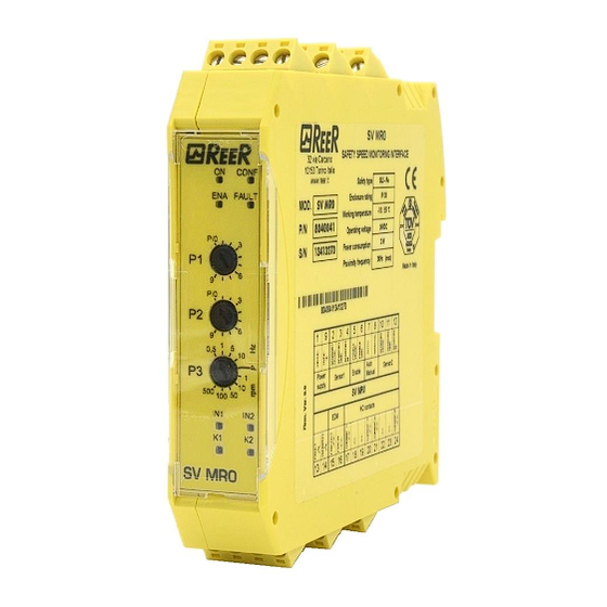
- Page 1 Installation Instructions Safety Speed Monitor SV MR0 8540963 - 25/03/2019 - Rev.8...
-
Page 2: Table Of Contents
Terminals ......................8 Set up of the device ..................... 9 Automatic/Manual mode selections ..............13 Enable input: ....................16 Technical data SV MR0 ..........................17 ..................18 Faults (blinkings) .................... 18 Additional notes ....................19 Pulse inputs, pulse pick-ups ................19 Switching outputs: .................. -
Page 3: Preliminary Note
SAFETY SPEED MONITOR SV MR0 PRELIMINARY NOTE The instructions are part of the unit. They are intended for authorised persons according to the EMC and Low Voltage Directive and safety regulations. The instructions contain information about the correct handling of the product. Read the instructions before use to familiarise yourself with operating conditions, installation and operation. -
Page 4: Safety Instructions
SAFETY SPEED MONITOR SV MR0 Safety instructions Follow the operating instructions. Improper use may result in malfunctions of the unit. This can lead to personal injury and/or damage to property during operation of the machine. For this reason note all remarks on installation and handling given in these instructions. -
Page 5: Operation
SAFETY SPEED MONITOR SV MR0 Operation GENERAL FUNCTION DESCRIPTION The speed monitor is a two-channel pulse evaluation system for safe overspeed detection. To do so, it receives the pulse sequences from the pulse pick-ups connected to the inputs. The module calculate the resulting frequency. -
Page 6: Hysteresis
Foh (in this case 950 rpm) (falling frequency) as in the drawing in "Switching function: overspeed". INITIALISATION Directly after power on, the SV MR0 carries out an initialisation comprising a complete self-test. After approx. 3 s the SV MR0 is ready for operation. -
Page 7: Installation
SAFETY SPEED MONITOR SV MR0 INSTALLATION Mechanical installation of the device Mount the device on a DIN rail in a housing protected against dust and humidity (min. IP 54). Leave enough space between the unit and the top and bottom of the housing to enable air circulation and to avoid excessive heating. -
Page 8: Electrical Connections
SAFETY SPEED MONITOR SV MR0 Electrical Connections Voltage supply +24VDC: max. 70mA, protected (by a resettable fuse at T=20 °C), short-circuit sensors: proof, not monitored. Ground: directly connected to the device ground. Sensors: PNP sensors, bounce-free. Feedback circuit: Yes - Max. 100 mA, short-circuit proof. - Page 9 SAFETY SPEED MONITOR SV MR0 Terminal connection: "UPPER SIDE" Operating voltage (+24VDC ) Sensor1 supply (+24VDC) Sensor1 supply (GND) Sensor1 input Operating voltage (GND) Sensor2 supply (+24VDC) Sensor2 supply (GND) Sensor2 input current path 1A (relay contacts) current path 1B (relay contacts) Terminal connection: "LOWER SIDE"...
-
Page 10: Set Up Of The Device
After the first power on of the device it is necessary to configure the Overspeed Frequency (Fo) using the three decade switches located in front of SV MR0. The switches allow the user to enter the value of the desired preset frequency (as described below). - Page 11 SAFETY SPEED MONITOR SV MR0 SWITCH OPERATION / RESULT Start of configuration: Set the 3 switches to configuration position 0/P Switch on the power supply of the device > The LED CONF is blinking Adjust Potentiometer P1 from the position 0/P to the needed Value >...
- Page 12 SAFETY SPEED MONITOR SV MR0 Examples The switch point value can only be set when operating voltage is connected to the device and the three switches are set as indicated (factory setting). Figure 1 Factory setting Set P1, P2 and P3 to obtain the switch point value. Examples:...
-
Page 13: Automatic/Manual Mode Selections
SAFETY SPEED MONITOR SV MR0 AUTOMATIC/MANUAL MODE SELECTIONS If overspeed is detected, the current relay paths open and the drive is switched off. This results that the input frequency falling again below the switch point and the current paths closing (below F... - Page 14 SAFETY SPEED MONITOR SV MR0 Figure 5 - Automatic mode selection Automatic mode In this operating mode, the relay outputs of the safety module check the value of the input frequency comparing it with the selected value: > With the input frequency below the selected value the relay outputs are active.
- Page 15 SAFETY SPEED MONITOR SV MR0 The RESTART command must be installed outside the danger area in a position where the danger area and the entire work area concerned are clearly visible. It must not be possible to reach the control from inside the danger area.
-
Page 16: Enable Input
SAFETY SPEED MONITOR SV MR0 ENABLE INPUT: If several modules with different switch points are used for overspeed monitoring of a drive, the devices whose switch point value is not relevant can be "switched off" by means of the enable input pairs. -
Page 17: Technical Data Sv Mr0
SAFETY SPEED MONITOR SV MR0 TECHNICAL DATA SV MR0 Voltage supply Supply voltage U 24VDC Voltage range 80 .. 120 % Power consumption < 3 W Device response time (ms) >100Hz) = 10,7 + 400*(f = selected frequency (by potentiometers) = input frequency (from proximities) <100Hz) -
Page 18: Faults (Blinkings)
SAFETY SPEED MONITOR SV MR0 DEFINITION OF THE LE COLOUR Input IN2 yellow Input IN1 Yellow Indicator Relay K2 Green Indicator Relay K1 Green Indicator Enable Yellow CONF Indicator Configuration Blue Power Indicator Green FAULT Fault Indicator Input Sensor IN2 lights, when a high signal at the input IN2 was detected. -
Page 19: Additional Notes
If the feedback function is not required, the terminals (15-16) can be permanently bridged. Checklist after installation Directly after power on, the SV MR0 carries out an initialisation comprising a complete self-test. Anyway to have the system perfect operation perform the following checks at start up and at least every one year: Verify that all the cables are correctly inserted and the terminal blocks well screwed. -
Page 20: Application Note
SAFETY SPEED MONITOR SV MR0 Application Note The module checks that the two input frequencies are the same (with the appropriate tolerances), regardless of their phase relationship. This means that in a mono-directional movement of the two speed sensors can be distributed in a free manner along the path of detection. - Page 21 SAFETY SPEED MONITOR SV MR0 In this case the two inputs will read two different frequencies and the module will go into Fault condition with four flashes of led EXT, IN1 and IN2. The solution in this case is to change the position of the proximity switch (or of the reference marks) so that the pulses can be detected from both proximities.
-
Page 22: Warranty
Precise, complete compliance with all the rules, instructions and prohibitions indicated in this handbook is an essential requirement for correct functioning of the safety interface. ReeR s.p.a. therefore declines any responsibility for all and anything resulting from failure to comply, even partially, with such indications.. - Page 23 SAFETY SPEED MONITOR SV MR0 8540963 - 25/03/2019 - Rev.8...
Need help?
Do you have a question about the SV MR0 and is the answer not in the manual?
Questions and answers