Advertisement
Quick Links
Mid-West
Instrument
MODEL 522
Installation and Operating Instructions
SYMBOLS USED ON PRODUCT
Caution Risk of Danger. Please refer to this
documentation when seen marked on the
product.
Equipment protected throughout by double
insulation.
This product is CE marked for conformance
with the Low Voltage Directive (73/23/EEC)
INSPECTION
Before installation check the receiving paperwork and
the intended application for correct part number,
materials of construction, working pressure, dial range,
etc. If equipped with switches, check electrical rating.
Inspect for shipping damage and, if damaged, report it
immediately.
NOTE - Before attempting repairs contact your
local Mid-West Representative or our factory.
Failure to do so will void any warranty.
INSTALLATION
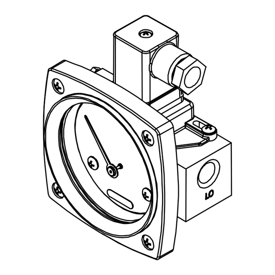
The model 522 Indicating Differential Pressure Gauge /
Switch is calibrated and tested prior to shipment and is
ready for immediate installation. Use of the following
installation procedures should eliminate potential
damage and provide optimum trouble-free operation.
1. PROCESS CONNECTIONS
1/4" FNPT are provided as standard but check
paperwork for connections ordered.
connections on the body identified as "hi" and "lo" for
high pressure and low pressure.
plumbed to the proper connections on your system.
Improper connection will not damage the instrument,
but it will not function properly.
2. INSTRUMENT LOCATION
On liquid service the instrument should be mounted
below the process connections to facilitate self-
bleeding. On gas service it should be located above
the process connections to promote self-draining. If
the process contains particulates, a "pigtail" loop or
drop leg (manometer "U-tube" configuration) in the
tubing will minimize the possibility of it migrating into
the instrument.
®
There are two
Be sure these get
MATERIALS:
Elastomers: As specified on the order
Body: As specified on the order
Internals: Acetal, Ceramic, & SS
Switch: Flame Retardant VALOX & Flame
Retardant Epoxy
Connector: Polyamide 6, 30% Glass Fill, Flame
Retardant
ELECTRICAL (LE OPTION)
WARNING: ELECTRICALCONNECTIONS
SHOULD BE PERFORMED BY
QUALIFIED PERSONNEL AND
MEET
REPRESENTATIVE
ELECTRICAL CODE.
IT IS RECOMMENDED
POWER TO THE SWITCH PRIOR TO
MAKING SET POINT ADJUSTMENTS.
CAUTION: THIS DEVICE DOES NOT REQUIRE
POWER TO OPERATE.
DIRECTLY ACROSS A MAINS POWER
SOURCE MAY DAMAGE THE SWITCH.
The SPST (Single Pole Single Throw) switch is
intended for on / off control or status input to devices
that have load characteristics within the ratings of 60
Watts max, 3 A max., 240 VAC / VDC maximum. The
product of the switching voltage and current shall
not exceed 60 W.
The adjustable switch supplied with your order can be
re-adjusted between 40% and 95% of the full scale
range of the gauge by loosening the two adjustment
screws and sliding the switch assembly. Sliding the
switch to the left (facing the dial front) decreases the
switch set point. Re-tighten the switch adjust locking
screws while applying light pressure to assembly to
keep it from rotating or shifting.
Interface:
The DIN interface conforms to DIN 43 650A / ISO 4400
and when mated provides an IP65 rated protection
class. The right angle mating connector is supplied
with the gauge upon order. Clocking (orientation) can
be changed by prying out the insert and rotating the
insert to the desired clocking (90 º increments).
Wiring to the SPST switch is between
terminals 1 & 2.
BULLETIN NO. IM522/11A
NATIONAL
TO REMOVE
CONNECTION
Advertisement

Related Manuals for Mid-West Instrument 522

Summary of Contents for Mid-West Instrument 522
- Page 1 / off control or status input to devices that have load characteristics within the ratings of 60 The model 522 Indicating Differential Pressure Gauge / Watts max, 3 A max., 240 VAC / VDC maximum. The Switch is calibrated and tested prior to shipment and is product of the switching voltage and current shall ready for immediate installation.
- Page 2 System (process) temperatures may exceed these limitations with proper installation. Contact our customer service representative for details. STANDARDS: All Model 522 Series differential pressure gauges either conform to and/or are designed to the requirements of the following standards: ASME B1.20.1 CSA-C22.2 No.
- Page 3 Mating Connector: Connection Instructions (Note: Delivered connector may appear different from item pictured) Remove the plug-in connector from the gauge assembly and using a screwdriver pry out the insert from the connector shell. Insert connection wires through the connector shell as shown. Strip wire lead ends and connect to terminal locations 1 &...
- Page 4 Standard Model Specifications: 522-AA-02-OO 1000 PSIG Working Pressure, Aluminum body, 316L Stainless Steel, Ceramic & Acetal Internal Parts Buna-N Diaphragm and Seals, ¼” FNPT End Connections 2-1/2” Round Black on White Dial w/ Engineered Plastic Case & Shatter Resistant Acrylic Lens Accuracy ±5% Full Scale(Ascending)
Need help?
Do you have a question about the 522 and is the answer not in the manual?
Questions and answers