
Subscribe to Our Youtube Channel
Summary of Contents for Lorrca MaxSis
- Page 1 LORRCA MAXSIS USER MANUAL Version 5.04 MRN-231-EN Master Registration Number: MRN-231-EN...
- Page 3 Manufacturer: RR Mechatronics Manufacturing B.V. Phone: +31 229 291 129 Fax: +31 229 241 534 E-mail: support@rrmechatronics.com Internet: http://www.rrmechatronics.com P.O. Box 225 Postal address: 1620 AE Hoorn The Netherlands De Corantijn 13 Office address: 1689 AN Zwaag The Netherlands © Copyright RR Mechatronics Manufacturing B.V. All rights reserved.
- Page 5 Introduction of 5.03 January 2019 Installation H. Schavemaker Oxygenscan option Program Operational instructions Introduction 5.02 October 2017 Installation H. Schavemaker Software version Program 5.xx Lorrca 1.01 Lorrca Maxsis User Manual Page 3 Version 5.04 MRN-231-EN...
-
Page 7: Table Of Contents
Features of the Lorrca® MaxSis ..............21 3.3.3. Symbols ......................22 3.3.4. General measurements description .............. 24 3.3.4.1. Principle of operation Lorrca® MaxSis ............. 24 3.3.4.2. Introduction Osmoscan ................26 3.3.4.3. Introduction RBC-elongation ..............26 3.3.4.4. Introduction RBC-aggregation ..............26 3.3.4.5. Introduction Oxygenscan ................27 ... - Page 8 Contents 5.5. Checking Lorrca® MaxSis functionality ..............47 5.5.1. Instrument status ..................48 5.5.2. Lorrca IO ....................... 49 5.5.3. Camera ......................50 6. LORRCA MAXSIS PROGRAM ..................51 6.1. Main screen ......................52 6.2. Main screen settings ....................52 6.2.1. ...
- Page 9 Insert blood sample membrane screen ............124 7.6.3. Adjust video camera membrane screen ............. 126 7.6.4. Cell membrane stability results screen ............127 7.6.5. Deformability results 2 screen ..............128 7.6.6. Start new measurement ................128 Lorrca Maxsis User Manual Page 7 Version 5.04 MRN-231-EN...
- Page 10 Oxygen sensor spot protocol ................160 10.4. Replacement sensor-spot .................. 161 10.5. Visual checks ..................... 163 10.6. Lorrca reagents routine ..................163 10.7. Adjusting geometry parameters ................. 164 10.8. Back up the results file ..................164 10.9. Update the software ................... 164 ...
- Page 11 11.6.2.2. RBC-aggregation and –relaxation measurements ....... 205 11.6.2.3. Flow to Stasis Aggregation Ratio (FSAR) ..........212 11.6.3. References ....................215 12. DRAWINGS AND PARTS LORRCA® MAXSIS ............219 12.1. LORC070020 Tubing diagram ................219 12.2. LORC080020 Connection diagram ..............220 ...
-
Page 13: About Rr Mechatronics
The unique collaboration between the scientific world and our research & development department enabled us to develop the Lorrca® MaxSis. This also makes it our responsibility to link and disseminate the knowledge gained in the worldwide community of researchers and clinicians. -
Page 14: Introduction
Read the whole Manual through carefully, especially chapter Safety (on page 28), before using the instrument. The section LoRRca MaxSis Program (on page 51) is interactive and most of the software functions are the same as in the program itself. -
Page 15: Typographical Conventions
Input parameters like Current Density, Scan Speed Names of the keys on [ALT]+[PRINT SCREEN] the keyboard like Specific warning text is shown as: Warning: Do not open during operation Lorrca Maxsis User Manual Page 13 Version 5.04 MRN-231-EN... -
Page 16: Used Symbols
Information sign on the supplied materials intended to inform about the “USE BY” date. This symbol indicates useful tips and other important information, that are not related to any specific danger. This symbol indicates a reference to this or other product documentation. Page 14 Lorrca Maxsis User Manual Version 5.04 MRN-231-EN... -
Page 17: Instrument Description
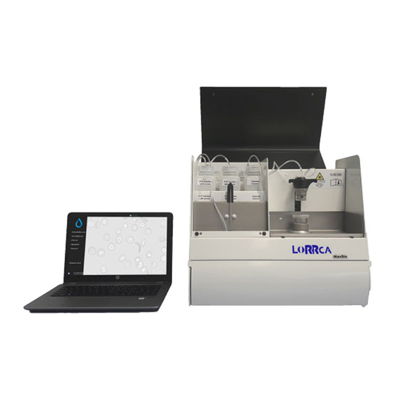
Instrument description 3. INSTRUMENT DESCRIPTION The Lorrca® MaxSis consists of the instrument and a control PC with printer. You can find detailed drawings of the main components in LORC109000 Desk arrangement. Main components: 1. Computer and display 2. BOB 3. CUP 4. -
Page 18: Instrument Label Lorrca® Maxsis
Instrument description 3.1. Instrument label Lorrca® MaxSis The CE marking and other important information can be found on the Mechatronics instrument identification plate, an illustration of this is shown below with explanation. The instrument identification plate is located on the right-hand side of the rear panel of the instrument under the main switch panel. -
Page 19: Technical Specifications
Instrument description 3.2. Technical specifications Technical specifications for the Lorrca® MaxSis: Lorrca® instrument models: Model name Catalogue number Model Lorrca® MaxSis LORC109003 100/240V 50-60Hz Mains voltage Slow blow 220V 1.6 Amp Fuse (20 x 5 mm) Slow blow 110V 3.15 Amp... - Page 20 Heating accuracy ± 0.2 °C Heater Range 25 - 45 °C Tech specs Gradient assembly mixer range 0 - 25 mS/cm Gradient mixer accuracy ±-0.5 mS/cm Reagents 50 - 500 mosm/kg Page 18 Lorrca Maxsis User Manual Version 5.04 MRN-231-EN...
- Page 21 Instrument description Duration maximum 10 minutes Dilution (with full blood) < 200:1 ± 20% <5% at 3Pa VC elongation measurement Lorrca Maxsis User Manual Page 19 Version 5.04 MRN-231-EN...
-
Page 22: Introduction Lorrca® Maxsis
Until otherwise labelled, the Lorrca® MaxSis is NOT released by the manufacturer as an in-vitro diagnostic medical device (IVD). Until otherwise published, the Lorrca® MaxSis is NOT validated by the manufacturer for any diagnostic or therapeutic purposes. The manufacturer does not accept liability for any consequences arising from the use of the Lorrca®... -
Page 23: Features Of The Lorrca® Maxsis
Instrument description 3.3.2. Features of the Lorrca® MaxSis Only 25 l blood needed for each deformability measurement. Easy sample changing. 3 mW laser-diode in shielded setup for maximum user safety. Adjustable shear rates from 0 - 800 s-1. -
Page 24: Symbols
Error of fit (au), average distance of the edge pixels to the best-fit ellipse. Aggregation parameters Isc dis Back-scatter intensity during disaggregation phase (au). Upstroke Height of syllectogram upstroke (au). Isc top Back-scatter intensity of syllectogram peak (au). Page 22 Lorrca Maxsis User Manual Version 5.04 MRN-231-EN... - Page 25 Shear rate (1/s at dIsc min. Textual <…> Text between < > refers to program buttons or to menu items. Not a Number (when, e.g., a parameter cannot be calculated) Red Blood Cell Lorrca Maxsis User Manual Page 23 Version 5.04 MRN-231-EN...
-
Page 26: General Measurements Description
Red Blood Cell (RBC) properties. The LoRRca MaxSis is therefore an indispensable instrument. It uses a Couette geometry with a static BOB and a rotating cylinder (CUP) to create a simple shear flow. - Page 27 The uni-exponential model is interesting to study, e.g., RBC-shape recovery in buffer solution The conventional bi-exponential model describes the aggregation process while the tri- exponential model includes both RBC-shape recovery and aggregation Lorrca Maxsis User Manual Page 25 Version 5.04 MRN-231-EN...
-
Page 28: Introduction Osmoscan
Instrument description 3.3.4.2. Introduction Osmoscan The Lorrca® MaxSis has an optional equipment with the possibility for automatic measurement of Red Blood Cell (RBC) deformability (expressed as elongation index, EI) as a continuous function of suspending medium osmolality. Both the shape and the position along the osmolality axis of specific features of these, so called osmoscans provide information about the cell`s deformability (at the chosen shear stress) as well as their intracellular viscosity and surface-volume ratio. -
Page 29: Introduction Oxygenscan
RBC behaviour directly reflects the status of the patients’ susceptibility to oxygen depletion. The Oxygenscan measurement represents the ‘whole population’ of RBCs (incl. HbS as well as HbF containing cells). Lorrca Maxsis User Manual Page 27 Version 5.04 MRN-231-EN... -
Page 30: Safety
This instrument must be connected to a power outlet of the correct voltage. Avoid damage to the power cable. Do not place any appliances on the power cable nor pull on the power cable. Page 28 Lorrca Maxsis User Manual Version 5.04 MRN-231-EN... - Page 31 The waste must be treated as potentially infectious (biohazards) material and disposed of according to local regulations. Check your local environment rules about discharging the waste. Inside the instrument hazardous voltages reside. Never open the Lorrca® MaxSis. Leave servicing to qualified service personnel only. ...
-
Page 32: Electrical Safety
Set the main switch to the "0" position before opening and/or closing the covers! Work and/or measurements on the mains power section and other control parts may only be carried out by properly trained personnel. Page 30 Lorrca Maxsis User Manual Version 5.04 MRN-231-EN... -
Page 33: Laser And Mechanical Safety
This instrument is equipped with a Class 3R laser. Avoid direct eye exposure. Label inside of the instrument Be aware of the laser aperture on the left side of the bob. Lorrca Maxsis User Manual Page 31 Version 5.04 MRN-231-EN... -
Page 34: Bio Safety Bob Assembly
The bob assembly has a combined sign to for laser safety, bio hazard and temperature restrictions. See for all bio hazard safety instructions chapter Bio safety Standard Operating Procedures (S.O.P.) (on page 34) Page 32 Lorrca Maxsis User Manual Version 5.04 MRN-231-EN... -
Page 35: Safety For Working With Compressed Nitrogen
Safety 4.5. Safety for working with compressed Nitrogen Applicable for Lorrca instruments with Oxygenscan Please be aware of the danger in terms of changing atmospheric levels of nitrogen or oxygen. The biggest danger to lab personnel is a rapid depletion of oxygen levels in the lab. -
Page 36: Bio Safety Standard Operating Procedures (S.o.p.)
Transfer materials according to federal and international regulations. Be familiar with written instructions for laboratory procedures and proper responses to emergencies. Report spills, exposures, illnesses, and injuries immediately. Page 34 Lorrca Maxsis User Manual Version 5.04 MRN-231-EN... -
Page 37: For Working With Bio Hazardous Materials
All users must follow all Departmental Safety Guidelines and bio safety Policy. Each user is responsible to leave a clean, disinfected and tidy work place. All biohazard waste must be properly disposed. Lorrca Maxsis User Manual Page 35 Version 5.04 MRN-231-EN... -
Page 38: Specific Laboratory Practices And Requirements
Dispose of gloves into a biohazard container. The use of eye protection is advised while processing samples. Remove and properly dispose of gloves and wash hands before leaving the laboratory. Page 36 Lorrca Maxsis User Manual Version 5.04 MRN-231-EN... -
Page 39: Installation
Pressurized N2 gas cylinder: FOR EXAMPLE UN1066 (F10): Nitrogen 3.0 (purity > 99,9 vol %), CAS Nr.: 7727-37-9 , EG Nr. (EINICS) : 231-783-9. Max 10 ltr (mandatory for safety). Lorrca Maxsis User Manual Page 37 Version 5.04 MRN-231-EN... - Page 40 2503 (as depicted) set to 9 ltr/min. Output pressure 1 bar max. RU3 compatible. Low pressure gas tube connection between pressure reduction valve and pO2 Scan black tube, which is the PUN system at 4.0 mm outer diameter. Page 38 Lorrca Maxsis User Manual Version 5.04 MRN-231-EN...
-
Page 41: Transport
When lifting the packaged instrument, take the following information into account: The total weight of the instrument is 75 kg (including packaging). The total weight of the reagent box is depending on the ordered amount. Lorrca Maxsis User Manual Page 39 Version 5.04 MRN-231-EN... -
Page 42: Environmental Conditions And Setting Up The Instrument
In order to ensure fault-free operation of the instrument, it is essential that the room where it is located is temperature controlled. (The temperature may not be less than 15 °C, nor exceed 35 °C). Keep the area around the instrument clean and free of dust. Page 40 Lorrca Maxsis User Manual Version 5.04 MRN-231-EN... -
Page 43: Main Power Connection
For a 110V connection an IEC Lock PC 1063 120V US power cord can be delivered. The pO2scan comes along with an additional power strip to make sure both Lorrca + pO2scan can be powered. The power strip is equipped with a safety switch, enabling the user to power down the entire Lorrca + pO2scan setup in case of calamities. - Page 44 5. Connect the Laptop and Printer cables according the laptop and Printer installation instructions. 6. Take the Lorrca® MaxSis box out of the packaging in upright position and place it on the floor. 7. Open the box and lift the instrument out of the box by grabbing the handles (H) on the sides (not the hood handle) of the instrument.
- Page 45 12. Place the bottles and connect them according the labels. See drawing LORC070020 Tubing diagram (on page 219) 13. Place tube cassettes of the gradient pump 14. Connect power cables to grounded sockets. WARNING: Always connect to grounded wall sockets. Lorrca Maxsis User Manual Page 43 Version 5.04 MRN-231-EN...
- Page 46 The Instrument is now ready for first start-up. Make sure you are familiar with the use of the Lorrca® MaxSis, detailed instructions can be found in the electronic version of the User manual which is installed on the PC, click on the Manual ICON to get access to the manual.
-
Page 47: First Start-Up
Installation 5.4. First Start-up Steady state After switching on, the Lorrca® MaxSis needs 5 minutes to warm up. Before the instrument can be operated, you have to carry out the following checks and procedures: Check that there are no strange objects (tools, for example) in the instrument. - Page 48 Dry BOB and CUP. Do not scratch the cup and do not touch the glass with your fingers to prevent staining! Pay attention to the hole in the BOB. After this procedure, the instrument is in the start position. Page 46 Lorrca Maxsis User Manual Version 5.04 MRN-231-EN...
-
Page 49: Checking Lorrca® Maxsis Functionality
Installation 5.5. Checking Lorrca® MaxSis functionality Both the elongation and aggregation program feature a “check” window that can be used to test the hardware functions individually: LoRRca status LoRRca IO Camera The adjustments made with this checking feature are only temporary and will be restored to default when closing the check window. -
Page 50: Instrument Status
Motor control. Set to desired cup revolution speed (rps = revolutions Run motor at (rps) per second). During this test, the laser is turned on (flash) in order to enable back-scatter intensity measurements. Page 48 Lorrca Maxsis User Manual Version 5.04 MRN-231-EN... -
Page 51: Lorrca Io
Run motor at (rps) Sets motor revolution speed With toggling ON/OFF the functioning of the pinch valves can be Valves checked (each valve should give a "click") Lorrca Maxsis User Manual Page 49 Version 5.04 MRN-231-EN... -
Page 52: Camera
The image shows a coloured version of the diffraction pattern (see screen). The “Use colors” check box can be cleared to view the underlying gray scale image. Page 50 Lorrca Maxsis User Manual Version 5.04 MRN-231-EN... -
Page 53: Lorrca Maxsis Program
Lorrca MaxSis Program 6. LORRCA MAXSIS PROGRAM The Lorrca® MaxSis is controlled via an external computer that runs the Lorrca® MaxSis program and controlled by mouse pointer. The following type of measurements can be selected from the main screen: Default screen is the Main screen (on page 52) -
Page 54: Main Screen
Lorrca MaxSis Program 6.1. Main screen 6.2. Main screen settings Page 52 Lorrca Maxsis User Manual Version 5.04 MRN-231-EN... -
Page 55: Screen Communication Settings
5. Stop bits: Selectable 1, 1.5 or 2 stop bits 6. Flow control: Selectable for; None XON/XOFF RTS/CTS DTR/DSR XON/XOFF & RTS/CTS XON/XOFF & DTR/DSR pO2 Connection Lorrca Maxsis User Manual Page 53 Version 5.04 MRN-231-EN... -
Page 56: End Of The Day Wash Screen
When the program is shut down a pop-up screen appears with “End of day wash” message. To perform an End of day wash exchange the rinse bottle with the cleaning solution bottle and follow the software instructions. 6.3. Hardware check status Page 54 Lorrca Maxsis User Manual Version 5.04 MRN-231-EN... -
Page 57: Hardware Check Io Screen
Run motor at (rps) Sets motor revolution speed With toggling ON/OFF the functioning of the pinch valves can be Valves checked (each valve should give a "click") Lorrca Maxsis User Manual Page 55 Version 5.04 MRN-231-EN... -
Page 58: Hardware Check Camera Screen
Lorrca MaxSis Program 6.3.2. Hardware check Camera screen Page 56 Lorrca Maxsis User Manual Version 5.04 MRN-231-EN... -
Page 59: Hardware Check Camera Led On Screen
Lorrca MaxSis Program 6.3.2.1. Hardware check Camera Led on screen 6.3.3. Hardware pO2 Lorrca Maxsis User Manual Page 57 Version 5.04 MRN-231-EN... -
Page 60: Settings Screen
Before a measurement can be started check if the chosen settings are the appropriate ones, either the default settings or customized settings. You can always revert to the factory default settings by choosing <F ->L > OAD DEFAULT Page 58 Lorrca Maxsis User Manual Version 5.04 MRN-231-EN... -
Page 61: Files
Store diffraction Checkbox to enable storing diffraction patterns. Only diffraction patterns patterns are stored that include the actual measurement, i.e., not those during camera adjustment. Lorrca Maxsis User Manual Page 59 Version 5.04 MRN-231-EN... -
Page 62: General Options
... for at least (see next) [5, 300] s … for at least (s) Time to automatic start 6.4.3. Elongation 6.4.3.1. Deformability curve Parameters Settings parameter Description Logarithmic shear stress Checkbox Turns this option on/off axis Page 60 Lorrca Maxsis User Manual Version 5.04 MRN-231-EN... -
Page 63: Stress Curve Determination Parameters
[2, 1000] Valid determinations Prescribes the number of subsequent EI per shear stress determinations (each from a newly acquired diffraction image) to find the average EI (and SD) per shear stress. Lorrca Maxsis User Manual Page 61 Version 5.04 MRN-231-EN... -
Page 64: Stability Test Parameters
[0, 3600] s disaggregation time (s) 1. Before measuring the syllectogram, 2. For intermediate disaggregation during the iteration procedure. 3. Just before applying the "Low shear rate" during the FSAR measurement. Page 62 Lorrca Maxsis User Manual Version 5.04 MRN-231-EN... -
Page 65: Syllectogram Options
300 points uniformly distributed on a logarithmic time scale. The EOF is defined as the root of the mean square sum of these 300 samples. Lorrca Maxsis User Manual Page 63 Version 5.04 MRN-231-EN... -
Page 66: Iteration Parameters Setting
See also Appendix. Sort results Checkbox, to sort the results: The lowest shear rate first and the highest shear rate last (default). By not Page 64 Lorrca Maxsis User Manual Version 5.04 MRN-231-EN... - Page 67 Iteration shear rates Presets values to which the iteration procedure is performed. Default values are applicable for human RBC’s. Press <E > to change the values. 6.4.4.3.1. Edit Iteration shear rates Lorrca Maxsis User Manual Page 65 Version 5.04 MRN-231-EN...
-
Page 68: Fsar Options
Step size (mOsm/kg) … (mOsm/kg) [0.0053,0.0] Pump speed (ml/s) (ml/s) 540 (s) Total scan time (s) … (ml) Total consumption (ml) … [75,75] Calc. area between: Checkbox, Min or [450,450] …and (mOsm/kg) Page 66 Lorrca Maxsis User Manual Version 5.04 MRN-231-EN... -
Page 69: Oxygenscan Options
(visible when pO2 control is activated) For adjusting speed (mmHg/min) deoxygenation pO2 control P-term (visible when pO2 control is activated) For adjusting deoxygenation pO2 control I-term (visible when pO2 control is activated) For adjusting deoxygenation Lorrca Maxsis User Manual Page 67 Version 5.04 MRN-231-EN... -
Page 70: Po2 Steps
Lorrca MaxSis Program 6.4.6.1. pO2 Steps If pO2 control is disabled: Page 68 Lorrca Maxsis User Manual Version 5.04 MRN-231-EN... - Page 71 Lorrca MaxSis Program If pO2 control is enabled: Lorrca Maxsis User Manual Page 69 Version 5.04 MRN-231-EN...
- Page 72 Lorrca MaxSis Program Select H at the top of the S -screen: ARDWARE SETTINGS ETTINGS Screen Instrument settings appears: Page 70 Lorrca Maxsis User Manual Version 5.04 MRN-231-EN...
-
Page 73: Screen Communication Settings
CUP radius (mm) Inner radius of the rotating cup, in millimeters. cam1 Camera XXXXXX-xxx pO2 Sensor batch number File name for calibration information (used for pO2 option) sensor-spot 6.4.7. Screen communication settings Lorrca Maxsis User Manual Page 71 Version 5.04 MRN-231-EN... - Page 74 5. Stop bits: Selectable 1, 1.5 or 2 stop bits 6. Flow control: Selectable for; None XON/XOFF RTS/CTS DTR/DSR XON/XOFF & RTS/CTS XON/XOFF & DTR/DSR Page 72 Lorrca Maxsis User Manual Version 5.04 MRN-231-EN...
-
Page 75: Osmoscan Screen
Lorrca MaxSis Program pO2 Connection 6.5. Osmoscan screen Lorrca Maxsis User Manual Page 73 Version 5.04 MRN-231-EN... -
Page 76: Osmoscan Result Screen
(see “Settings/Files (on page 59)”). Return to the main menu by clicking the <M > button. AIN MENU Check Osmoscan parameters explanation (on page 75) Page 74 Lorrca Maxsis User Manual Version 5.04 MRN-231-EN... -
Page 77: Osmoscan Parameters Explanation
O, (mOsm/kg) Osmolality is a count of the number of particles in a fluid sample, mOsm/kg means milli-osmole per kilogram Lorrca Maxsis User Manual Page 75 Version 5.04 MRN-231-EN... -
Page 78: Rinse Gradiënt Osmoscan Screen
> to perform other tests (perform in that case also an “E (on page MAIN MENU ND OF DAY WASH 142)”). Exit the software and perform an “E (on page 142)”. ND OF DAY WASH Page 76 Lorrca Maxsis User Manual Version 5.04 MRN-231-EN... -
Page 79: Osmoscan Curve
A measurement starts after subsequently clicking <N ...(F1)>. On this screen are shown: 1. Coloured diffraction pattern. 2. Curve display screen. 3. Indication of cell shape. 4. Measurement and sample details. 5. Measurement results. 6. Parameters Lorrca Maxsis User Manual Page 77 Version 5.04 MRN-231-EN... -
Page 80: Deformability Curve Determination Screen
A measurement starts after subsequently clicking <N ...(F1)>. On this screen are shown: 1. Coloured diffraction pattern. 2. Curve display screen. 3. Indication of cell shape. 4. Measurement and sample details. 5. Measurement results. Page 78 Lorrca Maxsis User Manual Version 5.04 MRN-231-EN... -
Page 81: Deformability Curve Result Screen
(see “Settings/Files (on page 59)”). Return to the main menu by clicking the <M > button. AIN MENU Check Deformability curve determination parameters explanation (on page 80) Lorrca Maxsis User Manual Page 79 Version 5.04 MRN-231-EN... -
Page 82: Deformability Curve Determination Parameters Explanation
The number of diffraction patterns that were within the ±2SD confidence interval. This number agrees with the desired count as given in the Settings menu (<Settings<Determinations per shear stress). 6.6.1.2. Explain Rinse cup deformability screen Page 80 Lorrca Maxsis User Manual Version 5.04 MRN-231-EN... -
Page 83: Oxygenscan Screen
A measurement starts after subsequently clicking <N ...(F1)>. On this screen are shown: 1. Coloured diffraction pattern. 2. Curve display screen. 3. Indication of cell shape. 4. Measurement and sample details. 5. Measurement results. 6. Parameters. Lorrca Maxsis User Manual Page 81 Version 5.04 MRN-231-EN... -
Page 84: Oxygenscan Result Screen
(see “Settings/Files (on page 59)”). Return to the main menu by clicking the <M > button. AIN MENU Check Oxygenscan parameters explanation (on page 83) Page 82 Lorrca Maxsis User Manual Version 5.04 MRN-231-EN... -
Page 85: Oxygenscan Parameters Explanation
N2 (valve) 6.7.1.2. Explain Rinse gradient Oxygen screen Screen R appears: INSE GRADIENT SYSTEM 1. Open the hood. 2. Remove empty sample tube. 3. Place tube with demi-water (+/- 2,5 ml). Lorrca Maxsis User Manual Page 83 Version 5.04 MRN-231-EN... - Page 86 > to perform other tests (perform in that case also an “E (on page MAIN MENU ND OF DAY WASH 142)”). Exit the software and perform an “E (on page 142)”. ND OF DAY WASH Page 84 Lorrca Maxsis User Manual Version 5.04 MRN-231-EN...
-
Page 87: Stability Curve Determination Screen
A measurement starts after subsequently clicking <N ...(F1)>. On this screen are shown: 1. Coloured diffraction pattern. 2. Curve display screen. 3. Indication of cell shape. 4. Measurement and sample details. 5. Measurement results. Lorrca Maxsis User Manual Page 85 Version 5.04 MRN-231-EN... -
Page 88: Stability Curve Determination Results Screen
(see “Settings/Files (on page 59)”). Return to the main menu by clicking the <M > button. AIN MENU Check Stability curve determination parameters explanation (on page 87) Page 86 Lorrca Maxsis User Manual Version 5.04 MRN-231-EN... -
Page 89: Stability Curve Determination Parameters Explanation
It reflects how well the iso-intensity coordinates comply with the ellipse model. 6.8.1.2. Open Stability curve files A .SMP or .CSV result file can be shown again. Default folder C://LoRRca MaxSis/Results/Elongation. Lorrca Maxsis User Manual Page 87... -
Page 90: Cell Membrane Stability Screen
A measurement starts after subsequently clicking <N On this screen are shown: 1. Coloured diffraction pattern. 2. Curve display screen. 3. Indication of cell shape. 4. Measurement and sample details. 5. Measurement results. Page 88 Lorrca Maxsis User Manual Version 5.04 MRN-231-EN... -
Page 91: Deformability Results 1 Screen
(see “Settings/Files (on page 59)”). Return to the main menu by clicking the <M > button. AIN MENU Check Deformability results 1 parameters explanation (on page 93) 6.9.2. Rinse cup cell membrane screen Lorrca Maxsis User Manual Page 89 Version 5.04 MRN-231-EN... -
Page 92: Empty Cup Cell Membrane Screen
Or exit the software and perform an “E (on page 142)”. ND OF DAY WASH Return to Cell Membrane stability screen (on page 88) or Deformability results screen (on page 89). 6.9.3. Empty cup cell membrane screen Page 90 Lorrca Maxsis User Manual Version 5.04 MRN-231-EN... -
Page 93: Cell Membrane Stability Results Screen
(see “Settings/Files (on page 59)”). Return to the main menu by clicking the <M > button. AIN MENU Check Stability results parameters explanation (on page 94) Lorrca Maxsis User Manual Page 91 Version 5.04 MRN-231-EN... -
Page 94: Deformability Results 2 Screen
(see “Settings/Files (on page 59)”). Return to the main menu by clicking the <M > button. AIN MENU Check Deformability results 2 parameters explanation (on page 95) Page 92 Lorrca Maxsis User Manual Version 5.04 MRN-231-EN... -
Page 95: At Measurement Completion
This number agrees with the desired count as given in the Settings menu (<Settings<Determinations per shear stress). Return to Cell Membrane stability screen (on page 88) or Deformability results screen (on page 89). Lorrca Maxsis User Manual Page 93 Version 5.04 MRN-231-EN... -
Page 96: Stability Results Parameters Explanation
It reflects how well the iso-intensity coordinates comply with the ellipse model. Return to Cell Membrane stability screen (on page 88) or Deformability results screen (on page 89). Page 94 Lorrca Maxsis User Manual Version 5.04 MRN-231-EN... -
Page 97: Deformability Results 2 Parameters Explanation
#Valid The number of diffraction patterns that were within the ±2SD confidence interval. This number agrees with the desired count as given in the Settings menu (<Settings<Determinations per shear stress). Lorrca Maxsis User Manual Page 95 Version 5.04 MRN-231-EN... -
Page 98: Rbc Aggregation Screen
2. Syllectogram, following cup cessation. 3. Iteration curve (I()) retrieving the threshold shear rate. 4. Results area. 5. Syllectogram model selection, control for displaying the curve fit and an indication of the best- fitting model Page 96 Lorrca Maxsis User Manual Version 5.04 MRN-231-EN... -
Page 99: Rbc Aggregation Result Screen
(see “Settings/Files (on page 59)”). Return to the main menu by clicking the <M > button. AIN MENU Check RBC parameters explanation (on page 98) Lorrca Maxsis User Manual Page 97 Version 5.04 MRN-231-EN... -
Page 100: Aggregation Parameters Explanation
Results of fit These results correspond to the selected syllectogram fitting model. Indicates whether the fit was successful (Good) or not (Bad). The fit is considered "Bad" if the Eof exceeds the Page 98 Lorrca Maxsis User Manual Version 5.04 MRN-231-EN... - Page 101 The change in back-scatter intensity is determined with respect to the intensity during the preceding disaggregation period. g at dIsc min Shear rate at which "dIsc min" was found Lorrca Maxsis User Manual Page 99 Version 5.04 MRN-231-EN...
-
Page 102: Open Aggregation Files
Lorrca MaxSis Program 6.10.1.2. Open Aggregation files A .SMP or .CSV result file can be shown again. Default folder C://LoRRca MaxSis/Results/Aggregation. 6.10.1.3. Rinse cup RBC Aggregation -> After a measurement has completed, the program sets the fill/empty speed (<S > <F... -
Page 103: General Operation Procedure
Start Lorrca software. Steady state After switching on, the Lorrca MaxSis needs 5 minutes to warm up. For pO2 scan, the Lorrca Maxsis needs at least 30 minutes to warm up. Lorrca Maxsis User Manual Page 101 Version 5.04 MRN-231-EN... -
Page 104: Preparations
This control sample gives reference values for the patient samples. 7.2.1. Lorrca reagents The Lorrca reagents are delivered in 5 ml vials (Elon ISO and Oxy ISO) or in storage bottles of 0.5 l (Osmo HIGH, Osmo LOW) In all cases: ... -
Page 105: Rbc Necessary Per Test/Scan
After opening, the reagents can be used during one week, stored at 4-7°C (in instrument bottles as well as the remaining reagents in the storage bottle). Use only the reagent bottles as supplied with the Lorrca® MaxSis. 7.2.2. RBC necessary per test/scan ... -
Page 106: Estimated Rbc In Laser
In case of starting Osmoscan measurements after other tests: Perform a prime step with corresponding Lorrca reagent first: 1. Check that all tubes are connected correctly to the Osmo HIGH and Osmo LOW, water and waste bottles Page 104 Lorrca Maxsis User Manual Version 5.04 MRN-231-EN... -
Page 107: Preparing A Blood Sample
In case of starting the day with Osmoscan: Prepare a blood sample Osmoscan (on page 105). 7.3.1. Preparing a blood sample Use the dedicated Lorrca reagents (see Appendix - Parts list (on page 191)) A blood sample can be stored at room temperature during a limited time. After that the sample cannot be used anymore. -
Page 108: Place Sample Tube Osmoscan Screen
General operation procedure 7.3.2. Place sample tube Osmoscan screen Page 106 Lorrca Maxsis User Manual Version 5.04 MRN-231-EN... - Page 109 The indicated value differs per batch and have to be entered at the start of each test run. See chapter Lorrca reagents (on page 102) for obtaining batch information. For Osmoscan measurements the mean of the viscosity of the Osmo HIGH and Osmo LOW has to be set as default medium viscosity.
-
Page 110: Adjust Video Camera Osmoscan Screen
30. If needed this can be extended by pressing '+ 10 sec', the measurement is postponed with 10 seconds. This can be done repeatedly if needed. Press <Start now>. The measurement starts and the curve starts to appear. Page 108 Lorrca Maxsis User Manual Version 5.04 MRN-231-EN... -
Page 111: Osmoscan Result Screen
7.3.5. Start new measurement After a measurement has completed and the report is printed (yes/no) Press the <Y > for printed report. Press the <N > if no report is required. Lorrca Maxsis User Manual Page 109 Version 5.04 MRN-231-EN... - Page 112 > to perform other tests (perform in that case also an “E (on page MAIN MENU ND OF DAY WASH 142)”). Exit the software and perform an “E (on page 142)”. ND OF DAY WASH Page 110 Lorrca Maxsis User Manual Version 5.04 MRN-231-EN...
-
Page 113: Performing Deformability Curve Test
Start software 7.4.1. Preparing a blood sample Use the dedicated Lorrca reagents (see Appendix - Parts list (on page 191)) A blood sample can be stored at room temperature during a limited time. After that the sample cannot be used anymore. -
Page 114: Insert Blood Sample Deformability Screen
2. Gentle mix the blood by immediately inverting the tube 5-10 times (don’t shake) until it colours homogeneous red. 3. Click on D on the Main screen. The Stability start screen appears: EFORMABILITY CURVE 4. Press <N ...(F1)> 7.4.2. Insert blood sample deformability screen Page 112 Lorrca Maxsis User Manual Version 5.04 MRN-231-EN... - Page 115 The indicated value differs per batch and have to be entered at the start of each test run. See chapter Lorrca reagents (on page 102) for obtaining batch information.
-
Page 116: Adjust Video Camera Deformability Screen
(including the bottom). After inserting more blood suspension, aspirate again. Close the hood. Press <OK> 7.4.3. Adjust video camera deformability screen Page 114 Lorrca Maxsis User Manual Version 5.04 MRN-231-EN... -
Page 117: Deformability Curve Result Screen
(see “Settings/Files (on page 59)”). Return to the main menu by clicking the <M > button. AIN MENU Check Deformability curve determination parameters explanation (on page 80) Lorrca Maxsis User Manual Page 115 Version 5.04 MRN-231-EN... -
Page 118: Start New Measurement
2. Open the hood. 3. After a measurement on whole blood use the automated rinse cycle and simultaneous rinse the funnel with a spray bottle with de-ionized water to clean and empty the CUP. Page 116 Lorrca Maxsis User Manual Version 5.04 MRN-231-EN... -
Page 119: Performing Cell Stability Test
Start software 7.5.1. Preparing a blood sample Use the dedicated Lorrca reagents (see Appendix - Parts list (on page 191)) A blood sample can be stored at room temperature during a limited time. After that the sample cannot be used anymore. -
Page 120: Insert Blood Sample Stability Screen
2. Gentle mix the blood by immediately inverting the tube 5-10 times (don’t shake) until it colours homogeneous red. 3. Click on C on the Main screen. The Stability curve start screen appears: TABILITY 4. Press <N ...(F1)> 7.5.2. Insert blood sample stability screen Page 118 Lorrca Maxsis User Manual Version 5.04 MRN-231-EN... - Page 121 The indicated value differs per batch and have to be entered at the start of each test run. See chapter Lorrca reagents (on page 102) for obtaining batch information.
-
Page 122: Adjust Video Camera Stability Screen
(including the bottom). After inserting more blood suspension, aspirate again. Close the hood. Press <OK> 7.5.3. Adjust video camera stability screen Page 120 Lorrca Maxsis User Manual Version 5.04 MRN-231-EN... -
Page 123: Stability Curve Determination Results Screen
(see “Settings/Files (on page 59)”). Return to the main menu by clicking the <M > button. AIN MENU Check Stability curve determination parameters explanation (on page 87) Lorrca Maxsis User Manual Page 121 Version 5.04 MRN-231-EN... -
Page 124: Start New Measurement
2. Open the hood. 3. After a measurement on whole blood use the automated rinse cycle and simultaneous rinse the funnel with a spray bottle with de-ionized water to clean and empty the CUP. Page 122 Lorrca Maxsis User Manual Version 5.04 MRN-231-EN... -
Page 125: Performing Cell Membrane Stability Test
Start software 7.6.1. Preparing a blood sample Use the dedicated Lorrca reagents (see Appendix - Parts list (on page 191)) A blood sample can be stored at room temperature during a limited time. After that the sample cannot be used anymore. -
Page 126: Insert Blood Sample Membrane Screen
2. Gentle mix the blood by immediately inverting the tube 5-10 times (don’t shake) until it colours homogeneous red. 3. Click on C on the Main screen. The Cell membrane stability start EMBRANE TABILITY screen appears: 4. Press <N ...(F1)> 7.6.2. Insert blood sample membrane screen Page 124 Lorrca Maxsis User Manual Version 5.04 MRN-231-EN... - Page 127 The indicated value differs per batch and have to be entered at the start of each test run. See chapter Lorrca reagents (on page 102) for obtaining batch information.
-
Page 128: Adjust Video Camera Membrane Screen
In case the "auto start" is enabled the measurement starts automatically when the temperature has reached the correct value. Press <S >. TART NOW The measurement starts and the curve starts to appear. Page 126 Lorrca Maxsis User Manual Version 5.04 MRN-231-EN... -
Page 129: Cell Membrane Stability Results Screen
(see “Settings/Files (on page 59)”). Return to the main menu by clicking the <M > button. AIN MENU Check Stability results parameters explanation (on page 94) Lorrca Maxsis User Manual Page 127 Version 5.04 MRN-231-EN... -
Page 130: Deformability Results 2 Screen
7.6.6. Start new measurement After a measurement has completed and the report is printed (yes/no) Press the <Y > for printed report. Press the <N > if no report is required. Page 128 Lorrca Maxsis User Manual Version 5.04 MRN-231-EN... - Page 131 > to perform other tests (perform in that case also an “E (on page MAIN MENU ND OF DAY WASH 142)”). Exit the software and perform an “E (on page 142)”. ND OF DAY WASH Lorrca Maxsis User Manual Page 129 Version 5.04 MRN-231-EN...
-
Page 132: Performing Rbc Aggregation Test
General operation procedure 7.7. Performing RBC Aggregation test Start software Page 130 Lorrca Maxsis User Manual Version 5.04 MRN-231-EN... -
Page 133: Preparing Blood Sample For Rbc Aggregation Test
15 minutes, minimum. About 600-900 µl of whole blood is required to perform an aggregation measurement. 2. Click on A on the Main screen. The RBC Aggregation start screen appears: GGREGATION 3. Press <N ...(F1)> Lorrca Maxsis User Manual Page 131 Version 5.04 MRN-231-EN... -
Page 134: Insert Blood Sample Rbc Aggregation Screen
The measurement ID is not allowed to contain characters other than digits or letters. It is used to store measurement data (if enabled in the Settings menu). The “R ” and “D ” fields EMARKS ONATION TIME may be ignored but serve to include sample details. Page 132 Lorrca Maxsis User Manual Version 5.04 MRN-231-EN... -
Page 135: Adjust Temperature Rbc Aggregation Screen
(including the bottom). After inserting more blood suspension, aspirate again. Close the hood. Press <OK> 7.7.3. Adjust temperature RBC aggregation screen Lorrca Maxsis User Manual Page 133 Version 5.04 MRN-231-EN... -
Page 136: Rbc Aggregation Result Screen
(see “Settings/Files (on page 59)”). Return to the main menu by clicking the <M > button. AIN MENU Check RBC parameters explanation (on page 98) Page 134 Lorrca Maxsis User Manual Version 5.04 MRN-231-EN... -
Page 137: Start New Measurement
2. Open the hood. 3. After a measurement on whole blood use the automated rinse cycle and simultaneous rinse the funnel with a spray bottle with de-ionized water to clean and empty the CUP. Lorrca Maxsis User Manual Page 135 Version 5.04 MRN-231-EN... - Page 138 > to perform other tests (perform in that case also an “E (on page MAIN MENU ND OF DAY WASH 142)”). Exit the software and perform an “E (on page 142)”. ND OF DAY WASH Page 136 Lorrca Maxsis User Manual Version 5.04 MRN-231-EN...
-
Page 139: Performing Oxygenscan
(to accommodate to the level of dissolved oxygen corresponding to ambient temperature) 7.8.1. Pre-test preparations Start-up 1. Switch pc and Lorrca on 2. Open the nitrogen cylinder 3. Lower de Bob into de Cup (to start accommodating to a 37⁰C temperature) 4. -
Page 140: Preparing A Blood Sample Oxygenscan
Bob with air from the big syringe to make it dry. 7.8.2. Preparing a blood sample Oxygenscan Use the dedicated Lorrca reagents (see Appendix - Parts list (on page 191)) Sample preparation: 1. Measure RBC level CBC on a Cell Counter (RBC in 10 /µL or RBC in 10... - Page 141 3. Initiate test by starting new measurement. Click on NEW <F1> 4. Add sample data (do not click any button) and viscosity data (only for the first time from each test run). Lorrca Maxsis User Manual Page 139 Version 5.04 MRN-231-EN...
- Page 142 8. Verify that the edges of the aspiration patch in the cup are sharp 9. Close the hood 10. Click Continue and Start now 11. Press Continue 12. Adjust gain, if necessary, to nicely fit within the image screen and press Start now Page 140 Lorrca Maxsis User Manual Version 5.04 MRN-231-EN...
-
Page 143: Oxygenscan
Test-time consists of: Deoxygenation: 20 min Re-oxygenation: 8 min. At measurement completion, result-data is displayed on-screen, the software offers an option to print (yes/no), and the data is stored (see further in text). Lorrca Maxsis User Manual Page 141 Version 5.04 MRN-231-EN... -
Page 144: Discard Of Sample
When the program is shut down a pop-up screen appears with <E > message. To ND OF DAY WASH perform an End of day wash: End-of-day wash procedure: 1. Remove both tubes on the reagent bottles. Page 142 Lorrca Maxsis User Manual Version 5.04 MRN-231-EN... - Page 145 5. Remove after finishing of the End-of-day wash the cleaning tube from the reagent tubes. 6. Remove the reagent-bottles and store them at cool conditions. 7. Empty waste bottle. 8. Clean and dry bob and cup, drip plate and sample unit plate. Press OK Lorrca Maxsis User Manual Page 143 Version 5.04 MRN-231-EN...
-
Page 146: Powering Down
Exit software. End of day wash (on page 142) (see further in this chapter) Switch OFF the LoRRca. Switch OFF the PC and printer. Empty the waste bottle. Page 144 Lorrca Maxsis User Manual Version 5.04 MRN-231-EN... -
Page 147: Decontamination Procedures Routine
All other bio-hazardous waste is to be deposited into a biohazard bag. All bio-hazardous waste is deposited into the Medical Waste Management (MWM) bin for pick up. Disclaimer: Check your local environment rules about discharging the waste. Lorrca Maxsis User Manual Page 145 Version 5.04 MRN-231-EN... -
Page 148: Reporting
Reporting 8. REPORTING Reporting examples. 8.1. Deformability Report See Deformability curve determination parameters explanation (on page 80) Page 146 Lorrca Maxsis User Manual Version 5.04 MRN-231-EN... -
Page 149: Cell Membrane Stability Report
Reporting 8.2. Cell Membrane Stability report page 1 of 3 See Deformability results 1 parameters explanation (on page 93) Lorrca Maxsis User Manual Page 147 Version 5.04 MRN-231-EN... -
Page 150: Cell Membrane Stability Report
Reporting 8.3. Cell Membrane Stability report page 2 of 3 See Stability results parameters explanation (on page 94) Page 148 Lorrca Maxsis User Manual Version 5.04 MRN-231-EN... -
Page 151: Cell Membrane Stability Report
Reporting 8.4. Cell Membrane Stability report page 3 of 3 See Deformability results 2 parameters explanation (on page 95) Lorrca Maxsis User Manual Page 149 Version 5.04 MRN-231-EN... -
Page 152: Osmoscan Report
Reporting 8.5. Osmoscan Report See Osmoscan parameters explanation (on page 75) Page 150 Lorrca Maxsis User Manual Version 5.04 MRN-231-EN... -
Page 153: Trouble Shooting
Do not hesitate to contact RR Mechatronics if you are confronted by a fault which is not described in this paragraph. WARNING! Ensure that no one can operate the control keys accidentally and never leave the instrument unattended during this work. Lorrca Maxsis User Manual Page 151 Version 5.04 MRN-231-EN... -
Page 154: Error Messages
Check communication cables to Error 1 circuit. NTC transmits values that are computer. rejected (<10 °C or >45 °C). Switch on the LoRRca and start the software. Exit software and switch off the Error in conductivity measuring circuit. LoRRca. - Page 155 Switch on the LoRRca and start the software. Note: For Error codes > 25: Restart the LoRRca MaxSis, if still NOT OK: Call RR Mechatronics see Service request protocol Lorrca Maxsis User Manual Page 153 Version 5.04 MRN-231-EN...
-
Page 156: Error Messages (Oxygenscan)
Temperature sensor not The temperature sensor was Device has to be sent to RRM for available! activated but it is not present on service this device. Page 154 Lorrca Maxsis User Manual Version 5.04 MRN-231-EN... - Page 157 Unknown measurement mode in Wrong calibration file installed or calibration file. file is corrupted. Check calibration file Unknown 2nd calibration type! Unknown second calibration type Check calibration file in calibration file. Lorrca Maxsis User Manual Page 155 Version 5.04 MRN-231-EN...
-
Page 158: Trouble Shooting Table
When the driver does not work correct re-install the driver. Disconnect the USB cable. Reconnect the cable again. Re-install the Digital Camera driver. Select in the option screen <D >. T SEARCH WILL CHOOSE Page 156 Lorrca Maxsis User Manual Version 5.04 MRN-231-EN... -
Page 159: Maintenance
The maintenance recommendations are based on an 8-hour working day. The frequency must be increased with shift work schedules. Ensure that others cannot accidentally operate the control keys, and never leave the instrument unattended during this work. Always switch the mains power off. Lorrca Maxsis User Manual Page 157 Version 5.04 MRN-231-EN... -
Page 160: Maintenance Schedule
Reagent handling Visual check Pump tube replacement Periodical maintenance* Report irregularities in the logbook. *The yearly maintenance has to be performed by a trained engineer. Please contact RR Mechatronics for more information. Page 158 Lorrca Maxsis User Manual Version 5.04 MRN-231-EN... -
Page 161: Cleaning
Clean the area around the instrument and remove dust from the floor with the vacuum cleaner. Clean the projection screen with a clean soft cloth or lens paper. Clean the CUP with a soft dust free cloth moistened with DI water or Starrsed X-Clean. Lorrca Maxsis User Manual Page 159 Version 5.04 MRN-231-EN... -
Page 162: Oxygen Sensor Spot Protocol
(pO2) sensor spot. The pO2 at sea level is approximately 149.3 mmHg at 37°C. In the Lorrca, a new pO2 sensor spot will show an equilibrium pO2 of about 149 mmHg. For improved accuracy, each batch of sensor spots is accompanied by calibration data. -
Page 163: Replacement Sensor-Spot
3. A new sensor spot is accompanied by a data file containing the calibration data of the new spot. Download the calibration file from the Lorrca website. This file must be placed in the main directory C:/Lorrca MaxSis/. The old data file should be moved to a separate directory where the old data files of the used spots are stored (this might be useful in the future) 4. - Page 164 Press OK 6. When the Lorrca program is restarted it will notice that the original sensor spot datafile is missing. The new file will need to be linked through the settings screen and then selecting the tab instrument settings and from there hardware settings. There you can select the current sensor spot data file to be linked.
-
Page 165: Visual Checks
3. Click on the link for "B ". ATCH INFORMATION 4. On this page all batch information can be found for each Lorrca reagent 5. Click on "C " of the applicable reagent batch number which is mentioned on ERTIFICATE OF ANALYSIS the label. -
Page 166: Adjusting Geometry Parameters
L 1. Click on L OGIN UPPORT 2. Log in with user name: "lorrcauser" and password: "maxsis". 3. Select D and scroll to Software and download the latest version of the system software OWNLOAD and copy it to a memory stick. -
Page 167: Adjustments And Replacements
Set camera gain at 250. Close the hood. Check the image: OK: The instrument is now ready. Not OK: Misaligned Check position of the projection screen. Lorrca Maxsis User Manual Page 165 Version 5.04 MRN-231-EN... - Page 168 The tubes are being filled. Dry BOB and CUP. Do not scratch the cup and do not touch the glass with your fingers to prevent staining! Pay attention to the hole in the BOB. Page 166 Lorrca Maxsis User Manual Version 5.04 MRN-231-EN...
-
Page 169: Adjusting Camera For Slides
Maintenance 10.10.2. Adjusting camera for slides Lorrca Maxsis User Manual Page 167 Version 5.04 MRN-231-EN... - Page 170 Turn on the led. Place the EI 0.333 slide. Adjust the camera gain according the value on the slide. Close the hood. Turn on the led. Place the EI 0.6 slide. Page 168 Lorrca Maxsis User Manual Version 5.04 MRN-231-EN...
- Page 171 Adjust the camera gain according the value on the slide. Close the hood. Turn on the led. The pattern must be uniform red. The measured value should match within +/-0.01 Lorrca Maxsis User Manual Page 169 Version 5.04 MRN-231-EN...
-
Page 172: Replace The Main Fuses
The main power entrance is located on the rear side. Replace both fuses with the appropriate type, as indicated on the type label Push the fuse holder back into the power entrance module. Page 170 Lorrca Maxsis User Manual Version 5.04 MRN-231-EN... -
Page 173: Waste And Rinse Pump Tube Replacements
(3,2mm tube) and the rinse pump uses QWLV090012 (1,6mm tube) Always replace the correct tube! The pumps are in the foot of the Lorrca® MaxSis, pull on the lid to open the pump drawer. The pump tube needs to be replaced every 6 months. -
Page 174: Pump Connection Tubing
Rinse pump. 3. Connect tube with label 7 to the output port of 4. Connect tube with label 4 to the Input port of the Waste pump. the Waste pump. Page 172 Lorrca Maxsis User Manual Version 5.04 MRN-231-EN... - Page 175 Tube to needle assembly (LORC070901) Connect tube with label 5 onto connector 5 Connect tube with label 3 onto connector 3 Connect tube with label 2 onto connector 2 Lorrca Maxsis User Manual Page 173 Version 5.04 MRN-231-EN...
-
Page 176: Tubing Replacements
Maintenance 10.10.5. Tubing replacements Tubing as used for Osmoscan Page 174 Lorrca Maxsis User Manual Version 5.04 MRN-231-EN... -
Page 177: Gradient Pump Tube Replacement
Disconnect water and reagent tubing and pull up the sample needle Lower the BOB and perform two times a P function RIME ALL [ LoRRca IO ] [ Prime all ] [ Start ] ARDWARE CHECK Open the pump drawer and pull the drawer out. Lorrca Maxsis User Manual Page 175 Version 5.04 MRN-231-EN... -
Page 178: Install Lorc070901 Tubing
Install LORC070901 tubing Put the waste tubing labeled with 3 and 5 into the first tube bracket Assure that the tubing is not twisted and the locking ridge is pointing up Page 176 Lorrca Maxsis User Manual Version 5.04 MRN-231-EN... - Page 179 Hook the first tube bracket onto the pump Continue the with the rest of the tube brackets frame. (Waste bracket) This how it looks when all the tube brackets are in place. Tube to needle assembly Lorrca Maxsis User Manual Page 177 Version 5.04 MRN-231-EN...
- Page 180 Connect tube with label 3 onto connector 3 Connect tube with label 5 onto connector 5 Connect small (sample) tube onto the first Connect tube with label 2 onto connector 2 cassette. Page 178 Lorrca Maxsis User Manual Version 5.04 MRN-231-EN...
-
Page 181: Install Lorc070902 Tubing Set 1
6. Take connection tube from V4 and connect the Connect tube "Osmo LOW" onto the bottle tube "H2O" onto the H2O bottle. Osmo LOW bottle 5. Connect tube "Osmo HIGH" onto the Osmo HIGH bottle Lorrca Maxsis User Manual Page 179 Version 5.04 MRN-231-EN... - Page 182 7. Connect the tube "1" onto connector 1. Tube to needle assembly 1. Connect tube with label 3 on the connector 3 2. Connect the other end to the needle assembly Page 180 Lorrca Maxsis User Manual Version 5.04 MRN-231-EN...
-
Page 183: Install Lorc070903 Tubing Set 2
5. Take the long end of the tube and run this 6. Take connection tube and put the short tube in through the back hole V1 through the back port. 7. Connect the tube with label 4 to connector 4 Lorrca Maxsis User Manual Page 181 Version 5.04 MRN-231-EN... - Page 184 EC-sensor Tubing to waste connector Connect tube labelled with waste to the waste Connect tube with label 7 on the connector 7 bottle Page 182 Lorrca Maxsis User Manual Version 5.04 MRN-231-EN...
-
Page 185: Install Lorc070904 Tubing Set 3
Close the drawer. Place the sample needle in sample tube. Perform two times a P function. RIME ALL [ LoRRca IO ] [ Prime all ] [ Start ] ARDWARE CHECK Lorrca Maxsis User Manual Page 183 Version 5.04 MRN-231-EN... -
Page 186: Preparation For Long Time Inactivity
6. Remove all tubes from the pinch valves, the tubes could stick (due to reagents). Place shim in the normally closed section of the valves. 7. Unlock the tube cassettes of the gradient pump to relief the the tubing. Page 184 Lorrca Maxsis User Manual Version 5.04 MRN-231-EN... -
Page 187: Appendix For Lorrca® Maxsis
Appendix for Lorrca® MaxSis 11. APPENDIX FOR LORRCA® MAXSIS Appendix section Lorrca Maxsis User Manual Page 185 Version 5.04 MRN-231-EN... -
Page 188: Preparation For Transport
Remove all tubes from the pinch valves, the tubes could stick (due to reagents). (User Manual/Maintenance/Install LORC070902 tubing set 1) Unlock the tube cassettes of the gradient pump to relief the tubing. (User Manual/Maintenance/Gradient pump tube replacement) Lorrca Maxsis User Manual Page 186 Version 5.04 MRN-231-EN... -
Page 189: Instructions For Packing
11.2. Instructions for packing: 11.3. Part 1: (applicable for all types) Use the packing foam to secure the cup as shown in the picture. Lorrca Maxsis User Manual Page 187 Version 5.04 MRN-231-EN... -
Page 190: Part 2A
This picture is from a Lorrca without a cup. Please do not remove the cup! 11.4. Part 2a: (applicable for Lorrca 109001) Use another piece of foam and cut two blocks in the following size with a cut in the side to put it over the pump plate. -
Page 191: Part 2B
Put block 1 on the left and block 2 on the right over the side of the pump plate to secure it. 11.5. Part 2b: (applicable for Lorrca109003) Use safety plate (yellow/green in the picture) to secure the pinch valves Tighten the bolt on the pump assembly to secure the peristaltic pumps. Lorrca Maxsis User Manual Page 189 Version 5.04 MRN-231-EN... - Page 192 Appendix for Lorrca® MaxSis Appendix - Ordering parts You will find drawings in the Appendices showing the components without a description but with an alphanumerical code. In your order, first state the part number followed by the quantity required. For example:...
- Page 193 Appendix for Lorrca® MaxSis Appendix - Parts list Spare parts A standard package of spare parts is supplied with number and description. When using spare parts, we recommend you order new spare parts immediately, to prevent delays in use. In order to prevent confusion, there is a summary below of the contents of the spares package.
- Page 194 Appendix for Lorrca® MaxSis LORC020905 Cup assembly (standard) PO2S020900 Cup assembly (Po2S version) Reagents Part No Description Quantity 100 tubes of 5 ml in QRR 030901 Elon ISO tray 100 tubes of 5 ml in QRR 030905 Oxy ISO tray...
- Page 195 Appendix for Lorrca® MaxSis Periodical Maintenance Kit LORC110985 Part No Description LORC110900 Rinse bottle LORC110901 Waste bottle LORC110902 Osmo LOW bottle LORC110904 Osmo HIGH bottle LORC110905 Cleaning solution bottle LORC070901 Tubing set Gradient Peristaltic pump LORC070902 Tubing set 1 LORC070903...
-
Page 196: Appendix - Document History Extended Overview
Appendix for Lorrca® MaxSis 11.6. Appendix - Document History Extended overview MRN-231-EN Published date Friday, 15 March 2019 Issue No Date Revised Changes Authorised Section(s) Mains specification 5.04 March 2019 Safety H. Schavemaker changed Installation Oxygenscan Operational procedure changed instructions ... - Page 197 Appendix for Lorrca® MaxSis Intended use 5.01 August 2014 Instrument H. Schavemaker changed description Addition of chapter 5.00 September H. Schavemaker operation, contents 2013 taken out from chapter Program Pump tube 4.03 May 2013 Maintenance H. Schavemaker...
- Page 198 Appendix for Lorrca® MaxSis Appendix - Additional Information This is additional information about the basic principle of the performed test with the Lorrca. Page 196 Lorrca Maxsis User Manual Version 5.04 MRN-231-EN...
-
Page 199: Preface
In 2009 the original hardware was improved and extended with the facility to measure red cell deformability under a gradient of medium osmolalities (REF). The corresponding new software was written by Mechatronics Instruments B.V. The new version of this instrument is named: LoRRca MaxSis. -
Page 200: Principle Of Operation
Appendix for Lorrca® MaxSis 11.6.2. Principle of operation Introduction Tissue is provided with oxygen, nutrients etc. by virtue of the blood circulation, which also transports metabolic waste products from these tissues to e.g. the kidney and lungs. The amount of oxygen transported through the capillaries is directly proportional to the amount of oxygenated hemoglobin present in the blood and inversely proportional to the flowing capacity i.e. -
Page 201: Rbc-Deformability Measurements
Appendix for Lorrca® MaxSis With: Shear stress (Pa) Medium viscosity (mPas) Shear rate (1/s), as given above equation. (Equation 2) 11.6.2.1. RBC-deformability measurements The red blood cells in EDTA-anticoagulated blood, diluted 1:200 in a viscous reagent (detailed in section 2.1.2), are exposed to a user-defined shear stress (Figure 1). - Page 202 Appendix for Lorrca® MaxSis 11.6.2.1.1. Deformability curve When measuring a deformability curve (EI vs. shear stress), the RBC suspension is kept at an adjustable temperature (usually 37 ºC). The applied shear stress is computer controlled and is adjustable in the range 0.01 - 100 Pa. The laser light traverses the blood suspension and will partially be diffracted by the RBCs.
- Page 203 Appendix for Lorrca® MaxSis Figure 2: The RBC-deformability curve Figure 2. The RBC-deformability curve shows the change in the diffraction pattern during application of increased shear stress; calculation of elongation index (EI). 11.6.2.1.2. Stability test RBC stability To perform a stability test for RBC, the cells are considerably deformed by a, user defined, high shear stress for a certain time period.
- Page 204 Appendix for Lorrca® MaxSis RBC membrane stability Using the Ektacytometer, Chasis et al. found that the continuous high shear stress slowly changes the mechanical properties of resealed erythrocyte membranes. (Reference 11 ) This causes the cell membranes to fragment progressively. The process can be accelerated by further increasing the applied shear stress.
- Page 205 Appendix for Lorrca® MaxSis 11.6.2.1.3. Ellipse fitting algorithm The ellipticity of the diffraction pattern is determined from an iso-intensity curve. A slight misalignment of the camera with respect to the orthogonal diffraction pattern is compensated for with the new tilted ellipse fit.
- Page 206 Appendix for Lorrca® MaxSis The distance of a data point to the obtained ellipse has to be calculated in order to reject outliers. Calculating this distance requires solving a quadratic equation, which is an inefficient procedure. A good approximation can be obtained using orthogonal hyperbola. (References 50...
-
Page 207: Rbc-Aggregation And -Relaxation Measurements
At very low shear rates or at stasis, aggregates (rouleaux) will form. RBC aggregation behaviour can be studied from light intensity measurements; both changes in light absorption and in light back scatter can be used. The LoRRca applies a light back scatter system. - Page 208 Appendix for Lorrca® MaxSis 11.6.2.2.1. Syllectometry Syllectometry as originally described by Zijlstra (References (on page 215) 10,65) is commonly employed to measure RBC aggregability. (References 6,22,23,31,36,44,48,54,57) In this (on page 215) method blood is illuminated and subjected to shear stress, causing the cells to deform and align in the direction of the flow (Figure.5).
- Page 209 Appendix for Lorrca® MaxSis 3. Aggregation starts during the shape-recovery stage when external shear forces fail to keep the RBCs dissociated. RBCs start to aggregate side-to-side as stacks of coins, called rouleaux, causing the back-scatter of light to decrease exponentially (Reference 25 ) with a time- constant of about 1 -3 s in normal human blood.
- Page 210 Appendix for Lorrca® MaxSis 11.6.2.2.2. Tri-exponential syllectogram representation The conventional mathematical representation of the syllectogram contains two time-constants and describes the curve from the peak onward. (References 6 , 23 , 31 ) The tri-exponential representation (References 15 , 16 ) introduces a third time-constant to include the upstroke caused by RBC shape recovery.
- Page 211 Appendix for Lorrca® MaxSis The amplitude (Amp=Isc – Isc ) is used to describe the extent of aggregation. (References 6 ) Aggregation kinetics are described by the time-constants T and T but also by t½. The latter is the time that elapses until the peak intensity is reduced by half the amplitude (to Isc½). The overall aggregation behaviour of the suspension in described by a single parameter: the aggregation index.
- Page 212 Appendix for Lorrca® MaxSis Conventional syllectogram model: (References 6 , 31 If, Tf : RBC rouleaux formation Bi-exp (fall-fall) Is, Ts : 3D aggregate formation Ir, Tr : RBC relaxation May be interesting to study pure Uni-exp (rise) relaxation behaviour, e.g., RBC in...
- Page 213 Appendix for Lorrca® MaxSis 11.6.2.2.3. Iteration procedure For diagnostic reasons it is often desirable to know the threshold shear rate. (Reference 6 ) This threshold is found from the back scatter vs. shear rate curve as the shear rate where a peak is detected.
-
Page 214: Flow To Stasis Aggregation Ratio (Fsar)
Appendix for Lorrca® MaxSis Without intermediate disaggregation. This mode (Figure 8) is very similar to the former but without intermediate disaggregation. The absolute value of the back scatter intensity at each shear rate serves to determine Isc vs. shear rate. - Page 215 Appendix for Lorrca® MaxSis 11.6.2.3.1. Diaphragm adjustment and sample thermostation The measurement procedure can be cancelled by clicking “Cancel”. If the procedure is continued, by clicking the “Ok” button, a new window appears in which the operator is asked to adjust the camera diaphragm to scale the diffraction pattern for maximum size within the screen.
- Page 216 Appendix for Lorrca® MaxSis Black 1..Fit gray level Dark..Light blue Fit gray level..Fit gray level + higher levels Black Rest..254 Dark..Light red White Table, Colour look-up table definition for converting gray scale images into colour images. Page 214 Lorrca Maxsis User Manual...
-
Page 217: References
Appendix for Lorrca® MaxSis 11.6.3. References 1. Ahn S.J., Rauh W., Geometric least squares fitting of circle and ellipse, Int. J. Pattern Recognit. Artif. Intell., vol. 13:(7), pp. 987-996, 1999. 2. Ballas S.K., Smith E.D., Red blood cell changes during the evolution of the sickle cell painful crisis, Blood, vol. - Page 218 Appendix for Lorrca® MaxSis 17. Dobbe J.G.G., Streekstra G.J., Hardeman M.R., Ince C., Grimbergen C.A., The measurement of the distribution of red blood-cell deformability using an automated rheoscope, Clinical Cytometry, vol. 50, pp. 313-325, Dec. 2002. 18. Dobbe J.G.G., Hardeman M.R., Streekstra G.J., Strackee J., Ince C., Grimbergen C.A., Analyzing red blood-cell deformability distributions, Blood Cells, Molecules, and Diseases, vol.
- Page 219 Appendix for Lorrca® MaxSis 34. Hochmuth R.M., Worthy P.R., Evans E.A., Red cell extensional recovery and the determination of membrane viscosity, Biophys. J., vol. 26:(4), pp. 101-114, Apr. 1979. 35. Kubota K., Kurabayashi H., Tamura J., The behavior of diabetic red cells in microcirculation examined by a new microcapillary method, Ann.
- Page 220 Appendix for Lorrca® MaxSis 52. Schmid-Schönbein H., Letter to the editors-in-chief, Clin. Hemeorheol., vol. 13, pp. 803-805, 1993. 53. Schmid-Schönbein H., Malotta H., Striesow F., Erythrocyte aggregation: causes, consequences and methods of assessment, Tijdschr. NVKC, vol. 15, pp. 88-97, 1990.
-
Page 221: Drawings And Parts Lorrca® Maxsis
Drawings and parts Lorrca® MaxSis 12. DRAWINGS AND PARTS LORRCA® MAXSIS Drawing section. 12.1. LORC070020 Tubing diagram Parts LORC070020 Tubing diagram Lorrca Maxsis User Manual Page 219 Version 5.04 MRN-231-EN... -
Page 222: Lorc080020 Connection Diagram
Drawings and parts Lorrca® MaxSis 12.2. LORC080020 Connection diagram Page 220 Lorrca Maxsis User Manual Version 5.04 MRN-231-EN... -
Page 223: Log Book (Example)
Date: Description visual inspection NOT OK REMARKS Scratches on glass surface of cup Check tube attachments Check tube damage Description functional test NOT OK REMARKS Hardware check For accordance Manager: Remarks: Lorrca Maxsis User Manual Page 221 Version 5.04 MRN-231-EN... -
Page 225: Glossary Of Terms
HE stands for Hereditary Elliptocytosis. 14.1.1.1.4. Lorca Lorca stands for Laser-assisted Optical Rotational Deformability Cell Analyzer 14.1.1.1.5. MWM stands for Medical Waste Management 14.1.1.1.6. RBC is used as a short for Red Blood Cell Lorrca Maxsis User Manual Page 223 Version 5.04 MRN-231-EN... -
Page 227: Index
Cell Membrane Stability report page 3 of 3 • Explain Rinse gradient Oxygen screen • 83 Cell membrane stability results screen • 91, F Facts and definitions: • 35 Features of the Lorrca® MaxSis • 21 Lorrca Maxsis User Manual Page 225 Version 5.04 MRN-231-EN... - Page 228 Lorrca IO • 49 FSAR options • 66 Lorrca MaxSis Program • 12 LORRCA MAXSIS PROGRAM • 51 G Lorrca reagents • 102, 107, 113, 119, 125 Lorrca reagents routine • 163 General laboratory practices: • 35 General measurements description • 24 M ...
- Page 229 Technical specifications • 17 Pre-test preparations • 137 Transport • 39 Principle of operation • 198 Tri-exponential syllectogram representation • Principle of operation Lorrca® MaxSis • 24 63, 208 Pump connection tubing • 172 TROUBLE SHOOTING • 151 Trouble shooting table • 156 R ...
Need help?
Do you have a question about the MaxSis and is the answer not in the manual?
Questions and answers