Table of Contents
Advertisement
Quick Links
Advertisement
Table of Contents

Summary of Contents for INCOE I Series
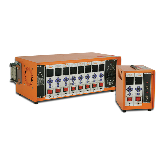
- Page 1 INCOE I Series IC-15A Temperature Control Module ® Quick Start Manual...
- Page 2 All rights reserved, errors and omissions excepted. © INCOE ® 2013 INCOE ® Corp. Global Headquarters 1740 E. Maple Road Troy, Mi 48083 USA T: 248-616-0220 E: tech.support@incoe.com www.incoe.com...
-
Page 3: Initial Start Up
Inspect all wiring to and from the PC Enclosure. With the power Off, install the individual Control Modules into the PC Enclosure. Note - to prevent electrical shock or damage to the I Series Controller, CONTrOllEr SpECIfICATIONS power to the PC Enclosure MuST be turned off when Input Power: 240/230 VAC single phase installing or removing Control Modules. - Page 4 INCOE I Series IC-15A Temperature Control Module ® Quick Start Manual MOdulE INTErfACE Interface features SOFT LED Indicates module in Soft Start phase OUT LED Indicates power output from module Displays Present Value (PV) of measured PV Display temperature (red four digit display)
-
Page 5: Basic Functions
INCOE I Series IC-15A Temperature Control Module ® Quick Start Manual OpErATION Basic functions Error Codes ▲ ▼ Error Code Display Description Adjust Set Value (SV) FU-1 Fuse 1 Disconnection ▲ ▼ Select unit digit for FU-2 Fuse 2 Disconnection... -
Page 6: Configuration Menu
- P Boost Power % 0 - 99.9% When an error occurs (e.g., Open TC, short), the module can send a signal to the PC Enclosure to sound a buzzer or alarm. Standard INCOE ® ▲ ▼ SOFt - P Soft Start Power % 0 - 99.9%... - Page 7 INCOE I Series IC-15A Temperature Control Module ® Quick Start Manual DATE Page 5 of 5 12/02/2013 INCOE ® Corp. Global Headquarters 1740 E. Maple Road Troy, Mi 48083 USA T: 248-616-0220 E: tech.support@incoe.com www.incoe.com...
- Page 8 INCOE Corporation ® Global Headquarters 1740 E. Maple Road Troy, Michigan 48083 USA T: + 1 (248) 616-0220 E: info@incoe.com Technical Support: T: + 1 (248) 556-7790 E: tech.support@incoe.com Customer Service and Sales: T: + 1 (248) 556-7770 E: customer.support@incoe.com...
Need help?
Do you have a question about the I Series and is the answer not in the manual?
Questions and answers