Advertisement
Quick Links
Advertisement

Related Manuals for Dynalco SST7000


Summary of Contents for Dynalco SST7000
- Page 1 5450 NW 33rd Ave, Suite 104 Fort Lauderdale, FL 33309 3211 Fruitland Ave Los Angeles, CA 90058 SST7000 SST7100 Speed Switch / Transmitter Installation and Operation Manual Rev. C P/N145F-13112 PCO – 00009270 (c) Copyright 2014, Dynalco Controls All Rights Reserved Published: April 29, 2015...
- Page 2 IMPORTANT - PLEASE READ BEFORE PROCEEDING! The Dynalco SST7000 series speed switch / transmitter is designed for reliable and rugged operation. This product has been designed and tested to meet the demands required in many industrial and hazardous locations. Performance of this product is directly related to the quality of the installation and knowledge of the user in operating and maintaining the instrument.
-
Page 3: Input Supply Voltage
1 relay trip output for over / under speed alarm or shutdown. Both models will accept a pulsed input from either a 2 or 3-wire speed sensor. Programming: The host software allows programming of the SST7000 series via a USB connection to a PC. Additional Features Repeater Output •... -
Page 4: Digital Input
3) DIGITAL INPUT (1): Dry contact closure for resetting latched relay 4) OUTPUTS: a. Meter Output: 0 – 1 mA meter output for loads up to 750 ohms b. Proportional Output: Proportional to input frequency range, configurable as: i. 4 – 20 mA into maximum 1K load And one of either: ii. -
Page 5: Alarm Indication
6) ALARM INDICATION: a. Open Pickup Alarm: LED indication if open pickup sensed Option to trip relay (SST-7100 only) b. Trip Indication: LED indication if a relay tripped condition 7) MEMORY: All configuration parameters retained if power lost 8) CONNECTORS: Removable Phoenix type 9) MECHANICAL: DIN rail mount package... - Page 6 Installation: The SST7000 series has an integral latch on the rear of the device for installation on a standard 35 mm DIN rail.
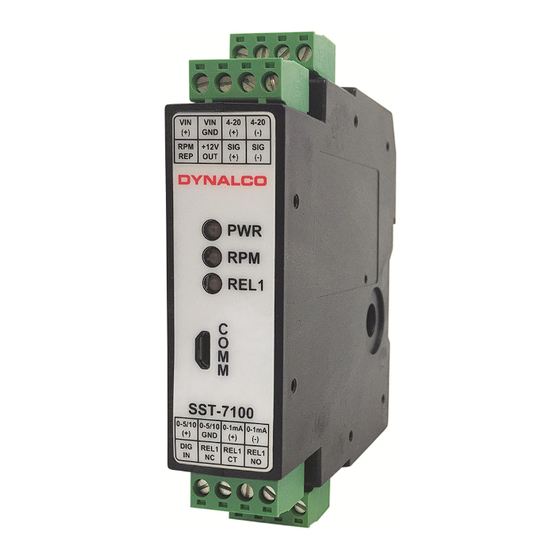
- Page 7 Terminal Connections All connections are made via the terminal blocks on the front of the unit. Description Description 10 - 36 VDC Supply (+) 0-5/10 0-5 or 0-10 VDC Proportional Output (+) Supply Ground (-) 0-5/10 0-5 or 0-10 VDC Proportional Output (-) 4-20 4-20 mA Proportional Output (+)
- Page 8 Outline Dimensions...
- Page 9 / setpoints. Once the configuration parameters are set, they can be programmed into the SST7000 and a spec file can be saved to the PC. This saved spec file can then be loaded into another SST7000 if desired. Additionally, there is an import function allowing uploading of the spec file from an SST7000 to the PC.
- Page 10 RPM Signal The RPM Signal needs to be programmed prior to all other settings. The SST7000 series is capable of accepting input signals from 2-wire (also known as variable reluctance) magnetic pickups as well as 3-wire (powered, TTL or hall-effect) type sensors.
- Page 11 Signal Lost (SST7100 only) The signal lost function is defined as the absolute maximum allowable period (time between input pulses in milliseconds) before an under speed relay is tripped. Similar to the Max Wave Duration described in the previous step, the Signal Lost is necessary for low speed applications where there is a programmed under speed trip.
- Page 12 Open Pickup (SST7100 only) The Open Pickup tab allows the user to select which relay (if any) will activate if an open pickup is sensed. • Enable o Check this box to enable Open Pickup option • Trip o Select Setpoint 1 for the SST7100...
- Page 13 Analog Output The analog output tab is used to define the RPM range of the proportional 4 – 20 mA output. • RPM Zero o Set to the RPM value corresponding to 4 mA output. o Normally set to 0 RPM but can be set to any value as long as it is lower than the RPM span.
- Page 14 Setpoint 1 (SST7100 only) The Setpoint 1 tab allows configuration of the relay setpoint and relay logic for the single relay on the SST7100. • Enable o Check this box to enable setpoint 1 • Relay Normal State o This is the normal relay state when not tripped o Either select normally Energized or normally De-Energized WARNING: For critical applications, it is highly recommended to configure the Relay Normal State as “normally...
- Page 15 Following initial configuration of the unit or any setting changes, you will need to select “Program” to program the new settings to the SST7000 / SST7100. Save File Selecting “Save File” allows the new settings to be saved to a file location on the PC.
- Page 16 Load File Any spec files that have been saved to the PC can be loaded to the SST7000 application by selecting “Load File.” Following this, you will need to select “Program” to write the new configuration to the SST7000. Import Settings Selection of “Import Settings”...
Need help?
Do you have a question about the SST7000 and is the answer not in the manual?
Questions and answers