Table of Contents
Advertisement
Quick Links
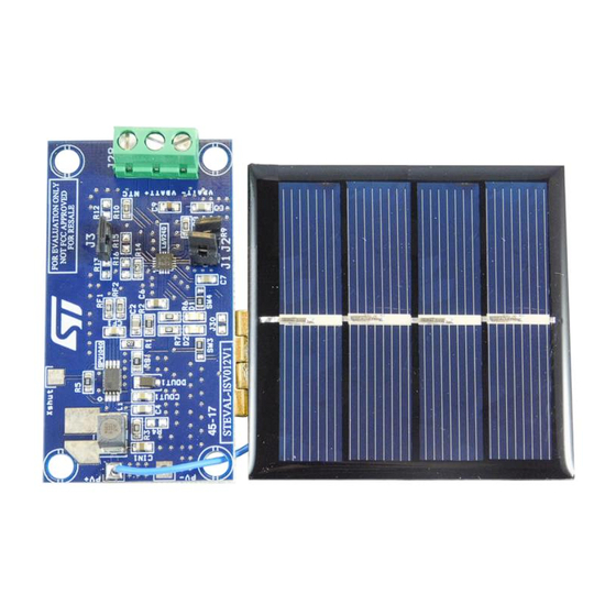
STEVAL-ISV012V1 lithium-ion solar battery charger
Introduction
The STEVAL-ISV012V1 evaluation board mounts an
stage and an
L6924D
powered by lithium-ion batteries and merges the SPV1040 power extraction capacity of the solar
module with the linear regulation of the L6924D for optimum battery charging load protection while
reducing the power dissipation at the bottom.
The board is designed to charge lithium-ion and lithium-polymer batteries with V
and it includes a 400 mWpk polycrystalline PV panel (SZGD6060-4P from NBSZGD) with V
and I
= 220 mA.
SC
According to specific application requirements, some components may be replaced
The PV panel can be replaced as long as V
The inductor L1 can be replaced, but consider its effect on the maximum peak current to ensure
that the input overcurrent limit is not triggered.
The maximum output current can be limited by replacing the current sensing resistor R
default).
Resistor R14, which limits the charge current threshold (500 mA by default).
a
For more details on component selection, refer to Application note AN3319, section "external component selection"
December 2017
(Li-Ion battery charger) as the output stage. It targets any portable application
Figure 1: STEVAL-ISV012V1 evaluation board
DocID022816 Rev 3
Application note
Domenico Ragonese; Alessandro Nicosia; Giovanni Conti
SPV1040
(solar energy harvester) for the input
< V
and I
< 1.65 A.
OC
BATT_max
S
AN4050
= 4.1 or 4.2 V
BATT_max
= 2.2 V
OC
a
:
(0 0Ω by
S
1/17
www.st.com
Advertisement
Table of Contents

Summary of Contents for ST STEVAL-ISV012V1
-
Page 1: Figure 1: Steval-Isv012V1 Evaluation Board
AN4050 Application note STEVAL-ISV012V1 lithium-ion solar battery charger Domenico Ragonese; Alessandro Nicosia; Giovanni Conti Introduction The STEVAL-ISV012V1 evaluation board mounts an SPV1040 (solar energy harvester) for the input stage and an L6924D (Li-Ion battery charger) as the output stage. It targets any portable application... -
Page 2: Table Of Contents
Contents AN4050 Contents SPV1040 operation ................4 L6924D operation ................6 L6924D operation in solar powered applications....... 6 Reference design description ............10 Schematic diagrams ..............12 Bill of materials ................14 Revision history ................16 2/17 DocID022816 Rev 3... - Page 3 Figure 13: V-I and P-V plot diagrams ....................... 10 Figure 14: Partial charge .......................... 11 Figure 15: Full charge ..........................11 Figure 16: STEVAL-ISV012V1 schematic, battery charge section ............12 Figure 17: STEVAL-ISV012V1 schematic, solar power optimizer section ..........13 DocID022816 Rev 3 3/17...
-
Page 4: Spv1040 Operation
SPV1040 operation AN4050 SPV1040 operation SPV1040 device is a low power, low voltage, monolithic step-up converter with an input voltage range from 0.3 V to 5.5 V, capable of maximizing the energy generated by a single solar cell (or fuel cell), where low input voltage handling capability is important. When combined with the L6924D, it provides an ideal solution for charging lithium battery packs with energy harvested from a very small solar panel. -
Page 5: Figure 4: Mppt Working Principle
AN4050 SPV1040 operation The voltage-current curve shows all the available working points of the PV panel at a given solar irradiation. The voltage-power curve is derived from the voltage-current curve by plotting the product V*I for each voltage generated Figure 4: MPPT working principle Voltage [V] Figure 5: SPV1040 internal block diagram START... -
Page 6: L6924D Operation
L6924D operation AN4050 L6924D operation L6924D is a fully monolithic battery charger dedicated to single-cell Li-Ion/polymer battery packs. It is designed with BCD6 technology and integrates all of the power elements (Power MOSFET, reverse blocking diode and sense resistor) in a small VFQFPN16 3 mm x 3 mm package. -
Page 7: Figure 7: Typical Charge Curve In Quasi-Pulse Mode
AN4050 L6924D operation To work in this condition, set the device charging current (with R14) higher than the maximum peak current of the PV panel. During the fast-charge phase, the output voltage of the SPV1040 that supplies the L6924D drops down to the battery voltage plus the voltage drop across the power MOSFET of the charger. -
Page 8: Figure 8: Battery Charging At Low Irradiation
L6924D operation AN4050 where Equation 2 ���� = �� × �� ������ ����(����) ������ is the current limit of the SPV1040, which depends on solar irradiation. Neglecting the voltage drop across the charger (ΔVMOS) when the device operates in this condition, its input voltage is equal to the battery’s, and therefore a very low operating input voltage (down to 2.5 V) is required. -
Page 9: Figure 10: Maximum Available Current Vs. Pin, 200 Mw Peak Pv Panel
AN4050 L6924D operation Figure 10: Maximum available current vs. Pin, 200 mW peak PV panel Vout = 4.5V Pin [mW] Figure 11: Maximum available current vs. Pin, 2 W peak PV panel Vout = 4.5V 800 1000 1200 1400 1600 1800 2000 Pin [mW] DocID022816 Rev 3 9/17... -
Page 10: Reference Design Description
3.4 V condition. After the one hour charge period time, the battery voltage reaches 3.8 V. Different results can be obtained if a different PV panel and/or battery are used Visit the support section on www.st.com if you require help regarding the use of different PV panels or batteries. 10/17... -
Page 11: Figure 15: Full Charge
AN4050 Reference design description The average overall power efficiency is approximately 85% (94% for SPV1040 and 90% for L6924D). Figure 14: Partial charge Time [m] Figure 15: Full charge Time [m] DocID022816 Rev 3 11/17... -
Page 12: Schematic Diagrams
Schematic diagrams AN4050 Schematic diagrams Figure 16: STEVAL-ISV012V1 schematic, battery charge section 470 Ohm 1k Ohm 1k Ohm Voprg Iend Vpre SHDWN Iprg Ipre Tprg 12/17 DocID022816 Rev 3... -
Page 13: Figure 17: Steval-Isv012V1 Schematic, Solar Power Optimizer Section
AN4050 Schematic diagrams Figure 17: STEVAL-ISV012V1 schematic, solar power optimizer section VIN_sns R5 0 Ohm R5 0 Ohm Ictrl+ Vrs+ Ictrl- Vrs- SPV1040 CON8B CON8B TSSOP8 Rs1 0 Ohm Rs1 0 Ohm PV + VOUT_SPV1040 VRs=50mV @ Imax 2.2M 2.2M Vctrl Vctrl =1.25V... -
Page 14: Bill Of Materials
Bill of materials AN4050 Bill of materials Table 1: STEVAL-ISV012V1 bill of materials Item Q.ty Ref. Part/Value Description Manufacturer Order code 400 mW, Vmp = 1.92 V; Imp = 200 SZGD6060- (polycris Solar panel NBSZGD mA; Voc = 2.2 V;... - Page 15 AN4050 Bill of materials Item Q.ty Ref. Part/Value Description Manufacturer Order code RF1, Thick film CRCW08051 1 kΩ, 0805 Vishay resistors K00FKEA Multilayer GRM21BR71 1 µF, 10 V, 0805 ceramic Murata C105KA01L capacitor SMD, 2.5 V, 25 mA, D1, D2 Green LED Kingbright KP-2012SGC...
-
Page 16: Revision History
Revision history AN4050 Revision history Table 2: Document revision history Date Version Changes 11-Jun-2012 Initial release. 21-Mar-2013 Updated Figure 5: SPV1040 internal block diagram. Text and formatting changes throughout document. 05-Dec-2017 Updated Section 5: "Bill of materials" 16/17 DocID022816 Rev 3... - Page 17 ST products and/or to this document at any time without notice. Purchasers should obtain the latest relevant information on ST products before placing orders. ST products are sold pursuant to ST’s terms and conditions of sale in place at the time of order acknowledgement.
Need help?
Do you have a question about the STEVAL-ISV012V1 and is the answer not in the manual?
Questions and answers