
Summary of Contents for Highway Care BG800
- Page 1 ENGINEERING YOUR SAFETY WWW.HIGHWAYCARE.COM Product and Installation Manual BG800 Australia & New Zealand Temporary & Permanent Applications Rev. C – 10/18 ©2018 Highway Care Limited. All Rights Reserved. Page 1 of 61...
-
Page 2: Table Of Contents
Delineators ............7 Installation ............16 Kerbs ..............7 Tools list ............16 Drainage ............7 Preparation ............ 18 Weight .............. 7 Getting Started ..........18 Rev. C – 10/18 ©2018 Highway Care Limited. All Rights Reserved. Page 2 of 61... - Page 3 Installation Checklist Example ....57 Other Operations ..........36 Permanent Applications ......59 Curved Barrier ..........36 Approvals ............60 Offset Ends to Barrier ........39 Contact Details..........61 Rev. C – 10/18 ©2018 Highway Care Limited. All Rights Reserved. Page 3 of 61...
-
Page 4: Introduction
Common uses connections to other barrier systems and crash include; cushions. Work zone protection • There is a standard system which is BG800 and Contraflow opportunities • two main system variations. These are MDS Controlled access •... -
Page 5: Design Considerations
Curved Barrier section of this manual. Median & Roadside Applications Environment BG800 can be impacted from either side of the BG800 should not be installed where there are barrier with no difference in performance. fixed objects that may affect performance of the Therefore, the barrier can be used in both barrier if impacted. -
Page 6: Length Of Need
ENGINEERING YOUR SAFETY WWW.HIGHWAYCARE.COM Length of Need Note: For use of BG800 on any ground conditions or anchors that are not shown in this drawing The length of need for BG800 is the total please contact Highway Care Ltd for further advice. -
Page 7: Anchoring
System (LDS). Delineators Reflective delineators can be attached to the side wall or top of the BG800 as required and at the relevant spacing’s. There are two options of delineators available, one a fixed reflector and the second a reflector with a flexible joint which Weight helps makes it resistant to breaking. -
Page 8: Safety Zone
Types section. Testing BG800 has been tested in accordance with NCHRP 350, MASH and BS EN 1317 parts 1 and 2 and has successfully demonstrated its capability to achieve the following containment and performance levels. NCHRP 350 TL-1, TL-2, TL-3 or TL-4, MASH TL-3 and BS EN 1317 Containment Level T1, T2, T3, N1, N2, H1 or H2. -
Page 9: System Types
ENGINEERING YOUR SAFETY WWW.HIGHWAYCARE.COM System Types BG800 is a versatile product with many system variations to suite different project requirements. The following section details various setup options. Dynamic Anchor Design System Test Performance Deflection Interval Speed Type Standard Level (km/h) -
Page 10: Calculated Deflections
− calculated deflections in metres at various performance levels for BG800 when anchored Where: as per system setup: (These calculations have Measured Maximum Dynamic Deflection: D • been based on actual test data). Measured Working Width: W •... -
Page 11: Standard - Nchrp 350 Tl-3
ENGINEERING YOUR SAFETY WWW.HIGHWAYCARE.COM Standard – NCHRP 350 TL-3 Below is a table showing the expected deflections of the TL-3 BG800 system if impacted at various angles and various speeds with a 2000kg Truck (60.0m Between Anchors). Deflection (m) Impact Speed... -
Page 12: Standard - Mash Tl-3
1.61 Lower Deflection System (LDS) – NCHRP 350 TL-3 Below is a table showing the expected deflections of the LDS TL-3 BG800 system if impacted at various angles and various speeds with a 2000kg Truck (12.0m Between Anchors). Deflection (m) -
Page 13: Minimum Deflection System (Mds) -
WWW.HIGHWAYCARE.COM Minimum Deflection System (MDS) – NCHRP 350 TL-3 Below is a table showing the expected deflections of the MDS TL-3 BG800 system if impacted at various angles and various speeds with a 2000kg Truck (6.0m Between Anchors, with T-Top). -
Page 14: Minimum Deflection System (Mds) - Mash Tl-3
WWW.HIGHWAYCARE.COM Minimum Deflection System (MDS) – MASH TL-3 Below is a table showing the expected deflections of the MDS TL-3 BG800 system if impacted at various angles and various speeds with a 2270kg Truck (6.0m Between Anchors, with T-Top). Deflection at Top (m) -
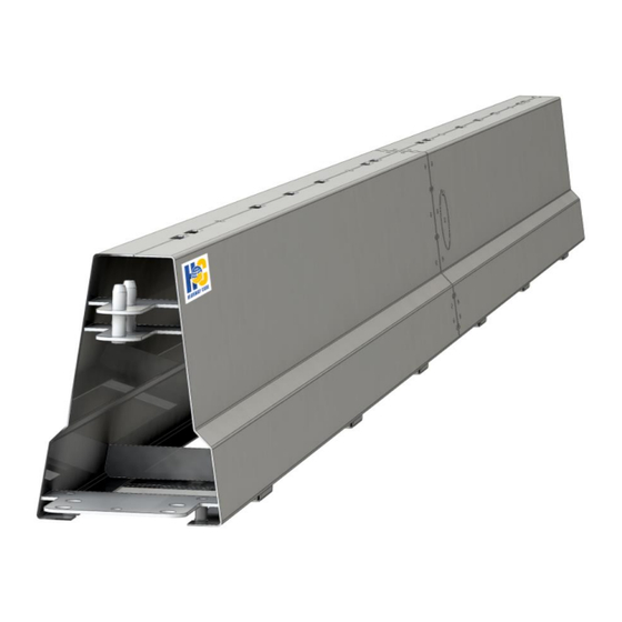
Page 15: Component Identification
6m gate section 1.4m gate post 3m gate hinge Notes: All M16 bolts used for connecting sections of BG800 together to be at least grade 8.8. Numerous extra components are available and bespoke options also. Please contact Highway Care for further information. -
Page 16: Installation
Such as lorry mounted crane or wheeled excavator. Must have suitable lifting Lifting Device capacity and reach to lift, manoeuvre and install BG800. It is also recommended that these cranes are remote control for ease of use. A two leg assembly with a 2500kg lifting capacity, each chain is 2m long c/w hook and locking clasp, and shortening clutch. - Page 17 Suitable of torques up to 300 Nm. C/W suitable 32mm socket Podger (round pry bar) Sledge Hammer To hammer in anchor pins. Cranked Crow Bar Useful for removing tight pins. Rev. C – 10/18 ©2018 Highway Care Limited. All Rights Reserved. Page 17 of 61...
-
Page 18: Preparation
The required performance level of the • that the area is clear of underground BG800. services. (The appropriate service providers The start, finish and alignment of the BG800. • may need to be contacted). Any additional anchorages required (e.g. to •... -
Page 19: Lifting Bg800
4.1 times the Male: 562 points and when these pieces are bolted 6m Section weight of 6m together to make up a normal section of BG800, Female 555 Section. there are four possible lifting points along its 2.0 times the length. -
Page 20: Using Tag Ropes
The point of the hook does not go into the chain link! Rev. C – 10/18 ©2018 Highway Care Limited. All Rights Reserved. Page 20 of 61... -
Page 21: Ancillary Lifting Devices
There are various alternative lifting devices that sure the hook is around the bar that runs can be used with BG800. See the Photo Example across the slot. NEVER HOOK ONTO THE section at the end of this manual for SHEET STEEL DIRECTLY. -
Page 22: Transport
A female terminal end, if required, will • usually be on the bottom layer in the centre the BG800. Confirm the barrier is put on the of the trailer with the terminal towards the delivery truck the right way around and the front of the trailer. - Page 23 Note: When loading barrier which has been angled at the bolted joint to follow a curve, these should be straightened prior to transport. Rev. C – 10/18 ©2018 Highway Care Limited. All Rights Reserved. Page 23 of 61...
- Page 24 3 layers of straps. barrier, 4 barriers per layer (12 in total). Note: It is not necessary to transport BG800 with Place the first layer directly on the trailer with the T-Top already attached. T-Top can be added as...
-
Page 25: Truck Mounted Cranes/Wheeled Excavator
• That the vehicle is on reasonably level • Stow the crane in such a way that it cannot • ground. move during the transit. Rev. C – 10/18 ©2018 Highway Care Limited. All Rights Reserved. Page 25 of 61... - Page 26 ENGINEERING YOUR SAFETY WWW.HIGHWAYCARE.COM Rev. C – 10/18 ©2018 Highway Care Limited. All Rights Reserved. Page 26 of 61...
-
Page 27: Terminal Installation
Sometimes when a long length of BG800 is Terminal Installation to be installed and site conditions allow, the BG800 is always secured at its start and end by installation can commence at any point along a full height terminal. When a full height... -
Page 28: External Anchor Shoe
4) Remove the 8 bolts (3 along each side and 2 on the end) from the end cap hood section of the barrier and lift off the terminal cover (approx 30kgs). Rev. C – 10/18 ©2018 Highway Care Limited. All Rights Reserved. Page 28 of 61... -
Page 29: Standard Section Installation
The barrier should be unloaded from the truck below. These assemblies are pre-installed on as detailed in the section Lifting BG800. If a truck the BG800 and the connected sections are mounted crane with remote operation is used, simply bolted together by attaching the nut into a minimum of a three man team is required. -
Page 30: Joining Bg800 Sections
BG800 and place plywood packers under the foot at the male end. If the BG800 still won’t sit flush, unhook the leg of the chain nearest the joint being made, bring the other chain leg vertical and lift and lower on this leg. -
Page 31: Intermediate Anchoring
The bolts should be tightened to a torque ranging between 100 and 200 Nm, i.e. normal spanner tight. Once the intermediate anchors have been fixed to the BG800, position the barrier in the usual way. After installation, drill through the intermediate... -
Page 32: Single Sided Intermediate Anchors
If other drills are used these may not very close to the BG800 that undermines the have this protection. The Hilti TE 70 series takes strength of the normal anchoring position. - Page 33 If the drill has ATC it needs to be only lightly held. Remove the drill from the hole frequently to clear the dust. For Rev. C – 10/18 ©2018 Highway Care Limited. All Rights Reserved. Page 33 of 61...
-
Page 34: Different Anchor Types Installation
100mm without resin at the top of the hole as this may need to be increased or decreased to suit each application. Rev. C – 10/18 ©2018 Highway Care Limited. All Rights Reserved. Page 34 of 61... -
Page 35: Barrier Removal
After removing the barrier/anchor, remove the anchor bolt sleeves which protrude from the Noise Pollution concrete. The BG800 installation process requires the use Resin anchors unscrew easily. Cut off the of trucks, cranes and drilling equipment for remaining studding. fixing the anchors. Whilst this type of plant and... -
Page 36: Other Operations
Radius the middle of a 12m section and retightening after "bending". 3. Using a BG800 0.6m long Angle Section TO FIND THE ANGLE PER 12 METRE LENGTH these can be specified with a 2.5°, 5° or 10° angle and are quickly installed using the standard QuickLink connections. - Page 37 5˚radius piece & 5 3 & 4 1.56 ˚ slotted plates As above but 3m + 3 & 4 1.56 3m = 6m overall Rev. C – 10/18 ©2018 Highway Care Limited. All Rights Reserved. Page 37 of 61...
- Page 38 ENGINEERING YOUR SAFETY WWW.HIGHWAYCARE.COM Achievable Radius Flexibility Roundabout Component Layout Example Rev. C – 10/18 ©2018 Highway Care Limited. All Rights Reserved. Page 38 of 61...
-
Page 39: Offset Ends To Barrier
QuickLinks to curve the BG800 layout to create a flare away from the traffic lane or a BG800 5° radius piece can be placed in the barrier run at the correct joint to create a flare. Use of 5°... -
Page 40: Anti-Gawk Screen
IMPORTANT highway/roads applications. This can be used to When screens are attached to BG800 give added security to private sites to deter contractors must ensure the anchor spacing unauthorised access. and type of anchors are adequate to allow Note: Please Contact Highway Care for further for the wind loading requirements. -
Page 41: Expansion Joints
For sites where the expansion of the ground the barrier when hit. This can be prevented by that the BG800 is to be anchored to is a concern securing the barrier either side of the expansion there is a special section of BG800 called a joint with intermediate anchors. -
Page 42: T-Top
BG800 adjacent to the first or last section of required length of T-top and connected using the splice connection, to bolt it A minimum of two lifting points must be used to the T-top. -
Page 43: Gate
Gate this joint makes the gate difficult to manoeuvre when opening and closing. A BG800 Gate can be installed in a length of BG800 at any pre-determined and pre-planned BG800 T-top is also required to be added to the point along its length within 24m of the start top of the barrier for the BG800 Gate point and end point. -
Page 44: Turning The Barrier Over
2) The centre of the barrier settles on the block clear of cross members and with only one side of the barrier supported by the block. Rev. C – 10/18 ©2018 Highway Care Limited. All Rights Reserved. Page 44 of 61... -
Page 45: Maintenance & Repair
Usually after a design impact there is little access), and a check that the fasteners are tight, damage to BG800 and it could continue to be this could be done by taping the fastener with a used without concern. If however the barrier hammer. - Page 46 If during loading or installation of the BG800 the installer finds a damaged section they are unsure of using, do not use it until it has been inspected and certified acceptable to use by a competent person.
-
Page 47: Photo Examples
ENGINEERING YOUR SAFETY WWW.HIGHWAYCARE.COM Photo Examples Standard Install Bridge Install LDS Install T-Top Transition Section MDS Install Variable Length Barrier Rev. C – 10/18 ©2018 Highway Care Limited. All Rights Reserved. Page 47 of 61... - Page 48 ENGINEERING YOUR SAFETY WWW.HIGHWAYCARE.COM Barrier Trailer Full height End Section Lifting Grab External Anchor Shoe Lifting Cradle Intermediate Anchor Rev. C – 10/18 ©2018 Highway Care Limited. All Rights Reserved. Page 48 of 61...
- Page 49 ENGINEERING YOUR SAFETY WWW.HIGHWAYCARE.COM Security Nut Installation Joining BG800 Gate Post & Hinge Joint Anti-Gawk Screen Security Fence Typical Impact Damage Rev. C – 10/18 ©2018 Highway Care Limited. All Rights Reserved. Page 49 of 61...
-
Page 50: Frequently Asked Questions
4) Does BG800 require anchoring? BG800 is an anchored system and must always be anchored as a minimum at the 8 anchor points in the terminal sections at the start/end of every run of barrier. Intermediate anchoring may also be required with the frequency dependent on the system used (Standard every 60m, MDS every 6m, LDS every 12m). - Page 51 10) What is the smallest run of barrier and the largest available? The minimum recommended installed length of BG800 is 18m between inner anchor shoes; i.e. for an installation with no approved crash cushion connected to the end terminal; the minimum total system length including terminals and anchors is 30m.
-
Page 52: Appendix
If conflict arises with details listed within this manual, then the conditions in state approval documents take precedence. Rev. C – 10/18 ©2018 Highway Care Limited. All Rights Reserved. Page 52 of 61... -
Page 53: Anti-Gawk Screen Foundation Pavement & Anchor Details
If conflict arises with details listed within this manual, then the conditions in state approval documents take precedence. Refer to drawing BG-70-38 for wind loading requirements. Rev. C – 10/18 ©2018 Highway Care Limited. All Rights Reserved. Page 53 of 61... -
Page 54: Risk Assessments
WWW.HIGHWAYCARE.COM Risk Assessments Whereas these Risk Assessments outline the basic hazards and risks involved with installing BG800, you must provide your own detailed Risk Assessment which will encompass your particular working environment and may require site specific information. Risk assessments, safe system of work method statements &... - Page 55 When working on a live carriageway, a safety zone is required between the working area and the live traffic lane. It is not possible to install BG800 unless such a safety zone is provided. It is suggested that a working area of not less than 0.5 metres will be required between the BG800 and the safety zone.
- Page 56 Death or injury as a result of All truck movements under control of Training manoeuvring truck competent banksman Injury from collision with Correctly installed traffic management Training passing traffic Rev. C – 10/18 ©2018 Highway Care Limited. All Rights Reserved. Page 56 of 61...
-
Page 57: Installation Checklist Example
Installed by; Project Number; Inspected by; BG800 Applicable Section; Yes or No Is the site suitable for BG800? Are the pavement conditions suitable? Are the anchors selected suitable for the pavement condition? Are all the components available? Do the anchor shoes have the lynch pin installed? - Page 58 ENGINEERING YOUR SAFETY WWW.HIGHWAYCARE.COM Other Information / Comments / Reference Drawing Please note any variations. Rev. C – 10/18 ©2018 Highway Care Limited. All Rights Reserved. Page 58 of 61...
-
Page 59: Permanent Applications
ENGINEERING YOUR SAFETY WWW.HIGHWAYCARE.COM Permanent Applications When BG800 is installed in permanent applications the following conditions apply; ABSORB 350 Crash Cushion is not to be • used as this is for temporary use only. Flat & Flag top pins are not to be used as •... -
Page 60: Approvals
Transport industry/Business-with-us/Approved-products-and- Queensland and Main suppliers/Traffic-engineering-and-road-safety- Roads approved-products.aspx https://www.mainroads.wa.gov.au/BUILDINGROAD Western S/STANDARDSTECHNICAL/ROADANDTRAFFICENGI Main Roads Australia NEERING/ROADSIDEITEMS/Pages/List_of_Approved _Road_Safety_Barrier_Systems.aspx#TOCh41 New Zealand https://www.nzta.govt.nz/resources/road-safety- New Zealand Transport barrier-systems/ Agency Rev. C – 10/18 ©2018 Highway Care Limited. All Rights Reserved. Page 60 of 61... -
Page 61: Contact Details
ENGINEERING YOUR SAFETY WWW.HIGHWAYCARE.COM Contact Details Visit: www.highwaycare.com Email: info@highwaycare.com Call: +44 (0)1622 734215 Rev. C – 10/18 ©2018 Highway Care Limited. All Rights Reserved. Page 61 of 61...
Need help?
Do you have a question about the BG800 and is the answer not in the manual?
Questions and answers