
Subscribe to Our Youtube Channel
Summary of Contents for Ceragon FibeAir IP-10C
- Page 1 FibeAir® IP-10C Installation Guide Document ID: DOC-00032280 Rev. H October 2012 Copyright © 2012 by Ceragon Networks Ltd. All rights reserved.
- Page 2 Registered Trademarks Ceragon Networks® is a registered trademark of Ceragon Networks Ltd. FibeAir® is a registered trademark of Ceragon Networks Ltd. CeraView® is a registered trademark of Ceragon Networks Ltd. Other names mentioned in this publication are owned by their respective holders.
- Page 3 Add list of test kits and updated Rami Lerner June 26, 2012 2012 SFP options table. October 28, Baruch Gitlin Added Appendix C: Connector Rami Lerner October 28, 2012 Pin-Outs and revised Appendix A: 2012 Mediation Device Losses, Ceragon Proprietary and Confidential Page 3 of 63...
-
Page 4: Table Of Contents
FibeAir® IP-10C Installation Guide Table of Contents 1. FibeAir IP-10C Overview .................. 9 2. General Installation Procedures ..............10 Required Tools for Installation ..................10 Transportation ......................10 Packing Inspection ....................... 11 Location of the IP-10C ....................11 Installation Components....................12 Available Adapters and Installation Kits ............... - Page 5 6. Appendix B: Test Kit Part Numbers .............. 61 7. Appendix C: Connector Pin-Outs ..............62 Management Connector Pin-Out ................. 62 Power Connector Pin-Out .................... 62 Ethernet 10/100/1000 Connector Pin-Out..............63 Craft Terminal Connector Pin-Out ................63 Ceragon Proprietary and Confidential Page 5 of 63...
- Page 6 är kopplad till kabel- TV nät kan i vissa fall medfőra risk főr brand. Főr att undvika detta skall vid anslutning av utrustningen till kabel-TV nät galvanisk isolator finnas mellan utrustningen och kabel-TV nätet. Ceragon Proprietary and Confidential Page 6 of 63...
- Page 7 Wenn andere Steuerelemente verwendet, Einstellungen vorgenommen oder Verfahren durchgeführt werden als die hier angegebenen, kann dies gefährliche Strahlung verursachen. Maschinenlärminformations-Verordnung - 3. GPSGV, der höchste Schalldruckpegel beträgt 70 dB(A) oder weniger gemäß EN ISO 7779. Ceragon Proprietary and Confidential Page 7 of 63...
- Page 8 What You Should Know The IP-10C is an all outdoor module, which is based on the FibeAir IP-10Q and RFU-C systems. The IP-10C is part of Ceragon’s outdoor system, using the same waveguide and accessories. Target Audience This guide contains technical information about IP-10C installation, and is intended for use by qualified Ceragon technical personnel at all levels.
-
Page 9: Fibeair Ip-10C Overview
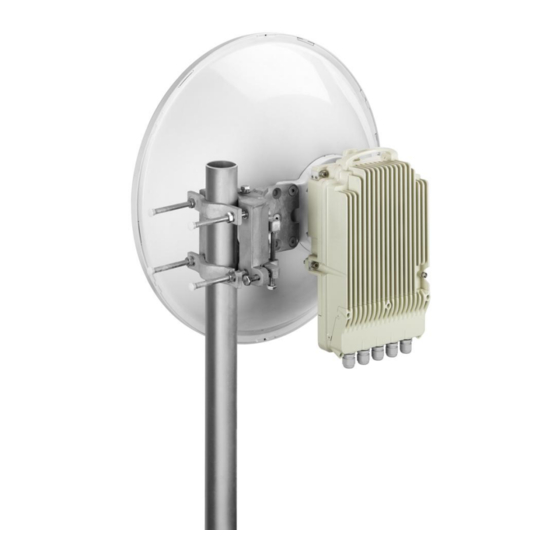
FibeAir® IP-10C Installation Guide FibeAir IP-10C Overview FibeAir IP-10C is a state-of-the-art all-outdoor unit which is fully software configurable and supports a broad range of capacities and interfaces. IP-10C – Front View IP-10C – Rear View IP-10C provides a powerful, reliable, and comprehensive solution for a variety of wireless network scenarios and requirements. -
Page 10: General Installation Procedures
If intermediate storing is required, the packed equipment must be stored in a dry and cool environment, and out of direct sunlight, in accordance with ETS 300 019-1-1, Class 1.2. Ceragon Proprietary and Confidential Page 10 of 63... -
Page 11: Packing Inspection
Otherwise, Ethernet and other SELV connections will turn to TNV. The IP-10C shall be installed in accordance with the national code and requirements of the country in which the IP-10C is being installed. Ceragon Proprietary and Confidential Page 11 of 63... -
Page 12: Installation Components
FibeAir® IP-10C Installation Guide Installation Components The following figures show the main components used in the IP-10C installation procedures. IP-10C Adapting Bar V/H Twist Coupler Holder with Coupler/OMT Remote Pole Mount Kit Ceragon Proprietary and Confidential Page 12 of 63... -
Page 13: Available Adapters And Installation Kits
42GHz RFU-C REMOTE RFU-C-PoleMount MOUNT KIT RFU- RFU-C ADAPTOR RFU-C6- RFU-C7_8- RFU-C13- C10_11- REMOTE MOUNT KIT RM_ADAPT RM_ADAPT RM_ADAPT RM_ADAPT Flx-WG-4FT- Flx-WG-4FT- Flx-WG-3FT- Flx-WG-3FT- Flx-WG-3FT- RFU-C WG Kit Flx-WG-4FT-6 Flx-WG-3FT-18-26 Flx-WG-3FT-28-38 10_11 Ceragon Proprietary and Confidential Page 13 of 63... - Page 14 OMT-INT-SH OMT-INT-SH OMT-INT-SH OMT-INT-SH OMT-INT-SH OMT-INT-SH INT-SH Xian Putian RFU-C6- RFU-C7_8- RFU- RFU-C13- RFU-C15- RFU-C18- RFU-C23- RFU-C26- RFU-C28- RFU-C32- RFU-C38- OMT-INT-X OMT-INT-X C10_11- OMT-INT-X OMT-INT-X OMT-INT-X OMT-INT-X OMT-INT-X OMT-INT-X OMT-INT-X OMT-INT-X OMT-INT-X Ceragon Proprietary and Confidential Page 14 of 63...
-
Page 15: Antenna Connection
UG383/U UG383/U If a different antenna type (CPR flange) is used, a flange adaptor is required. Please contact your Ceragon representative for details. Note: Conductive grease must be applied to the screws that connect the IP-10C to the antenna interface. -
Page 16: Adjusting For Horizontal And Vertical Polarization
Attach the iris using two M3 screws, according to the antenna polarization: For horizontal polarization, locate the holes above and below the letter “H” on the pins and fasten the two screws. Ceragon Proprietary and Confidential Page 16 of 63... -
Page 17: Connecting Flexible Waveguides To The Ip-10C
The following table provides the marketing models for the remote mount waveguide adaptor kits required, per frequency. Freq (WG standard) 6HGz (UBR70) 7-8GHz (UBR84) 10-11GHz (UBR100) 13GHz (UBR120) Remote Mount WG RFU-C6-RM_ADAPT RFU-C7_8-RM_ADAPT RFU-C10_11-RM_ADAPT RFU-C13-RM_ADAPT adaptor kit Remote Mount Kit RFU-C-PoleMount Ceragon Proprietary and Confidential Page 17 of 63... -
Page 18: Connecting The Waveguide In 6-13 Ghz Bands
2 Connect the waveguide to the antenna adaptor interface (the interface exposed by removing the iris). Use four screws (supplied with the waveguide kit) to fasten the waveguide end to the antenna adapter interface. Ceragon Proprietary and Confidential Page 18 of 63... - Page 19 FibeAir® IP-10C Installation Guide Note: It is normal for the flexible waveguide to reach the IP-10C at an angle of approximately 45°, as shown in the figure below. Ceragon Proprietary and Confidential Page 19 of 63...
-
Page 20: Cable Connections And Grounding Procedure
Optical cable Single Mode LC-LC 50m OUTDOOR 2.10.2 SFP Options SFP-GE-SX-EXT-TEMP SFP optical interface 1000Base-SX,EXT-TE SFP-GE-LX-EXT-TEMP SFP OPTICAL 1000Base-LX,EXT TEMP 2.10.3 Accessory Kits GBE_connector_kit 10 GBE connectors and protective rubber boots IP-10C_Glands_x5_kit 2. 5 IP-10C glands kit Ceragon Proprietary and Confidential Page 20 of 63... -
Page 21: Cap And Gland Installation
(see figure below) between the gland/gland cap and the cover. Use the large (1.6x10x200) slot screwdriver to tighten the cap. Use the locking pliers or 24mm wrench to tighten the gland. Ceragon Proprietary and Confidential Page 21 of 63... -
Page 22: Cable Installation - General
2 Connect the cables, as described in detail in the following sections: Preparing and Connecting a Cat5E Cable Connecting the Power Cable Connecting SFP Cable Connecting Bundled Cat5 Cable and Power Cable 3 Close the bottom cover using five M4 captive screws Ceragon Proprietary and Confidential Page 22 of 63... - Page 23 4 Thread the screws without fastening. After all five screws are threaded in the required location, tighten the screws diagonally with 2.6Nm torque. 5 Tighten the gland cap using 10 Nm torque Ceragon Proprietary and Confidential Page 23 of 63...
-
Page 24: Preparing And Connecting A Cat5E Cable
10 Insert the Cat5 plug boot into the cable with its face up. 11 Roll back the foil shield insulation and wrap the drain wire around the foil. Do not remove any insulation from the conductors. Ceragon Proprietary and Confidential Page 24 of 63... - Page 25 RJ45 plug and make good contact with the metal contacts in the RJ45 plug. 18 Push back the Cat5 plug cover on the connector plug. 19 Disassemble the relevant cap. Ceragon Proprietary and Confidential Page 25 of 63...
- Page 26 21 Connect the assembled connector into the IP-10C plug connector. 22 Once all the cables have been installed, close the small cover using five captive screws and tighten the gland cap with 10 Nm torque. Ceragon Proprietary and Confidential Page 26 of 63...
-
Page 27: Connecting Sfp Cables
3 Release the gland cap slightly. 4 Insert wires with connector one by one into the cable gland. 5 Disassemble the middle cap. 6 Insert the cable wires one by one into the middle hole. Ceragon Proprietary and Confidential Page 27 of 63... - Page 28 9 Insert the gland into the small cover and tighten until there is full contact between the gland and the cover. 10 Once all the cables have been installed, close the small cover using five captive screws and tighten the gland cap with 10 Nm torque. Ceragon Proprietary and Confidential Page 28 of 63...
-
Page 29: Connecting Bundled Cat5 Cable And Power Cable
5 Connect the grounding shield to the body with serrated washers, plain washer and M6 Nut. 6 Once all the cables have been installed, close the small cover using five captive screws and tighten the gland cap with 10 Nm torque. Ceragon Proprietary and Confidential Page 29 of 63... -
Page 30: Connecting The Power Cable
6 Insert the power cable wires into the power connector. 7 Match “+” and “–“to the red and black cord colors according to the power supply connection cord colors (for + and – locations, refer to the figure below). Ceragon Proprietary and Confidential Page 30 of 63... - Page 31 9 Plug in the power cable with connector into the IP-10C power connector. 10 Tighten the two front screws. 11 Once all the cables have been installed, close the small cover using five captive screws and tighten the gland cap with 10 Nm torque. Ceragon Proprietary and Confidential Page 31 of 63...
-
Page 32: Securing The Cables
For combined cables (see Connecting Bundled Cat5 Cable and Power Cable on page 29), the cable should be grounded to the antenna tower every 50m, using an SI-0391-0 grounding kit, IF RG-8 GRD KIT. Ceragon Proprietary and Confidential Page 32 of 63... -
Page 33: Grounding The Ip-10C
The user power supply GND must be connected to the positive pole in the IP-10C power supply. Any other connection may cause damage to the system! Important: For the warranty to be honored, you must install the IP-10C in accordance with the instructions above. Ceragon Proprietary and Confidential Page 33 of 63... -
Page 34: Surge Protection
IP-10C’s surge protection mechanism complies with surge immunity standard IEC 61000-4-5, level 4, provided the Ethernet cables were prepared according to the instructions in Preparing and Connecting a Cat5E Cable on page 24. Ceragon Proprietary and Confidential Page 34 of 63... -
Page 35: Ip-10C Configurations
After all four screws are threaded to the required location, tighten the screws starting from the bottom screws. 4 Connect the cables as described in Cable Connections and Grounding Procedure on page 20. Ceragon Proprietary and Confidential Page 35 of 63... -
Page 36: 1+0 Remote Mount Installation
6 Mount the flexible waveguide on the antenna, and tighten the screws and washers. 7 Connect the cables as described in Cable Connections and Grounding Procedure on page 20. Ceragon Proprietary and Confidential Page 36 of 63... - Page 37 5 Connect the flexible waveguide to the IP-10C antenna adaptor interface (the interface exposed by removing the iris). Note: It is normal for the flexible waveguide to reach the IP-10C at an angle of approximately 45°, as shown in the figure below. Ceragon Proprietary and Confidential Page 37 of 63...
- Page 38 Mount the flexible waveguide on the antenna, and tighten the screws and washers. 8 Connect the cables as described in Cable Connections and Grounding Procedure on page 20. Ceragon Proprietary and Confidential Page 38 of 63...
-
Page 39: 1+1 Hsb Direct Mount Installation
1 Mount the twist to the coupler using the O-Ring and four screws supplied in the Twist kit, and tighten the screws. Important: Make sure the polarization mounting direction of the twist to the coupler is according to the antenna polarization. Ceragon Proprietary and Confidential Page 39 of 63... - Page 40 M8 captive screws and washers, supplied with the IP-10C. Thread the screws without fastening. After all four screws are threaded in the correct location, tighten the screws starting from the bottom screws. Ceragon Proprietary and Confidential Page 40 of 63...
- Page 41 FibeAir® IP-10C Installation Guide Important! Pay attention to the polarization mounting direction. Ceragon Proprietary and Confidential Page 41 of 63...
-
Page 42: 1+1 Hsb Remote Mount Installation
RFU-C Remote Mount Adaptor kit, and tighten the screws. 2 Mount the IP-10C coupler to the RFU-C pole mount bracket using the four M8 screws and washers supplied with the RFU-C Coupler kit, and tighten the screws. Ceragon Proprietary and Confidential Page 42 of 63... - Page 43 7 Mount the flexible waveguide on the coupler, and tighten the screws and washers. 8 Place the O-Ring in the other end of the flexible waveguide flange groove. 9 Mount the flexible waveguide on the antenna, and tighten the screws and washers. Ceragon Proprietary and Confidential Page 43 of 63...
-
Page 44: 2+0 Single Polarization (Sp) Direct Mount Installation - Symmetrical Coupler
To install an IP-10C in a 2+0 SP direct mount configuration: 1 Remove the Extender from the Symmetrical Coupler by loosening and removing the four M4 screws and washers, as shown in following figure. Ceragon Proprietary and Confidential Page 44 of 63... - Page 45 Ring. The gasket should be mounted between the twist and the RFU-C Circulator/Symmetrical Coupler Kit. Important! Make sure the polarization mounting direction of the twist to the RFU-C circulator / symmetrical coupler is according to the antenna polarization. Ceragon Proprietary and Confidential Page 45 of 63...
- Page 46 M8 captive screws and washers, supplied with the IP-10C. Thread the screws without fastening. After all four screws are threaded in the correct location, tighten the screws starting from the bottom screws. Ceragon Proprietary and Confidential Page 46 of 63...
- Page 47 FibeAir® IP-10C Installation Guide Important! Pay attention to the polarization mounting direction. Ceragon Proprietary and Confidential Page 47 of 63...
-
Page 48: 2+0 Single Polarization (Sp) Remote Mount Installation - Symmetrical Coupler
To install an IP-10C in a 2+0 SP remote mount configuration: 1 Mount the IP-10C coupler to the RFU-C pole mount bracket using the four M8 screws and washers supplied with the RFU-C Symmetrical Coupler kit, and tighten the screws. Ceragon Proprietary and Confidential Page 48 of 63... - Page 49 6 Mount the flexible waveguide on the coupler, and tighten the screws and washers. 7 Place the O-Ring in the other end of the flexible waveguide flange groove. 8 Mount the flexible waveguide on the antenna, and tighten the screws and washers. Ceragon Proprietary and Confidential Page 49 of 63...
-
Page 50: 2+0 Dual Polarization (Dp) - Direct Mount Installation
1. Prior to the installation, follow the antenna manufacturer’s instructions to switch to a circular adaptor (remove the existing rectangular adapter, swap the O-ring, and install the circular adaptor in its place). Ceragon Proprietary and Confidential Page 50 of 63... - Page 51 4. Connect the iris to the IP-10C using two M3 screws, according to the OMT port polarization 5. Mount the adapting bar on the OMT holder using two M8 flat screws. Ceragon Proprietary and Confidential Page 51 of 63...
- Page 52 9 Tilt the entire assembly, to achieve maximum XPD (Cross Polar Differentiation). 10 Connect the cables and ground the IP-10C units, as described in Cable Connections and Grounding Procedure on page 20. Ceragon Proprietary and Confidential Page 52 of 63...
-
Page 53: 2+0 Dual Polarization (Dp) - Remote Installation
Mount OMT Adaptor #1 on the OMT, and tighten using four M4 screws and washers (supplied with the OMT adaptor kit). iii Mount OMT Adaptor #2 on OMT Adaptor #1, and tighten using four M4 screws and washers (supplied with the OMT adaptor kit). Ceragon Proprietary and Confidential Page 53 of 63... - Page 54 Mount the OMT adaptor, with its installed sealing gasket, on the OMT, and tighten using the four M4 screws and washers supplied with the OMT Adaptor kit. iii Mount the flexible waveguide without its gasket (only for the OMT side). Ceragon Proprietary and Confidential Page 54 of 63...
- Page 55 13 For 13 GHz (UBR120) to 42 GHz (UG383/U), connect the flexible waveguide and its gasket (supplied with the Flexible WG Kit) directly to the OMT port. 14 Connect the other end of the flexible waveguide to the IP-10C Radio port. Ceragon Proprietary and Confidential Page 55 of 63...
-
Page 56: Remote Mount Installation With An Imperial Waveguide
FLEXIBLE WG IMPERIAL KIT RFU-C REMOTE MOUNT ADAPTOR KIT Up to 15 GHz RFU-C REMOTE POLE MOUNT KIT Required Tools Metric offset hexagon key wrench set Imperial offset hexagon key wrench set Ceragon Proprietary and Confidential Page 56 of 63... -
Page 57: Remote Mount Installation With An Imperial Waveguide - 6-11 Ghz
4 Connect the Flexible Waveguide and Sealing Gasket supplied with the Flexible Waveguide Imperial kit to the RFU-C Adaptor. Tighten the screws supplied with the Flexible Waveguide Imperial kit. Ceragon Proprietary and Confidential Page 57 of 63... -
Page 58: Remote Mount Installation With An Imperial Waveguide - 13-15 Ghz
4 Connect the Flexible Waveguide and sealing O-Ring supplied with the Flexible Waveguide Imperial kit to the RFU-C Adaptor. Tighten the four screws supplied with the Flexible Waveguide Imperial kit. Ceragon Proprietary and Confidential Page 58 of 63... -
Page 59: Remote Mount Installation With An Imperial Waveguide - 18-42 Ghz
4 Connect the Flexible Waveguide and sealing O-Ring supplied with the Flexible Waveguide Imperial kit. Tighten the four metric screws supplied with the RFU-C Adaptor kit. Ceragon Proprietary and Confidential Page 59 of 63... -
Page 60: Appendix A: Mediation Device Losses
Integrated antenna 4+0 DP (OMT) Remote Mount Notes: The antenna interface is always the IP-10C interface. If other antennas are to be used, an adaptor with a 0.1 dB loss should be considered. Ceragon Proprietary and Confidential Page 60 of 63... -
Page 61: Appendix B: Test Kit Part Numbers
RFU-C7_8-TS/P RFU-C7_8-TS/X 10/11 GHz RFU-C10_11-TS/NP RFU-C10_11-TS/P RFU-C10_11-TS/X 13 GHz RFU-C13-TS/NP RFU-C13-TS/P RFU-C13-TS/X 15 GHz RFU-C15-TS/NP RFU-C15-TS/P RFU-C15-TS/X 18-26 GHz RFU-C18_26-TS/NP RFU-C18_26-TS/P RFU-C18_26-TS/X 28-38 GHz RFU-C28_38-TS/NP RFU-C28_38-TS/P RFU-C28_38-TS/X 42 GHz RFU-C42-TS/NP RFU-C42-TS/P RFU-C42-TS/X Ceragon Proprietary and Confidential Page 61 of 63... -
Page 62: Appendix C: Connector Pin-Outs
Not Connected Power Connector Pin-Out The power connector pin-out is as follows: Left Pin (#1) Right Pin (#2) -48V (return current) Note that right/left refers to viewing the panel from the front. Ceragon Proprietary and Confidential Page 62 of 63... -
Page 63: Ethernet 10/100/1000 Connector Pin-Out
IP-10Q’s craft terminal to a DB9 connector. RJ-45 Female Name Direction DB9 Cross- Connector Pin Connect SGND – Signal Ground RD – Receive Data TD – Transmit Data Ceragon Proprietary and Confidential Page 63 of 63...
Need help?
Do you have a question about the FibeAir IP-10C and is the answer not in the manual?
Questions and answers