Advertisement
Quick Links
Installation, Operation &
Maintenance Instructions
1200°C Tube furnaces (3-zone)
This manual is for the guidance of operators of the above Carbolite products
and should be read before the furnace is connected to the electricity supply.
Section
1.0
2.0
3.0
4.0
Error! Bookmark not defined.
5.0
6.0
7.0
8.0
9.0
Manuals are supplied separately for the furnace controllers
(and overtemperature controller when fitted).
Please read the controller manuals before operating the furnace.
types TZF
C
ONTENTS
Error! Reference source not found.
page
2
3
5
9
12
13
14
16
Advertisement

Related Manuals for VERDER Carbolite TZF Series


Summary of Contents for VERDER Carbolite TZF Series
-
Page 1: Table Of Contents
Installation, Operation & Maintenance Instructions 1200°C Tube furnaces (3-zone) types TZF This manual is for the guidance of operators of the above Carbolite products and should be read before the furnace is connected to the electricity supply. ONTENTS Section page Introduction Installation Operation... -
Page 2: Introduction
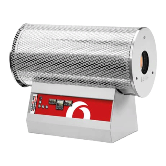
1.0 I NTRODUCTION Switches and Lights Instrument switch: when the instrument switch is operated the temperature control circuit is energised. Heat Switch: the switch disconnects power to the heating elements; unless this switch is off there is a danger of electric shock when inserting objects into the furnace Heat Light: the adjacent light glows or flashes to indicate that power is being supplied to the elements... -
Page 3: Installation
2.0 I NSTALLATION Unpacking & Handling When unpacking or moving the furnace always lift it by its base or by both ends of the main body. Never lift it by its work tube or the surrounding insulation. For the larger models, or where the furnace and control box are not fixed together, use two people to carry the furnace. - Page 4 Electrical Connections Connection by a qualified electrician is recommended. The furnaces covered by this manual may be ordered for single phase A.C. supply, which may be Live to Neutral non-reversible, Live to Neutral reversible or Live to Live. Some models can be supplied for three phase use;...
-
Page 5: Operation
3.0 O PERATION The instructions for operating the temperature controller are given in a separate manual. If the furnace is fitted with a time switch, see also the supplementary manual MS03. If cascade control is fitted, see the supplementary manual MS07. 3-zone Control Methods The models in this manual are typically designed to achieve an extended uniform temperature zone by the use of three control zones. - Page 6 the retransmitted set temperature. In level 2 of the end zone controller (see controller operating (local trim) and use the up down enter the desired positive or LOC.T instruction), scroll to negative difference to be added to the end zone set temperature. There is no need to alter the centre controller.
- Page 7 Tube Life A ceramic work tube may be cracked if workpieces are inserted too quickly or at temperatures below 900°C (when the tube is more brittle). Large pieces should also be heated slowly to ensure that large temperature differences do not arise. Poor thermal contact should be encouraged between the workpiece and the tube;...
- Page 8 Maintenance General Maintenance No routine maintenance is required. The outer surfaces may be cleaned with a damp cloth. Do not allow water to enter the interior of the case, tube or control box. Do not clean with organic solvents. Calibration After prolonged use the controller and/or thermocouple could require recalibration.
-
Page 9: Repairs & Replacements
5.0 R & R EPAIRS EPLACEMENTS Safety Warning – Disconnection from Supply Always ensure that the furnace is disconnected from the supply before repair work is carried out. Safety Warning - Refractory Fibrous Insulation Insulation made from High Temperature Insulation Wool Refractory Ceramic Fibre, (better described as Alumino Silicate Wool) (ASW) This product contains alumino silicate wool products in its thermal insulation. - Page 10 Thermocouple Replacement The coverings and guards which must be removed to gain access to the thermocouple depend on the model, its orientation (horizontal or vertical), and possibly other options and fittings. It is usually necessary to separate the furnace from its base or stand. On horizontal models (except TZF 12/38) one outer end-cap should be removed;...
- Page 11 Reverse the rest of the disassembly process. Take care to make all connections to the correct terminals. Do not overtighten the connectors in porcelain terminal blocks. Let the furnace heat up at its maximum rate to 900°C without interruption, and then soak for 1 hour.
-
Page 12: Fault Analysis
6.0 F AULT NALYSIS A. Furnace Does Not Heat Up The heating Check also that the SSR is working The HEAT light element has failed correctly is ON The controller The thermocouple has broken or has a The HEAT light wiring fault is OFF... -
Page 13: Circuit Details
7.0 C IRCUIT ETAILS Safety Switches type A: a 2-pole Heater Switch is fitted directly in the element circuit in models up to 16A rating. Safety Switch type B: a Heater Switch is fitted into the contactor coil circuit in models over 16A. Single Phase (example for TZF, control method A) Filter (if fitted) safety... -
Page 14: Fuses & Power Settings
Independent Zones (control method C) When this is ordered there are three independent thermocouples (instead of the four shown) connected to the three controllers; the words “master” and “slave” may be replaced by “centre” and “end”. Control by Broadcast comms (control method B) When this is ordered there are three independent thermocouples (instead of the four shown) connected to the three controllers;... - Page 15 The models covered by this manual are designed to run on 100% power, with the exceptions below. Model Volts: 200V 208V 220V 230V 240V 380V 400V 415V Equal zone models: TZF 12/38/400E TZF 12/65/550E Custom Models: TZF 12/25/550 TZF 12/38/550 TZF 12/75/550 TZF 12/75/900 Standard Model:...
-
Page 16: Specifications
9.0 S PECIFICATIONS Carbolite reserves the right to change specifications without notice Models Covered by this Manual MODEL Max. Max. Work Work Heated Uniform Temp. Power Tube Tube Length Zone Weight Bore Length Length (°C) (kW) (mm) (mm) (mm) (mm) (kg) Tube furnaces with a ceramic work tube wound with resistance wire TZF 12/38/400...
Need help?
Do you have a question about the Carbolite TZF Series and is the answer not in the manual?
Questions and answers