Table of Contents
Advertisement
Quick Links
Advertisement
Table of Contents

Summary of Contents for GDH Air Series
- Page 1 User Guide GDH™-Heat-Pump-Manager Air & Geo Series...
-
Page 2: Table Of Contents
Connection port Dimensions 4. GDH-Heat-pump Manager Main menu Menu structure Menu description 5. Setup the GDH Heat pump manager Functions Setup Select the heat pump working mode Select the heat pump operation mode Automatic Unit mode Setting temperatures for standard operation mode... -
Page 3: Warranty Und Guarantee
GDH heat pump. 230 Vac version: The power supply to the GDH-Heat-Pump-Manager terminal GDH heat pumps are subjected to strict should be separated from the power supply quality control tests in terms of functional to the other electrical devices (contactors... -
Page 4: Controller Board Drawing
2. Controller 2.1 Controller board drawing... -
Page 5: Controller In & Outputs
2.2 Controller In & Outputs 220 Volt Outputs Compressor 1 Compressor 1 Ground source pump Primary circuit pump Primary circuit pump DHW circuit pump DHW circuit pump Mix circuit pump Mix circuit pump External boiler / heater External boiler / heater Heating circuit pump Heating circuit pump DHW boiler/heater... -
Page 6: Preconnected I/O
2.3 Preconnected I/O Outputs: NO 220 Volt (6 Ampere) 1. pre-connected Primary circuit pump Connect your main circulation pump from the heat pump to your buffer tank. This pump is only working when the heat pump works. NO 4 2. pre-connected DHW circuit pump / 3-way valve The DHW circulation pump or 3-way-valve loads the Domestic Hot Water tank when the heat pump switches to DHW mode. -
Page 7: Connection Valves/Pumps
2.4 Connection valves/pumps The most important digital outputs are pre-connected inside the heat pump. Function Primary circuit pump DHW circuit pump / 3-way-valve Additional boiler / heater DHW heater 4-way-valve (Factory connected) 220V – 50 Hz – max. 6 A... -
Page 8: Id Digital Inputs (24 V)
2.5 ID - Digital inputs (24 V) Dew point heating circuit Dew point sensor for the cooling mode of the heating cirucuit. Dew point mixing heating circuit 2 Dew point sensor 2 for the cooling mode of the Mixing heating circuit EVU / Heat management Connection to the EVU device from your local energy supplier. -
Page 9: Y - Analogue Outputs
2.6 Y - Analog outputs Heating circuit 1 – Mix valve Valve for the heating mix circuit 1 Cooling pump / valve Connection for a cooling pump for the primary pump to the buffer tank circuit. Heating circuit 1 – Mix valve Valve for the heating mix circuit 1 2.7 B - Analog Inputs –... -
Page 10: Temperature Sensors Configuration
2.8 Temperature sensors configuration The heat pump manager needs different temperature sensors to manage the hydraulic functions. You need to activate some sensors for different functions. You can also set an offset for the sensor. In some cases the temperature must be calibrated, f.ex. when the sensor cable will be extended. -
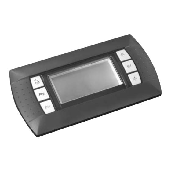
Page 11: Controller Display
3.0 Controller Display 3.2 Connection port 3.1 Display connection Connection of display by RJ11 plug on the backside of controller display. Connect the display with the controller board in your heat pump. 3.3 Dimensions Connector J7 on the controller board. Max. -
Page 12: Gdh-Heat-Pump Manager
4. GDH-Heat-Pump-Manager 4.1 Main Menu The graphic display control all heat pump functions. The display is shared in 4 areas. 1.) System Temperatures DHW = Domestic Hot Water temp. Outd. T= Outdoor temp. System T = Heating temp. 2.) Date, Time... -
Page 13: Menu Structure
4.2 Menu structure " " !On/Off " " Set point " !Clock / Bands " Inputs/Outputs " Alarm log " " Change board " Service a. Change language " b. Information " " c. Unit temp. control " " d. Hour counter "... -
Page 14: Menu Description
4.3 Menu description and date for all the associated functions. The time, date, time bands, closing periods and Unit On/Off holidays are set from the Clock/Time bands The unit status can be set from the main menu (C.). The screens are: menu (A.), based on the selection made. - Page 15 If the input or output has not been information concerning the GDH board set (no device connected), “----“ will be hardware. displayed. The related screens are shown below.
- Page 16 Trend card. G.f.c. Temperature control: this branch includes all the parameters relating to temperature control and modifiable during installation or service, except for those that BMS config. corresponding to the manufacturer area, which are found under the H.c. branch. G.f.a. Hour counter settings: used to set the G.f.d.
-
Page 17: Setup The Gdh Heat Pump Manager
5. Setup the GDH Heat pump manager 5.1 Functions The heat pump is delivered out with standard factory settings. After installation, you can switch it on for testing. The standard factory settings are: Mode: Heating Temperature: Heating 55 Heating / cooling / dhw / auto mode:... -
Page 18: Setup
5.2 Setup... -
Page 19: Select The Heat Pump Working Mode
5.3 Select the heat pump working mode GDH heat pumps can operate by a manual mode or by automatic mode selections. The user must select the mode on his own requirements and efficiency aspects. Heat pump is in “STAND BY” mode Heat pump works with “ON”... -
Page 20: Select The Heat Pump Operation Mode
5.4 Select the heat pump operation mode. You can select only this menu, when the heat pump is “OFF”. Automatic change over between Summer and Winter mode AUTO COOLING Only “COOLING” according “ON” temperatures HEATING Only “HEATING” according “ON” temperatures COOLING+DHW “COOLING”... -
Page 21: Automatic Unit Mode
5.5 Automatic Unit Mode Summer and winter changeover. You can see this menu only when you select operation mode “AUTO” in A01. Autom. Unit Mode Mode in Summer COOLING + DHW Mode in Winter HEATING + DHW Mode in summer Mode in winter... -
Page 22: Setting Temperatures For Standard Operation Mode
5.6 Setting temperatures for standard operation mode You can select the main temperatures for all heat pumps operation modes under this menu. Thermoreg. Unit Thermoreg. Unit Heat pump temperature Mix circuit 2 Nominal setpoint (ON) 12.0 °C Cooling: 38.0 °C! Heating: 12.0 °C Cooling:... -
Page 23: Setting Temperatures For Energy Saving Mode
5.7 Setting temperatures for energy saving operation mode You can select the main temperatures for all heat pumps operation modes under this menu. Thermoreg. Unit Thermoreg. Unit Heat pump temperature Mixcircuit 2 Energy save setpoint Energy save setpoint 12.0 °C Cooling: 12.0 °C Cooling:... -
Page 24: Automatic Summer And Winter Changeover
5.8 Automatic Sommer and Winter changeover You can set the criteria for the automatic change over when the heat pump is in “AUTO” mode. Set the temperature and the differential when the heat pump manager start the changeover. You can change the min. measuretime for the temperature change over. For example when the heat pump mangager measures 24h a temperature under the setpoint, the mode will be switched. -
Page 25: Heat Circuit Settings
5.10 Heat circuit settings Configuration GC03 Configuration Gc07 Heatcircuit: Heatcircuit: Type to calc. Setpoint ext. Air cooling cal. SP -Temperature external- ext. Air min ! SP inc. 20.0°C 10.0 K ext. Air max ! SP dec. 30.0°C 10.0 K Select the type of regulation: Cooling compensation Select the external Air temperature range: ! Temperature external... -
Page 26: Heating / Cooling Curve
5.11 Heating / cooling curve The temperature can be calculated for compensation according outdoor temperature or with a special room temperature display. Regulation based on the water inlet temperature. You need to setup the inlet temperature sensor direct into the buffer tank or the direct heating circuit. 5.12 DHW / Anti-legionella Mode The application allows the domestic hot water temperature to be controlled by both activating a three-way switching valve and a pump or the electric DHW heater. -
Page 27: Evu - Heat Management
Activation DHW electrical heater Domestic hot water integration boiler: In this case, the corresponding digital output NO8 (set using the parameter on screen Gfc03, which can also be set to replace the heat pump) is activated and deactivated according to a set point and differential defined on Gfc08. -
Page 28: Bivalent Mode
5.14 Bivalent mode Comparing cost effectiveness between heat pump and boiler The boiler can be managed either as an integration system or as an alternative to the heat pump. In the Manufacturer level, the efficiency of the heat pump is displayed on Ha08, while in the Service level to activate the function select “Enable boiler”... -
Page 29: Freeze Protection Geo
5.16 Freeze protection (Geo) This function is used to prevent potentially dangerous temperatures being reached for both the system and the geothermal loops. The values are measured using the outlet temperature probes (ground source and system primary circuit), setting an antifreeze set point and differential for the individual circuits. -
Page 30: Parameter Table
6. Parameter table A.ON-Off Unit Mask Display description Description Default Possible values Type Bms_Dir index address 0: OFF On/Off Selection if time bands 1: ON enabled 2: ENERGY SAVE Heat pump unit 3: AUTO " 0: DHW ONLY 1: AUTO "... - Page 31 Mask Bms_ Display description Description Default UOM Possible values index address Mixcircuit 2 Nominal setpoint (ON) B01b Comfort temperature set point 12.0 / °C / Hc18 Hc18 " (cooling) 53.6 °F mixcir Cooling: ucit 2 enabl Comfort temperature set point 38.0 / °C / Heating:...
- Page 32 Mask Display description Description Default UOM Possible values Type Bms_Dir index address " Month setting (mm) " Year setting (yy) Hour: Hour setting " Minutes setting " 0: MONDAY 1: TUESDAY 2: WEDNESDAY Scheduler settings 3: THURSDAY 4: FRIDAY 5: SATURDAY 6: SUNDAY 0: MONDAY 1: TUESDAY...
- Page 33 Mask Display description Description Default UOM Possible values Type Bms_Dir index address " Set end month, period 1 Start2 Set start day, period 2 " Set start month, period 2 0: OFF " Set type of set point, period 2 1: ON 2: ENERGY S.
- Page 34 Mask Display description Description Default UOM Possible values Type Bms_Dir index address " Set month, special day 6 0: OFF " Set type of set point, special day 6 1: ON 2: ENERGY SAVE 0: DISABLE DST: Enable daylight saving time 1: ENABLE Transition time: Time difference...
- Page 35 D.Input/Output Mask Bms_D Display description Description Default UOM Possible values index address B1 =Geothermal outlet temp. B1= Ground source water outlet temperature °C / -99.9 / -147.8 99.9 / 211.8 " °F B1= Heat exchanger B1 =Air exchang.temp.: temperature B2= Ground source water inlet °C / B2 =Geothermal inlet temp.: -99.9 / -147.8...
- Page 36 Mask Bms_D Display description Description Default UOM Possible values index address 0: Close 03=High press.sw.: ID3= High pressure switch unit) 1: Open ID4= Dew point sensor for the 0: Close 04=Dew point sensor 2 mixed heating circuit 1 1: Open 0: Close 05=EVU: ID5= EVU heat management...
- Page 37 Mask Bms_D Display description Description Default UOM Possible values index address 0: Off 10=4-way valve: NO10= 4-way valve 1: On NO11= Circulation pump for the 11=Mix circuit pump 2 mixed circuit 2 12=Crankcase heater NO12= Crankcase heater Y1= Mixing valve for mixed 01=Mix valve circ1: "...
- Page 38 Mask Bms_D Display description Description Default UOM Possible values index address Show High Delta P status - start >Max DP prevent start< disabled (blinking) Show pressure equalisation > Equalization < status (blinking) Working zone 1c - max speed > 90rps zone < 90 rps (Siam only) Operation Data barg...
- Page 39 Mask Bms_D Display description Description Default UOM Possible values index address Working zone 1a - reduced discharge temp limit (Siam Only: 0: 120ßC DischT Zone: Max. 1: 110ßC see chapter Siam BLDC compressor for more details) Power+ nß1 0: Stop Drive status: Show Power+ drive status 1: Run...
- Page 40 Mask Bms_D Display description Description Default UOM Possible values index address Drive temperature: °C / Power+ temperature 999 / 211 " °F [114] Power+ nß1 0: 4 1: 6 Show current PWM switching Operating switc. freq: 2: 8 frequency 3: 10 4: 12 [124] KHz Status register:...
- Page 41 Mask Bms_D Display description Description Default UOM Possible values index address Reserved 0: 0 " 1: 1 Reserved 0: 0 " 1: 1 Reserved 0: 0 " 1: 1 Reserved 0: 0 " 1: 1 Reserved 0: 0 " 1: 1 0: 0 "...
- Page 42 Mask Display description Description Default UOM Possible values Type Bms_Dir index address 37: ALD06 38: ALD17 39: ALD08 40: ALD09 41: ALD10 Hour alarm activated " " Minutes alarm activated " 0: --- 1: Geo flow switch 2: Sys flow switch 3: DHW pump overload 4: Pumps overload 5: Sys.
- Page 43 Heat pump manager Application code, version and Gb01 " date Ver.: Board type: Type of controller 0: GDH "Board seze: Board size 0: Pro Indicates the size of the memory Total flash: Kb 2048 9999 " on bank 0 of the controller (KB)
- Page 44 Mask Display description Description Default UOM Possible values Type Bms_Dir index address Power+ nß1 Power+ Boot loader Version " Boot release: FW Release: Power+ Software version " Gb05 FW Chekcsum: Power+ CRC Software " MC release: Power+ Motor version " Hardware ID: Power+ Carel HW ID "...
- Page 45 Mask Display description Description Default UOM Possible values Type Bms_Dir index address SP dec.: Temperature Setpoint decrease Heatcircuit: Temperature compensation ext. Air cooling cal. SP °C / - 50 Gc07 °F Outdoor temp. min. (Whe ext. Air min. !: temp eratur °C / ext.
- Page 46 Mask Display description Description Default UOM Possible values Type Bms_Dir index address Mixcircuit 1: Temperature compensation Room heating cal. SP Room temp. min. Room min ! SP inc. Gc13 (when room Temperature compensation differ Room min ! SP inc. Room temp. max. ence enabl SP inc.:...
- Page 47 Mask Display description Description Default UOM Possible values Type Bms_Dir index address ence Temperature compensation Room min ! SP inc. Room temp. max. enabl SP inc.: Temperature Setpoint increase SP dec. Temperature Setpoint decrease Factory setting Water temp. limits °C / Minimum Cooling temperature °F Cooling min:...
- Page 48 G.Service " e.BMS config. Mask Display description Description Default UOM Possible values Type Bms_Dir index address 0: --- 1: CAREL RS485 Communication prot.: BMS protocol setting 2: ModBus RS485 3: pCOload local 0: 1200 Ge01 1: 2400 Speed: baud BMS speed setting Baud 2: 4800 3: 9600...
- Page 49 G.Service " f.Service settings " b.Probe adjustement Mask Display description Description Default UOM Possible values Type Bms_Dir index address 0: NO Enable analogue input B1 1: YES Geotherm.outlet °C / Min_Diff_Temp_A Max_Diff_Tem Ofs: Probe B1 calibration value " °F AA** p_AAA** Ground source exchanger outlet °C /...
- Page 50 °C / Min_Diff_Temp_A Max_Diff_Tem Ofs: Probe B7 calibration value " °F p_AAA* Primary circuit outlet °C / Prb: -99.9 / -147.8 99.9 / 211.8 " temperature °F °C / 0: NO Enable analogue input B8 °F 1: YES Mixcirc. 2 °C / Min_Diff_Temp_A Max_Diff_Tem...
- Page 51 External or onboard EVD: Low barg S1 offset: 0 / 0 9.9 / 144.8 " pressure calibration offset / psig Gfb07 External or onboard EVD: Low barg S1 probe: 0 / 0 99.9 / 1448.9 " pressure transducer / psig (scre enabl External or onboard EVD:...
- Page 52 Mask Display description Description Default UOM Possible values Type Bms_Dir index address Type of activation of primary 0: INTEGRATE HP Request as: circuit integration 1: REPLACE HP DHW integration 0: NONE Select DHW integration 1: BOILER 2: EL. HEATERS Type: Gfc03 Type of activation of DHW 0: INTEGRATE HP...
- Page 53 Mask Display description Description Default UOM Possible values Type Bms_Dir index address F4 --:-- cent/kWh= Set start hour, time band 4 " Set start minutes, time band 4 " Set cost, time band 4 " Enable special energy cost 0: NO Enable special days days 1: YES...
- Page 54 Mask Display description Description Default UOM Possible values Type Bms_Dir index address Delay time for activation of the Delay on: s system heaters Differential from working set 10.0 / Max_Diff_Temp Diff.on DHW.: point for activation of DHW 50.0 _Thirty* integration heaters Differential from working set 5.0 / Max_Diff_Temp...
- Page 55 Mask Display description Description Default UOM Possible values Type Bms_Dir index address unit) Set outside temperature to 12.0 / °C / Max_Temp_AA Setpoint ext.temp.: Min_Temp_AA enable defrost activation 53.6 °F Defrost Setting Set temperature to start 7.0 / °C / Max_Temp_AA Gfc22 Set temperature start...
- Page 56 Mask Display description Description Default UOM Possible values Type Bms_Dir index address Gfc31 Defrost Setting Min value permitted during 20.0 999.9 " control to meet envelope conditions (screen Minimun rotor speed: enabled if AW unit and if set no stop Delta to increase speed when Delta speed: "...
- Page 57 Mask Display description Description Default UOM Possible values Type Bms_Dir index address °C / LOP treschh.: LOP – Low pressure range °F °C / MOP treschh.: MO – High pressure range °F Defrost Setting Enable boiler On in defrost 0: NO Plant integration phase 1: YES...
- Page 58 Mask Display description Description Default Possible values Type Bms_Dir index address Enable th-Tune: G.Service " f.Manual management Mask Display description Description Default UOM Possible values Type Bms_Dir index address Manual ground source pump 0: AUT NO2 Geo circ.pump: activation 1: MAN Gg01 Manual primary circuit pump 0: AUT...
-
Page 59: Alarm Management
The header of the Alarms table (paragraph 9.3) shows the alarm labels-codes: these are used to identify the origin of the alarm indicated by GDH Heat pump manager. To monitor active alarms simply press and the display will show the name (or names, if there is more than one active alarm);... - Page 60 The information shown on the screen relates to: 1. the chronological number of the event (this indicates the moment when the alarm was activated, that is, how “old” it is; E01 indicates the oldest alarm), 2. the time and date of the alarm, 3.
- Page 61 Alarm Display description Reset Delay Alarm relay Action Code Can be enable Stop primary circuit integration Automatic Immediate (Gfc02) boiler/heater ALR01 Position: ID7 System integ. boiler/heater alarm Manual Immediate Can be set (Gfa01) Stop DHW integration boiler/heater ALR02 Position: ID6 DHW boiler/heater overload from digital input Manual Immediate Stop the unit...
- Page 62 Note: alarm reset can be manual, automatic or selectable by parameter. In the first case, the user has to reset the alarm manually. In the second case, the alarm is reset automatically by GDH Heat pump manager which saves the event (these are less serious and potentially non-dangerous alarms).
-
Page 63: Optional Accessories
8. Optional Accessories 8.1 Room display The display is direct connected to a heating circuit. You can setup one display for the heating, mix 1 and mix2 circuit. Main functions ! Displays the actual room temperature ! Increases/Decreases the room temperature ! Shows the actual mode cooling/heating 8.2 Dew point Sensor In some conditions the pipes can be reach the dewpoint, when the heat pump is in... -
Page 64: Bms - Internet Module
8.3 BMS – Internet module GDH heat pump manager can be connected to various supervisory systems, using the following BMS communication protocols: Carel and Modbus. A BMS serial port serial port is used for the connection. The various connection protocols are managed using the following optional cards: Carel RS485: code PCOS004850 •... -
Page 65: Temperature Probe Resistant
9. Temperature probes resistance Table of temperature-resistance values for NTC sensor 10K@25°C t s i s i s t s i Max. Typical Min. Max. Typical Min. Max. Typical Min. °C °C °C 344.40 329.20 314.70 26.64 26.13 25.52 3.49 3.42 3.35 324.70... -
Page 66: Change The Battery
10. Change the battery...
Need help?
Do you have a question about the Air Series and is the answer not in the manual?
Questions and answers