
Summary of Contents for ATWELL VG OSG
- Page 1 VG OSG VG OSG Operation and Installation Manual Operation and Installation Manual Version 3.0 Version 3.0 Serving the lift industry since 1996 Operation and Installation Manual...
-
Page 2: Table Of Contents
Specification ......................7 General Description ..................7 Brake Mechanism ..................7 Governor Features ..................8 Governor Functions ..................9 Governor Pull-Through Forces ..............10 VG OSG Control Box (VGOSG-CB01) ............10 Signals ......................11 Handling, Transport and Storage ..............11 Components Supplied ................12 Optional Installation Pack ................12 VG Test Facility.....................12 RIG Instrumentation ..................13... - Page 3 VG OSG Dimensions ..................24 VG OSG Operational Flowchart ..............25 Normal Operation ..................26 Resetting The System..................26 By-Passing The System ................27 Test Deployment Of The VG OSG ..............27 Instructions For Rescue Operations/Hand Winding ........28 Regular Maintenance .....................29 Maintenance Instructions ................30 1. Controller (VGOSG-CB01A) ..............30 2.
-
Page 4: Overview
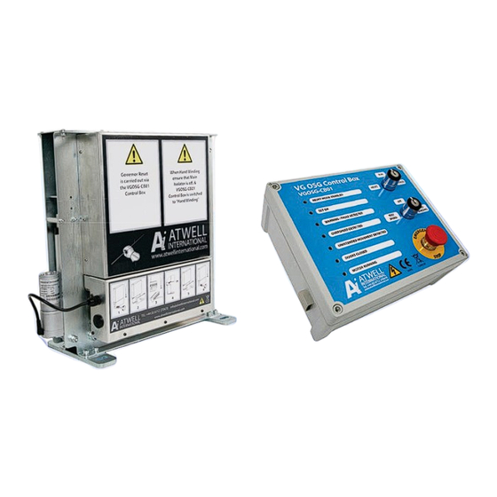
The VG OSG connects to the main lift control panel via its own specific control box (VG OSG – CB01). From here it can receive power and signals to tell if the lift doors are open, the state of the main motor contactor and the condition of the main safety circuit. -
Page 5: Safety Notes
No replacement parts other than those specified or supplied by the supplier Atwell International should be used as incompatible parts may risk the safe operation of the lift. Genuine spares are available within 24 hours at a reasonable cost. -
Page 6: Owners Obligations
This Warning Label is incorporated into the control box lid graphic to warn you of Live Electrical Parts, DO NOT REMOVE the lid if you are not a competent electrician capable of safely assessing the potentially dangerous internal connections. Atwell International Limited... -
Page 7: Specification
Brake Mechanism Please refer to drawing “VG OSG General Overview – fig 8 pg 21” which illustrate the mechanical assembly and the “Scott – Russell” linkage respectively. The drop weight CDS1703 is pivoted on one end of links CDS01708 and pivoted jaw CDS01716 at the other end. -
Page 8: Governor Features
The governor can be fitted with a “safety” switch in accordance with EN81 as an optional extra. This will be actuated by the handle on the reverse side of the governor. Atwell International Limited... -
Page 9: Governor Functions
The VG over-speed governor has integrated the established and certified circuitry of the unintended movement detection system used with the VG rope brake. However, the circuitry has been upgraded to comply with the requirements of annex F of EN81-20/50:2014. VG OSG Version 3... -
Page 10: Governor Pull-Through Forces
VG OSG in the event of a deployment or the need to carry out hand winding operations. So to prevent any unauthorised tampering or resetting or bypassing of the system a key is used. -
Page 11: Signals
Please return them to Atwell International for examination and re-test. The VG OSG and the VGOSG-CB01 should never be lifted or carried by their cables. They should never be allowed to get wet or exposed to moisture. -
Page 12: Components Supplied
• Manual & Documentation pack. • 4 keys. Optional Installation Pack An installation pack is also available from Atwell International but is not included as standard. This pack includes: • 10mtrs of 18 core CY/SY Cable • 5mtrs of 8 core screen cable •... -
Page 13: Rig Instrumentation
These results are then used to derive the salient points indicated in Figure F.2 of the code. A dynamic profile of a typical test is illustrated in Figure 2. VG OSG Version 3 13... -
Page 14: Rig Operation
Figure 3 14 Atwell International Limited... -
Page 15: Analysis Of Results
CE Plate Each VG OSG has a unique serial number Lift Running Speed Trip speed of the VG OSG 120% > than Nominal Speed Warning speed 110% > than the nominal speed Distance that the Unintended movement has been set at. -
Page 16: Installation
Figure 5 The enclosure weighs approximately 5 kg, it is supplied with 4 x M4 screws and rawl plugs to secure this control box to the wall. 16 Atwell International Limited... -
Page 17: Wiring
(input wiring from the main controller may be different colour) and warning symbols are displayed, this is so that you can easily identify them as potentially live, check them and beware of them. VG OSG Version 3 17... - Page 18 F1 (FS201) = Battery 1.25Amps Live! b. F2 (FS202) = 12v Internal Power Supply Unit 2.5Amps Please check rating against labels of each fuse. c. F3 (FS203) = 12v Relays / 12v Supply to VG OSG / 12v Output 2.5Amps F1 = Internal Power Supply 1.25Amps ...
- Page 19 The operation of these switches is essential to enable the VG OSG to operate safely, i.e. if a cable is broken or the lift over speeds the VG OSG will be FAIL SAFE. i.e. any problems, the VG OSG will activate.
-
Page 20: Wiring Diagram
12v DC Supply 0.5mm 19 -28 Optional Rope Brakes 1.5mm The VG OSG will always mechanically engage safety gears but options are available for additional electro mechanical brakes such as the VG rope brake. MAIN LIFT Options available are: CONTROL PANEL... -
Page 21: Connection Overview
VG OSG Version 3 21... -
Page 22: Door Contact Wiring Options (12V Circuit)
22 Atwell International Limited... -
Page 23: Mechanical Installation
The VG OSG should now be roped with an appropriate 8mm governor rope with a Tensile Grade of between 1570N/mm² to 1770N/mm². You must ensure that the rope follows the path shown in the diagram below and runs squarely in the pulley groove. -
Page 24: Vg Osg Dimensions
VG OSG Dimensions Reset Handle 300mm Pulley Grooved for 8mm Rope Shaft for optional hollow shaft encoder Cable entry Standard Mounting Feet Other options are available Shown without Guarding Figure 9 - VG OSG 24 Atwell International Limited... -
Page 25: Vg Osg Operational Flowchart
VG OSG Operational Flowchart VG OSG Version 3 25... -
Page 26: Normal Operation
• Insert the key into the reset/run/bypass switch. • Turn the key first to the bypass position and then back to the reset position and leave it there whilst the VG OSG resets. o The actuator will operate and drive the drop weight up... -
Page 27: By-Passing The System
To “BYPASS” the system you will disable the unintended movement detection function, but if the lift over speeds then the VG OSG willl be deployed. This function is purely for testing and maintaining the lift. When in this mode a sounder will beep every 30 seconds, to remind you that it cannot be left in this mode. -
Page 28: Instructions For Rescue Operations/Hand Winding
7. When the “SET OK” LED is illuminated, turn the key switch to “RUN”. 8. Turn the second key switch to “Hand winding”. 9. The VG OSG will now monitor for overspeed to a maximum mechanical trip of 0.4m/s and electrical trip of 0.3m/s. -
Page 29: Regular Maintenance
No replacement parts other than those specified or supplied by the supplier (Atwell International) should be used as incompatible parts may risk the safe operation of the lift. Genuine spares are available within 24 hours at a reasonable cost, but if they are needed quicker than exact same or equivalent parts may be sourced locally once the exact specification of those parts has been obtained and you have suitably assessed the implications of using non-standard parts. -
Page 30: Maintenance Instructions
Check the correct functioning of the Run / Reset / Bypass Key Switch Check the correct functioning of the Electric safety devices. Check the deployment of the VG OSG. Check the correct functioning of the Alarm / Error signals Check the unintended movement detector functions... -
Page 31: Definitions
Safety Components Components which are defined as safety components in the EU Lifts Directive (2014/33/EU). Competent Maintenance Person Persons with the knowledge, technical ability and equipment able to perform the tasks allocated to them without danger. VG OSG Version 3 31... - Page 32 • Divertors • Overspeed Governors • Tension Weights Sliding Guide Shoes • Guide Rails • Buffers • Compensation Chains Atwell International Ltd Ball Mill Top Business Park Hallow Worcester WR2 6PD United Kingdom Telephone +44 (0)1905 641881 info@atwellinternational.com Copyright© Atwell International Limited. All rights reserved.
Need help?
Do you have a question about the VG OSG and is the answer not in the manual?
Questions and answers