
Related Manuals for Bedford B503DSL Series


Summary of Contents for Bedford B503DSL Series
- Page 1 B503DSL Series Solar Photovoltaic Pump Controller Instruction Manual GUANGZHOU BEDFORD ELECTRIC EQUIPMENT CO.,LTD. V2.0.0...
-
Page 2: Table Of Contents
CONTENTS PREFACE............................I SAFETY PRECAUTIONS....................... II 1 SPECIFICATION........................ 1 1.1 Output 3AC 380V......................1 1.2 Output 3AC 220V......................1 1.3 Description of Name Plate....................2 1.4 Selection Guide....................... 2 1.5 Parts Description......................3 1.6 External Dimension......................5 2 INSTALLATION........................6 2.1 Installation Space......................6 3 WIRING..........................7 3.1 Schematic........................ -
Page 3: Preface
PREFACE Thanks for choosing our product, we will supply you with considerate service as well as ever. This product is suitable for solar photovoltaic pump system, aimed at environmental and economy market, to replace battery with retain water and without any battery components. Photovoltaic Pump Controller receives the DC which produced by Solar Modules and then transform into AC to drive all kinds of pump directly. -
Page 4: Safety Precautions
SAFETY PRECAUTIONS B503DSL is a new power electronic product, please read the operation manual carefully before using to keep your safety and make sure proper operation. In this manual, the safety precautions were sorted to “WARNING” and “CAUTION”. WARNING: Wrong using may result in death or serious personal injury. !... -
Page 5: Specification
1 SPECIFICATION 1.1 Output 3AC 380V Maximum input DC voltage 800VDC Recommended DC input voltage range 420~720VDC Recommended input working voltage 540VDC The number of Input port Rated output voltage 3AC 380V Output frequency range 0~600Hz Cooling method Air cooling This controller should be installed with altitude of lower than 1000m. -
Page 6: Description Of Name Plate
1.3 Description of Name Plate B503DSL-4010 Power Symbol Current Vector Control 010—10HP/7.5kW Controller 015—15HP/11kW Output Voltage Class 4—380V 2—220V Figure1.1 Nameplate of controller 1.4 Selection Guide 1)Output 3AC 380V Rated Output Rated Input Rated Output Motor Power Model No. Size Power(kW)... -
Page 7: Parts Description
2)Output 3AC 220V Rated Output Rated Input Rated Output Motor Power Model No. Size Power(kW) Current(A) Current(A) (kW) Output 3AC 220V B503DSL-2001 0.75 0.75 B503DSL-2002 B503DSL-2003 11.0 B503DSL-2005 17.0 B503DSL-2007 21.0 B503DSL-2010 31.0 B503DSL-2015 11.0 43.0 11.0 B503DSL-2020 56.0 15.0 B503DSL-2025 18.5 71.0... - Page 8 Figure 1.3 Parts of controllers (18.5kW and above) Figure 1.4 Dimension(0.75~15kW) Figure 1.5 Dimension(18.5~110kW)
-
Page 9: External Dimension
Figure 1.6 Dimension (132~315kW) 1.6 External Dimension Power A(mm) B(mm) H(mm) W(mm) D(mm) Installation Size Installation Dimension Hole (mm External Dimension (kW) 0.75~2.2 169.6 179.6 120.1 150.3 4~5.5 147.4 194.5 7.5~15 205.6 303.6 193.5 18.5~30 37~55 564.5 75~110 738.5 H(witho 1233 1275 13.0... -
Page 10: Installation
2 INSTALLATION 2.1 Installation Space Figure 2.1 Safe space Figure 2.2 Installation of multiple controllers Notice: Add the air deflector when apply the up-down installation. -
Page 11: Wiring
3 WIRING 3.1 Schematic Photovoltaic cell Water Tank B503DSL Well User Water pump Figure 3.1 Photovoltaic water supply system... -
Page 12: Solar Cell Array Power Supply
3.2 Solar cell array power supply Photovoltaic cell B503DSL Attention: B503DSL 2001~2003 Wiring : The positive pole connect to(+) , the negative pole connect to(N) (+) the positive pole the negative pole Wiring 4001~4003 : The positive pole connect to(+) , the negative pole connect to(R) (+)... -
Page 13: Solar Cell Array And Ac Power Supply
3.3 Solar cell array and AC power supply Note: if there is no protection diode connected to the end of the photovoltaic DC input, it is forbidden to close the switches (Q1 and Q2) at the same time, otherwise, it will damage the Photovoltaic cell module of photovoltaic cell B503DSL... -
Page 14: Specifications Of Breaker, Cable
photovoltaic cell, you only need to turn off “Q1”firstly and then close “Q2”. Main circuit terminal functions are summarized according to the terminal to the terminal symbols in the following table. Wire the terminal correctly for the desired purposes. Terminal Symbol Function Description R、S、T Terminals of 3 phase AC input... -
Page 15: The Wiring Of Water-Level Automatic Control
B503DSL-4180 B503DSL-4200 B503DSL-4250 B503DSL-4280 B503DSL-4300 150x2 B503DSL-4340 150x2 B503DSL-4380 1000 185x2 B503DSL-4430 1200 240x2 Please contact company for other specification. 3.5 The wiring of water-level automatic control 3.5.1 The wiring to prevent pump from anhydrous idling 3.5.1.1 The wiring for floater water-level switch connected by cable The common port, which using floater water-level switch connected by cable, is fed to the terminal “COM”... - Page 16 and its common wire is connected to the terminal “COM” of B503DSL controller. At the same time, the low level-water wire is connected to the terminal “S1” of B503DSL controller and the high water-level wire is connected the terminal “S2”. If the NC was selected, the parameter F0.12 should be set as follow:S1=1, S2=1.
-
Page 17: The Wiring Of Reservoir
Notice : if only use one detection signal of water-level in the wells, “S1” and “S2” must be connected together by conductor. 3.5.2 The wiring of reservoir 3.5.2.1 The wiring for floater water-level switch connected by cable The common port, which using floater water-level switch connected by cable, is fed to the terminal “COM”... - Page 19 3.5.3 The wiring for floater water-level switch mounted on a side The floater water-level switch mounted on a side is the normally open contact to output and its common wire is connected to the terminal “COM” of B503DSL controller. At the same time, the low level-water wire is connected to the terminal “S3”...
-
Page 20: Operation
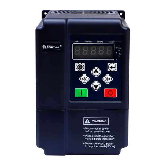
4 OPERATION 4.1 Keypad Description 4.1.1 Keypad schematic diagram Fuction indicator light Unit indicator light Digital display Program/Escape Data enter key Right Shift key Left Shift key Run key Stop key/Fault reset key Digital modify key Figure 4.1 Keypad schematic diagram 4.1.2 Key function description Button Symbol Name... -
Page 21: Indicator Light Description
Button Symbol Name Function Description Run Key Start to run the controller in keypad control mode In running status, can be used to stop the controller. Stop/Reset key When fault alarm, can be used to reset the controller in any control mode 4.1.3 Indicator light description 4.1.3.1 Function Indicator Light Description Indicator Light Name... -
Page 22: Fault Reset
automatically; while pressing will directly return to the second-class menu without saving the parameters, and keep staying at the current function code. 4.2.2 Fault reset If the controller has fault, it will prompt the related fault information. User can use to reset the fault. -
Page 23: Parameter Function
Reference frequency DC bus voltage Output voltage Output current Output torque Output frequency 5 PARAMETER FUNCTION Function Factory Name Description code setting 0: Water-level automatic control through keypad start/stop Run command F0.00 1: Water-level automatic control source 2: Manual control through keypad Upper F0.01 frequency... - Page 24 Function Factory Name Description code setting Restart delay Restart delay time after power on. Please refer to description F0.03 10.0s time of F0.13 when using Output Only DC bus voltage 100~900V(OUTPUT 220V series) 200V threshold is greater than the F0.04 voltage after value of F0.04 to give 100~900V(OUTPUT 380Vseries)
-
Page 25: Initial Debugging
Function Factory Name Description code setting F0.16 Reserve 0: No action Restore F0.17 1: Restore factory setting parameter 2: Clear fault records Maximum F0.18 output F0.02~600.00Hz 50.00Hz frequency Third latest 0: No fault F0.19 fault type 1: IGBT Ph-U fault (OUT1) 2: IGBT Ph-V fault (OUT2) Second latest F0.20... - Page 26 Modify the motor-pump parameters and start voltage: Modify these parameters (F0.05, F0.06, F0.07, F0.08, F0.09, F0.10) according to the parameters of solar cell array and the pump nameplate parameters. (According to the situation to adjust the F0.02, F0.04) Confirm the motor-pump wiring: 1.
-
Page 27: Trouble Shooting
7 TROUBLE SHOOTING 7.1 Fault and trouble shooting Fault Fault Type Reason Solution Code IGBT Ph-U OUT1 fault 1. IGBT module fault; 1. Ask for support; IGBT Ph-V 2. Malfunction caused by OUT2 2. Inspect external equipment and fault interference; eliminate interference 3. -
Page 28: Common Faults And Solutions
Fault Fault Type Reason Solution Code 7. Power module bridge is damaged; 8. Control board is abnormal 1. Wires or connectors of control 1. Check the wiring and connectors; Current board are loose; 2. Ask supplier for support; detection fault 2. -
Page 29: Maintenance
8 MAINTENANCE WARNING ! Maintenance must be performed according to designated maintenance methods. Maintenance, inspection and replacement of parts must be performed only by authorized personnel. After turning off the main circuit power supply, waiting for 10 minutes before performance maintenance or inspection. -
Page 30: Periodic Maintenance
◆Fan: Must be replaced when using up to 20,000 hours; ◆Electrolytic Capacitor: Must be replaced when using up to 30,000~40, 000 hours. 8.4 Warranty For B503DSL series controller, our company provides 12 months warranty after the date of leave factory. - Page 31 *Tips: In fact, the application of the product is closely associated with solar sell and environment. only you correctly preset the parameters of solar cell and additional use of the parameters (“F0.02 and F0.04” ) the highest utilization efficiency can be achieved. 1.
-
Page 32: The Physical Wiring Diagram
9 THE PHYSICAL WIRING DIAGRAM Appendix:1. B503DSL 2001,2002,2003 Wiring Diagram as below shown The notes below should be considered for the AC debug Power On Sequencing: Disconnect Q2 firstly, and then wait at least 5 minuets until controller discharge (or digital LED and all indicators extinguish ), then close Q1. - Page 33 2. B503DSL 4001,4002,4003 Wiring Diagram as below shown...
- Page 34 3.B503DSL4005,4007 Wiring Diagram as below shown...
- Page 35 4.B503DSL 4010,4015,4020 Wiring Diagram as below shown...
- Page 36 Agent:...
Need help?
Do you have a question about the B503DSL Series and is the answer not in the manual?
Questions and answers
ااريد دليل المستخدم توجد فيه البرامج المخفيهة
F00.0كم معلماته
The Bedford B503DSL Series specifications include:
1. Output Voltage Class:
- 4: 380V
- 2: 220V
2. Power Range:
- From 0.75 kW to 315 kW
- Example models:
- B503DSL-20010: 0.75 kW, 5.0 A input, 4.5 A output
- B503DSL-4430315: 315 kW rated output power
3. Output: 3-phase AC (3AC220V or 3AC380V depending on model)
4. Controller Type: Current Vector Control
5. Control Parameters:
- Frequency range: 0.02 to 600.00 Hz
- Upper frequency limit: 50.00 Hz (default)
- Lower frequency limit: 30.00 Hz (default)
- Output threshold voltage: 200V (220V series), 400V (380V series)
- Power-on restart delay: 10.0s
6. Motor-Pump Parameters (depend on model):
- Rated power: 0.1–900.0 kW
- Rated frequency: 10 Hz to upper frequency limit
- Rated voltage: 0–460V
- Rated current: 0.1–1000.0 A
7. Water-Level Detection: Configurable NO/NC input status for terminals S1 to S4 via parameter F0.12.
8. Application: Solar water pump controller for water supply equipment and constant pressure centrifugal pumps.
This answer is automatically generated
Dear Sir: Regarding Bedford B503DSL Series' Is it acceptable to test the inverter by 220 to 230 v ac from the RST input termiinals like connecting the single phase 230V to R and T terminals for programming purpose only. Also I request free copy of its user manual and maintenance / service manuals if any. Whatsapp 00249961791038
اريد وظايف بارومتر المخفية F0.25
السلام عليكم ورحمة الله وبركاته يوجد لدينا نفس هذا المنتج model b503sl,-4050 هل يمكننا استخدامه بإدخال كهرباء 220فولت لتحويلها لكهرباء 380فولت
باسورد الجيل الرابع
كيف اجعل المحول ينوم عند وجود الغمام
نسيت الباسورد الخاص بي
هذا الرقم الخطأ
دمج المولد الهربائي في الانفرتر
@مهندس فايز ناجي كيف يتم دمج الانفرتر بيدفورد مع المولد